Other Parts Discussed in Thread: LM92, ENERGIA
Hi everyone! I know this is a Tiva forum, but since Stellaris' is closed for new posts and LM4F and TM4C in the launchpads are pretty much the same, I'm posting my doubt here.
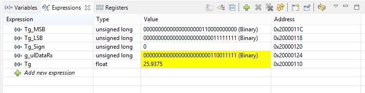
I'm using LM92 as part of a datalogger project, connecting to microprocessor through I2C. I've got the libraary to work after a few shots, but now I'm having an issue. First byte is always a correct value, but the problem comes when I get my second byte, that is always 11111111. Getting rid of those 3 state bytes, so we have 00011111. The result is that when I convert it to a float, I always get xx.9375, hence always an error.
So I tried the sensor using Energia, and there it seems to be working fine.
I'm attaching my code and a debug screenshot. If anyone would see what am I doing wrong, I would really appreciate it!
Thanks!
Franco
________________________________________________________________________________
/*****************************************************************************************************
* Include
****************************************************************************************************/
// utils
#include "utils/uartstdio.h"
// inc
#include "inc/hw_memmap.h"
#include "inc/hw_types.h"
#include "inc/hw_i2c.h"
#include "inc/hw_ints.h"
// driverlib
#include "driverlib/interrupt.h"
#include "driverlib/i2c.h"
#include "driverlib/sysctl.h"
#include "driverlib/gpio.h"
//*****************************************************************************
//
//! \addtogroup i2c_examples_list
//! <h1>Slave Receive Interrupt (slave_receive_int)</h1>
//!
//! This example shows how to configure a receive interrupt on the slave
//! module. This includes setting up the I2C0 module for loopback mode as well
//! as configuring the master and slave modules. Loopback mode internally
//! connects the master and slave data and clock lines together. The address
//! of the slave module is set to a value so it can receive data from the
//! master.
//!
//! This example uses the following peripherals and I/O signals. You must
//! review these and change as needed for your own board:
//! - I2C0 peripheral
//! - GPIO Port B peripheral (for I2C0 pins)
//! - I2C0SCL - PB2
//! - I2C0SDA - PB3
//!
//! The following UART signals are configured only for displaying console
//! messages for this example. These are not required for operation of I2C.
//! - UART0 peripheral
//! - GPIO Port A peripheral (for UART0 pins)
//! - UART0RX - PA0
//! - UART0TX - PA1
//!
//! This example uses the following interrupt handlers. To use this example
//! in your own application you must add these interrupt handlers to your
//! vector table.
//! - INT_I2C0 - I2C0SlaveIntHandler
//!
//
//*****************************************************************************
/*****************************************************************************************************
* Function prototypes
****************************************************************************************************/
void Init(void);
void I2CSend();
/*****************************************************************************************************
* Defines
****************************************************************************************************/
// Loopback slave address
#define SLAVE_ADDRESS 0x3C
// LM92 slave address
#define SLAVE_ADDRESS_LM92 0x48+3
// LM92 read command
#define TG_REG_READ 0x00
//LM92 low power mode command
#define TG_REG_LOWPOW 0x01
/*****************************************************************************************************
* Global variables
****************************************************************************************************/
//static unsigned long g_ulDataRx, MSB,LSB, Sign;
static unsigned long g_ulDataRx, Tg_MSB,Tg_LSB, Tg_Sign;
float Tg=0;
/*****************************************************************************************************
* Init
****************************************************************************************************/
void Init(){
//
// Set the clocking to run directly from the external crystal/oscillator.
// TODO: The SYSCTL_XTAL_ value must be changed to match the value of the
// crystal on your board.
//
SysCtlClockSet(SYSCTL_SYSDIV_2_5| SYSCTL_USE_PLL | SYSCTL_OSC_INT | SYSCTL_XTAL_16MHZ);
//
// The I2C0 peripheral must be enabled before use.
//
SysCtlPeripheralEnable(SYSCTL_PERIPH_I2C0);
//
SysCtlPeripheralReset(SYSCTL_PERIPH_I2C0);
//
// For this example I2C0 is used with PortB[3:2]. The actual port and
// pins used may be different on your part, consult the data sheet for
// more information. GPIO port B needs to be enabled so these pins can
// be used.
// TODO: change this to whichever GPIO port you are using.
//
SysCtlPeripheralEnable(SYSCTL_PERIPH_GPIOB);
//
// Configure the pin muxing for I2C0 functions on port B2 and B3.
// This step is not necessary if your part does not support pin muxing.
// TODO: change this to select the port/pin you are using.
//
GPIOPinConfigure(GPIO_PB2_I2C0SCL);
GPIOPinConfigure(GPIO_PB3_I2C0SDA);
//
// Select the I2C function for these pins. This function will also
// configure the GPIO pins pins for I2C operation, setting them to
// open-drain operation with weak pull-ups. Consult the data sheet
// to see which functions are allocated per pin.
// TODO: change this to select the port/pin you are using.
//
GPIOPinTypeI2C(GPIO_PORTB_BASE, GPIO_PIN_3);
GPIOPinTypeI2CSCL(GPIO_PORTB_BASE, GPIO_PIN_2);
//
// Enable loopback mode. Loopback mode is a built in feature that helps
// for debug the I2Cx module. It internally connects the I2C master and
// slave terminals, which effectively lets you send data as a master and
// receive data as a slave. NOTE: For external I2C operation you will need
// to use external pull-ups that are faster than the internal pull-ups.
// Refer to the datasheet for more information.
//
// TODO: Enable or disable this
// HWREG(I2C0_MASTER_BASE + I2C_O_MCR) |= 0x01;
//
// Enable the I2C0 interrupt on the processor (NVIC).
//
//IntEnable(INT_I2C0);
//
// Configure and turn on the I2C0 slave interrupt. The I2CSlaveIntEnableEx()
// gives you the ability to only enable specific interrupts. For this case
// we are only interrupting when the slave device receives data.
//
//I2CSlaveIntEnableEx(I2C0_SLAVE_BASE, I2C_SLAVE_INT_DATA);
//
// Enable and initialize the I2C0 master module. Use the system clock for
// the I2C0 module. The last parameter sets the I2C data transfer rate.
// If false the data rate is set to 100kbps and if true the data rate will
// be set to 400kbps. For this example we will use a data rate of 100kbps.
//
I2CMasterInitExpClk(I2C0_MASTER_BASE, SysCtlClockGet(), false);
SysCtlDelay(10000);
//
//clear I2C FIFOs
//HWREG(I2C0_MASTER_BASE + I2C_O_FIFOCTL) = 80008000;
//
// Enable the I2C0 slave module.
//
//I2CSlaveEnable(I2C0_SLAVE_BASE);
//
// Set the slave address to SLAVE_ADDRESS. In loopback mode, it's an
// arbitrary 7-bit number (set in a macro above) that is sent to the
// I2CMasterSlaveAddrSet function.
//
// TODO; change address
//I2CSlaveInit(I2C0_SLAVE_BASE, SLAVE_ADDRESS);
//
// Tell the master module what address it will place on the bus when
// communicating with the slave. Set the address to SLAVE_ADDRESS
// (as set in the slave module). The receive parameter is set to false
// which indicates the I2C Master is initiating a writes to the slave. If
// true, that would indicate that the I2C Master is initiating reads from
// the slave.
//
// TODO; change address
I2CMasterSlaveAddrSet(I2C0_MASTER_BASE, SLAVE_ADDRESS_LM92, false);
//
// Enable interrupts to the processor.
//
//IntMasterEnable();
}
/*****************************************************************************************************
* Main
*
* Configure the I2C0 master and slave and connect them using loopback mode.
*
****************************************************************************************************/
int main(void){
unsigned long ulDataTx;
//
// Wait for interrupt to occur.
//
/*while(!g_ulIntFlag)
{
}*/
//
// Loop forever.
//
while(1)
{
//
// Write the address first with direction as transmit to write the address for read
//
I2CMasterSlaveAddrSet(I2C0_MASTER_BASE,SLAVE_ADDRESS_LM92, false);
I2CMasterDataPut(I2C0_MASTER_BASE, TG_REG_READ);
I2CMasterControl(I2C0_MASTER_BASE, I2C_MASTER_CMD_BURST_SEND_START);
while(!I2CMasterBusy(I2C0_MASTER_BASE));
while(I2CMasterBusy(I2C0_MASTER_BASE));
//
// Repeated Start now with direction as recieve can be used to get data
//
I2CMasterSlaveAddrSet(I2C0_MASTER_BASE, SLAVE_ADDRESS_LM92, true);
I2CMasterControl(I2C0_MASTER_BASE, I2C_MASTER_CMD_BURST_RECEIVE_START);
while(!I2CMasterBusy(I2C0_MASTER_BASE));
while(I2CMasterBusy(I2C0_MASTER_BASE));
// Most significant bits
Tg_MSB = I2CMasterErr(I2C0_MASTER_BASE);
Tg_MSB = I2CMasterDataGet(I2C0_MASTER_BASE) << 8;
//Tg_MSB = Tg_MSB << 8;
// Less significant bits
I2CMasterControl (I2C0_MASTER_BASE, I2C_MASTER_CMD_BURST_RECEIVE_FINISH);
while(!I2CMasterBusy(I2C0_MASTER_BASE));
while(I2CMasterBusy(I2C0_MASTER_BASE));
Tg_LSB = I2CMasterDataGet(I2C0_MASTER_BASE);
// Low power mode on
I2CMasterSlaveAddrSet(I2C0_MASTER_BASE,SLAVE_ADDRESS_LM92, false);
I2CMasterDataPut(I2C0_MASTER_BASE, TG_REG_LOWPOW);
I2CMasterControl(I2C0_MASTER_BASE, I2C_MASTER_CMD_BURST_SEND_START);
while(!I2CMasterBusy(I2C0_MASTER_BASE));
while(I2CMasterBusy(I2C0_MASTER_BASE));
// Final value
g_ulDataRx = (Tg_MSB+ Tg_LSB) >> 3;
//g_ulDataRx = g_ulDataRx + Tg_LSB;
//g_ulDataRx = g_ulDataRx >> 3;
Tg_Sign = g_ulDataRx & 0x1000;
Tg = g_ulDataRx*0.0625;
}
}