This thread has been locked.

If you have a related question, please click the "Ask a related question" button in the top right corner. The newly created question will be automatically linked to this question.

TM4C1290NCPDT EMI issue

Other Parts Discussed in Thread: TM4C1290NCPDT, TM4C1230C3PM, TM4C1292NCPDT, EK-TM4C129EXL, TM4C123GH6PM, TM4C129XNCZAD, EK-TM4C1294XL

I have a design, based on the TM4C1290NCPDT.

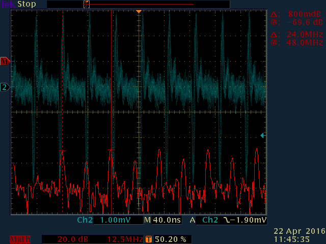
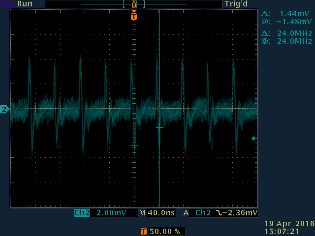
This is giving an issue when EMC testing, with an apparent 24MHz signal giving radiated emissions way above the EU thresholds, this shows particularly at 96MHz and 120MHz, although the strength of these harmonics is likely caused by the cable lengths.

Using a magnetic field probe this was traced to the TM4C, on the board.

When testing other Stellaris and TIVA micro based designs this was not apparent. 
I have checked the DK-TM4C129X Tiva C Series Connected Development Kit, and this does not do this.
I have checked a TM4C1230C3PM based design, and this does not do this.
I have checked a LM3S9B92-IQC80-C5 based design, and this does not do this.

In an attempt to narrow down what may have been causing this I have performed the following 'modifications' without affecting this radiated signal:

1. Erased the flash, and cycled the power.

2. Created a new CCS project where I set the clock to use the internal oscillator, ensure that MOSC is disabled, ensure that DIVSCLK is disabled, disabled AHB for all peripherals, disabled clock gating, disabled every peripheral, powered off every peripheral and disabled the PLL.

int main(void)
{
	/* Do a setup to disable everything. This should show if the 24MHz  */
	/* giving issue with radiated emissions is endemic to this part...  */
	/* Setup the CPU clock, to use int 16MHz                            */
	   SysCtlClockFreqSet((SYSCTL_OSC_INT | SYSCTL_USE_OSC | SYSCTL_CFG_VCO_320), 16000000);
	   SysCtlMOSCConfigSet(SYSCTL_MOSC_NO_XTAL | SYSCTL_MOSC_PWR_DIS);

	/* Disable the DIVSCLK output (should be all defaults)				*/
	   SysCtlClockOutConfig((SYSCTL_CLKOUT_DIS | SYSCTL_CLKOUT_SYSCLK), 1);

	/* Disable ALL peripherals.                                 		*/
	   SysCtlGPIOAHBDisable(SYSCTL_PERIPH_GPIOA);
	   SysCtlGPIOAHBDisable(SYSCTL_PERIPH_GPIOB);
	   SysCtlGPIOAHBDisable(SYSCTL_PERIPH_GPIOC);
	   SysCtlGPIOAHBDisable(SYSCTL_PERIPH_GPIOD);
	   SysCtlGPIOAHBDisable(SYSCTL_PERIPH_GPIOE);
	   SysCtlGPIOAHBDisable(SYSCTL_PERIPH_GPIOF);
	   SysCtlGPIOAHBDisable(SYSCTL_PERIPH_GPIOG);
	   SysCtlGPIOAHBDisable(SYSCTL_PERIPH_GPIOH);
	   SysCtlGPIOAHBDisable(SYSCTL_PERIPH_GPIOJ);

	   SysCtlPeripheralClockGating(false);

	   SysCtlPeripheralDisable(SYSCTL_PERIPH_ADC0);
	   SysCtlPeripheralDisable(SYSCTL_PERIPH_ADC1);
	   SysCtlPeripheralDisable(SYSCTL_PERIPH_CAN0);
	   SysCtlPeripheralDisable(SYSCTL_PERIPH_CAN1);
	   SysCtlPeripheralDisable(SYSCTL_PERIPH_CCM0);
	   SysCtlPeripheralDisable(SYSCTL_PERIPH_COMP0);
	   SysCtlPeripheralDisable(SYSCTL_PERIPH_EEPROM0);
//	   SysCtlPeripheralDisable(SYSCTL_PERIPH_EMAC); // not on TM4C1290
//	   SysCtlPeripheralDisable(SYSCTL_PERIPH_EPHY); // not on TM4C1290
	   SysCtlPeripheralDisable(SYSCTL_PERIPH_EPI0);
	   SysCtlPeripheralDisable(SYSCTL_PERIPH_GPIOA);
	   SysCtlPeripheralDisable(SYSCTL_PERIPH_GPIOB);
	   SysCtlPeripheralDisable(SYSCTL_PERIPH_GPIOD);
	   SysCtlPeripheralDisable(SYSCTL_PERIPH_GPIOE);
	   SysCtlPeripheralDisable(SYSCTL_PERIPH_GPIOF);
	   SysCtlPeripheralDisable(SYSCTL_PERIPH_GPIOG);
	   SysCtlPeripheralDisable(SYSCTL_PERIPH_GPIOH);
	   SysCtlPeripheralDisable(SYSCTL_PERIPH_GPIOJ);
	   SysCtlPeripheralDisable(SYSCTL_PERIPH_GPIOK);
	   SysCtlPeripheralDisable(SYSCTL_PERIPH_GPIOL);
	   SysCtlPeripheralDisable(SYSCTL_PERIPH_GPIOM);
	   SysCtlPeripheralDisable(SYSCTL_PERIPH_GPION);
	   SysCtlPeripheralDisable(SYSCTL_PERIPH_GPIOP);
	   SysCtlPeripheralDisable(SYSCTL_PERIPH_GPIOQ);
	   SysCtlPeripheralDisable(SYSCTL_PERIPH_GPIOR);
	   SysCtlPeripheralDisable(SYSCTL_PERIPH_GPIOS);
	   SysCtlPeripheralDisable(SYSCTL_PERIPH_GPIOT);
	   SysCtlPeripheralDisable(SYSCTL_PERIPH_HIBERNATE);
	   SysCtlPeripheralDisable(SYSCTL_PERIPH_I2C0);
	   SysCtlPeripheralDisable(SYSCTL_PERIPH_I2C1);
	   SysCtlPeripheralDisable(SYSCTL_PERIPH_I2C2);
	   SysCtlPeripheralDisable(SYSCTL_PERIPH_I2C3);
	   SysCtlPeripheralDisable(SYSCTL_PERIPH_I2C4);
	   SysCtlPeripheralDisable(SYSCTL_PERIPH_I2C5);
	   SysCtlPeripheralDisable(SYSCTL_PERIPH_I2C6);
	   SysCtlPeripheralDisable(SYSCTL_PERIPH_I2C7);
	   SysCtlPeripheralDisable(SYSCTL_PERIPH_I2C8);
	   SysCtlPeripheralDisable(SYSCTL_PERIPH_I2C9);
	   SysCtlPeripheralDisable(SYSCTL_PERIPH_LCD0);
	   SysCtlPeripheralDisable(SYSCTL_PERIPH_ONEWIRE0);
	   SysCtlPeripheralDisable(SYSCTL_PERIPH_PWM0);
	   SysCtlPeripheralDisable(SYSCTL_PERIPH_PWM1);
	   SysCtlPeripheralDisable(SYSCTL_PERIPH_QEI0);
	   SysCtlPeripheralDisable(SYSCTL_PERIPH_QEI1);
	   SysCtlPeripheralDisable(SYSCTL_PERIPH_SSI0);
	   SysCtlPeripheralDisable(SYSCTL_PERIPH_SSI1);
	   SysCtlPeripheralDisable(SYSCTL_PERIPH_SSI2);
	   SysCtlPeripheralDisable(SYSCTL_PERIPH_SSI3);
	   SysCtlPeripheralDisable(SYSCTL_PERIPH_TIMER0);
	   SysCtlPeripheralDisable(SYSCTL_PERIPH_TIMER1);
	   SysCtlPeripheralDisable(SYSCTL_PERIPH_TIMER2);
	   SysCtlPeripheralDisable(SYSCTL_PERIPH_TIMER3);
	   SysCtlPeripheralDisable(SYSCTL_PERIPH_TIMER4);
	   SysCtlPeripheralDisable(SYSCTL_PERIPH_TIMER5);
	   SysCtlPeripheralDisable(SYSCTL_PERIPH_TIMER6);
	   SysCtlPeripheralDisable(SYSCTL_PERIPH_TIMER7);
	   SysCtlPeripheralDisable(SYSCTL_PERIPH_UART0);
	   SysCtlPeripheralDisable(SYSCTL_PERIPH_UART1);
	   SysCtlPeripheralDisable(SYSCTL_PERIPH_UART2);
	   SysCtlPeripheralDisable(SYSCTL_PERIPH_UART3);
	   SysCtlPeripheralDisable(SYSCTL_PERIPH_UART4);
	   SysCtlPeripheralDisable(SYSCTL_PERIPH_UART5);
	   SysCtlPeripheralDisable(SYSCTL_PERIPH_UART6);
	   SysCtlPeripheralDisable(SYSCTL_PERIPH_UART7);
	   SysCtlPeripheralDisable(SYSCTL_PERIPH_UDMA);
	   SysCtlPeripheralDisable(SYSCTL_PERIPH_USB0);
	   SysCtlPeripheralDisable(SYSCTL_PERIPH_WDOG0);
	   SysCtlPeripheralDisable(SYSCTL_PERIPH_WDOG1);
	   SysCtlPeripheralDisable(SYSCTL_PERIPH_WTIMER0);
	   SysCtlPeripheralDisable(SYSCTL_PERIPH_WTIMER1);
	   SysCtlPeripheralDisable(SYSCTL_PERIPH_WTIMER2);
	   SysCtlPeripheralDisable(SYSCTL_PERIPH_WTIMER3);
	   SysCtlPeripheralDisable(SYSCTL_PERIPH_WTIMER4);
	   SysCtlPeripheralDisable(SYSCTL_PERIPH_WTIMER5);

	   SysCtlPeripheralPowerOff(SYSCTL_PERIPH_CAN0);
	   SysCtlPeripheralPowerOff(SYSCTL_PERIPH_CAN1);
//	   SysCtlPeripheralPowerOff(SYSCTL_PERIPH_EMAC); // not on TM4C1290
//	   SysCtlPeripheralPowerOff(SYSCTL_PERIPH_EPHY); // not on TM4C1290
	   SysCtlPeripheralPowerOff(SYSCTL_PERIPH_LCD0);
	   SysCtlPeripheralPowerOff(SYSCTL_PERIPH_USB0);

	   SysCtlUSBPLLDisable();

	/* Now do an infinite loop 											*/
	while (1) {}
}

3. Physically cut the pins to all pins for PortA, B, C, D, E, F, G, H, J, K, L, M, N, P and Q. Essentially all of the I/O pins. This is listed as acceptable for unused I/O.

4. Disconnected the hibernation pins, VBAT, HIB, WAKE, XOSC0 and XOSC1. This is listed as acceptable for these pins when unused.

5. disconnected the MOSC pins OSC0 and OSC1. This is listed as acceptable for these pins when unused.

So I now have the TM4C1290NCPDT connected to just the power pins, including VREFA+ and VDDA, with a 100k pull-up on RST, and this still has the unintended 24MHz radiated emissions.

If I hold the TM4C1290NCPDT in reset, by connecting ONLY the RST input to Ground, then the 24MHz radiated emissions stops, verifying that the TM4C is the source.

Is this a known issue for this particular part? I have not found anything to this end in the errata document SPMZ850D.
Is this an issue with just the TM4C1290?
Is this an issue with TM4C in the PDT package?

Thanks in advance for any help,

Kevin.


  • Hello Kevin,

    The DK-TM4C129X has the same device family class as the TM4C1290NCPDT. So it may be something to do with the PCB layout and the device.

    Is there a good continuous GND and Power plane underneath the device.

    Regards
    Amit
  • Amit,

    The stack-up uses the four-layer stack-up as shown in section 3.2.1 of the 'System Design Guidelines', SPMA056, including having the ground plane closest to the component side.

    Regards,
    Kevin.
  • Hello Kevin,

    If the flash is erased, then does the issue appear as well? What I am trying to ascertain is what is the source of the 24MHz, since the crystal is not being used and there is nothing in the device which should be having a 24MHz as a clock or derived clock.

    Regards
    Amit
  • Amit,

    Yes this is still apparent with the flash erased.

    So far all I can attribute the issue to is the TM4C1290NCPDT.
    Others that we have checked are OK, like the DK-TM4C129X.
    So I wondered whether it was some anomaly with the 1290, the PDT package or the combination.

    We have also checked to ensure that we do not have 48MHz noise on VDDC, VDD and VDDA.

    Regards,
    Kevin.
  • Kevin Kilford said:
    We have also checked to ensure that we do not have 48MHz noise on VDDC, VDD and VDDA.

    Hello Kevin

    You mean 24MHz noise on the VDDC, VDD and VDDA.

    I think I know where the 48MHz is coming from, but it cannot be disabled on the TM4C129 devices. Which leads to me believe, that the issue is because of the PDT package. There is one experiment that we can perform to see if the theory is true. This requires that the device be put in Deep Sleep Mode with clock from the LFIOSC. Let me see if I can share a binary file to do the same.

    Regards,

    Amit

  • Amit,

    I had meant 24Mhz, as shown in the oscilloscope trace, sorry.

    I will certainly try a binary if you have one available.

    Regards,
    Kevin
  • Hello Kevin,

    I spoke with one of my co-workers, and he is concerned about the measurement performed on the power pins and suspects that a scope is not correct equipment and the type of probe circuit for measurement. He has suggested

    1. Use a spectrometer to visualize the signal instead of a scope?
    2. We would also like to review the measurement technique on the Power IO's. Is there some kind of high pass filter being used with terminated load?

    In the meantime I am working on the deep sleep test, while we await more details from you.

    Regards
    Amit
  • Amit,

    Unfortunately I don't have a spectrum analyser to look at the power pins, for your suggestion 1.

    I am not sure that I understand suggestion 2.
    Is this related to how we are measuring the 24MHz signal?
    This is using a passive magnetic field probe with a 500MHz, 5GS/s oscilloscope.
    When the probe is aligned in a particular way above the TM4C we pick up the trace as shown in my original question. When the TM4C is held in reset the 24MHz signal in the trace will disappear.

    Regards,
    Kevin.
  • Hello Kevin,

    In an earlier post you had mentioned "We have also checked to ensure that we do not have 48MHz noise on VDDC, VDD and VDDA."

    The VDD and GND pins are not adjacent for all placements on the PDT package. So the suspicion is that a large current loop is being created. Hence we need to revisit the measurements on the power rails to see if that is causing a sort of amplification. To be able to do that we would need to measure the power rail signals using a spectrum analyzer with a high pass filter such that the cutoff is in KHz. Hence the measurement circuit for the power rails.

    Regards
    Amit
  • Hello Kevin,

    Is there any GPIO that is available that can be connected to VDD (via a pull up) or GND via a switch if possible, so that I can build a safety mechanism to halt the CPU before deep sleep

    Regards
    Amit
  • Amit,

    PQ0, on Pin 5 can be used for this.

    Thank you,

    Kevin.

  • Amit,

    We have looked at all of the power pins (VDD, VDDC and VDDA) and we don't detect any 24MHz noise on any, using a spectrum analyser.

    Regards,
    Kevin
  • Hello Kevin,

    Is it OK, that if the pin is held Active High then the code will not execute? Or do you want it to be of the opposite polarity

    Regards
    Amit
  • Amit,

    Can we have it so that the code does not execute if PQ0 is tied low?

    Thanks,
    Kevin.
  • Hello Kevin,

    Attached is the binary file that you would need to flash to the device. Please note that I have renamed the file extension as nib (to avoid net filter issues)

    https://e2e.ti.com/cfs-file/__key/communityserver-discussions-components-files/908/tm4c1290_5F00_sleeptest.nib

    Also attached is the source file.

    /*
     * main.c
     */
    #include "stdint.h"
    #include "stdbool.h"
    #include "inc/hw_gpio.h"
    #include "inc/hw_memmap.h"
    #include "inc/hw_sysctl.h"
    #include "inc/hw_types.h"
    #include "driverlib/gpio.h"
    #include "driverlib/sysctl.h"
    
    int main(void)
    {
    	//
    	// Set System clock to 16MHz Internal Oscillator
    	//
    	//SysCtlClockFreqSet(( SYSCTL_OSC_INT | SYSCTL_USE_OSC | SYSCTL_CFG_VCO_480),
    	//		16000000);
    	
    	//SysCtlMOSCConfigSet(SYSCTL_MOSC_PWR_DIS);
    
    	SysCtlPeripheralDisable(SYSCTL_PERIPH_GPIOQ);
    	SysCtlPeripheralReset(SYSCTL_PERIPH_GPIOQ);
    	SysCtlPeripheralEnable(SYSCTL_PERIPH_GPIOQ);
    
    	while(!(SysCtlPeripheralReady(SYSCTL_PERIPH_GPIOQ)));
    	GPIOPinTypeGPIOInput(GPIO_PORTQ_BASE, GPIO_PIN_0);
    
    	while(GPIOPinRead(GPIO_PORTQ_BASE, GPIO_PIN_0) == 0x0);
    
    	//
    	// Configure Sleep Mode
    	//
    	SysCtlDeepSleepPowerSet(SYSCTL_FLASH_LOW_POWER | SYSCTL_SRAM_NORMAL);
    	SysCtlDeepSleepClockConfigSet(1, SYSCTL_DSLP_OSC_INT30 | SYSCTL_DSLP_PIOSC_PD);
    
    	SysCtlPeripheralClockGating(true);
    
    	SysCtlDeepSleep();
    
    	while(1);
    
    	return 0;
    }
    

    Regards

    Amit

  • I've not been able to determine if this issue is a, "Single Board Anomaly!" Does this effect reveal across different boards? (from the same build batch or otherwise)

    Amit's noted the potential presence of 48MHz. That appears to be the 3rd harmonic of the internal oscillator - the 24MHz is difficult to explain...
  • Hello cb1

    Following your first rule here: KISS. Let us first isolate the high frequency clock sources as the design is complicated that a 48MHz may be divided to 24MHz internally for an internal operation.

    And yes, it makes sense to take a larger spectrum of devices.

    Regards
    Amit
  • cb1,

    This occurs over the entire prototype build of our product.

    Regards,
    Kevin
  • Amit,

    Once programmed with your binary and PQ0 pulled high, as indicated in the source code, the 24MHz radiation is no longer detected, when the processor is in deep sleep mode.
    If I then pull PQ0 low, and power cycle the board, I can detect the 24MHz radiation again.

    Does this point to the source that can only be disabled by entering deep sleep mode?

    Thank you,
    Kevin.
  • Hello Kevin

    What is the Crystal connected on your board? Also this experiment gives us a direction to isolate the source of the emissions, as one of the on-chip high frequency clocks. Now I need to see how I can isolate the 16MHz and the 48MHz sources,

    Regards
    Amit
  • Amit,

    The design has a 16MHz NX3225GA-16.000M-STD-CRG-2 crystal for MOSC, as shown in table 26-24 of the datasheet.
    The design also includes a 32.768kHz crystal for the hibernation module.

    The board that we have been experimenting on has both of these removed and so only has the PIOSC available.
    We do see the radiated signal with either the MOSC or the PIOSC.

    The original crystals can be reinstated if required.

    Regards,
    Kevin.
  • Hello Kevin

    Thank you for the confirmation on the crystal frequency and the fact that MOSC is disconnected.

    However the second statement on not seeing radiated signal with PIOSC is not correct, I would say. The reason is because the PIOSC is always active if the MOSC pin OSC0 is connected to GND. So PIOSC will be active (unless the code provided earlier is used which shuts down both the PIOSC and the 48MHz clock). I am trying to see if there is a method by which the 48MHz clock can be shut down to isolate it to the specific clock.

    Regards
    Amit
  • Amit,

    What I was trying to say was that we do see the emissions when using the MOSC and we also see the emissions with the MOSC removed and the micro set to use the PIOSC.

    Regards,
    Kevin.
  • Hello Kevin,

    Looking at the design, I don't think we can shut down the 48MHz clock as long as the PIOSC is active. Only deep sleep provides the capability, but then that is not a data processing state.

    Regards
    Amit
  • Purely anecdotal yet ("any" port in a storm). I recall a client of ours failing FCC EMI qualification (only) when the PLL was enabled. By "trial & error" (and repeated measurements) we noted that "certain" xtals & xtal frequencies - and their impact upon PLL settings - produced a fairly substantial range in EMI levels. There proved to be even different EMI levels based upon xtal vendor.

    Now your case appears to impact when NO xtal is present - my report (above) is to add input which may benefit poster's (real) application - where he noted TWO xtals are, "in play."

    As I recall - the VDDA line was improperly filtered and/or insufficient number/quality of bypass caps were used on our client's board.

    And - this EMI is sometimes noted when the MCU is inadequately powered - a (temporary) change of 3V3 regulator and/or adding more filtering (to both input & output side) of the existing regulator "has" lowered such emissions.

    Our firm works w/ARM MCUs from multiple vendors - our client's MCU was NOT this vendors!   My hope is that (some - even one) of these findings may assist or serve as an investigatory trigger...

  • Amit,

    I presume that your experiment has shown that we are detecting this clock, that is part of the PIOSC, as the radiation only stops when we enter deep sleep.

    Is the PIOSC powered through a particular power pin, so that we could ensure that the power there cannot be causing an issue?

    Does anyone at TI have any experience of what can cause this 48MHz clock to behave in a way that could cause what we are experiencing?

    I have ordered a TM4C1292NCPDT with a view to fitting this onto our design and see if we still get the issue.
    We can set this to have the same pin-out etc. as the only difference is the internal MAC, and we should be able to disable that.
    I have also ordered a EK-TM4C129EXL, to see if another TIVA processor in the PDT package, but on a different design board, shows the same symptoms. This part has the MAC+PHY, but is the closest I have found.

    Regards,
    Kevin
  • Hello Kevin,

    Attached is another bin file with sleep mode enabled. This is to further root cause the issue cone.

    https://e2e.ti.com/cfs-file/__key/communityserver-discussions-components-files/908/2450.tm4c1290_5F00_sleeptest.nib

    And the corresponding code

    /*
     * main.c
     */
    #include "stdint.h"
    #include "stdbool.h"
    #include "inc/hw_gpio.h"
    #include "inc/hw_memmap.h"
    #include "inc/hw_sysctl.h"
    #include "inc/hw_types.h"
    #include "driverlib/gpio.h"
    #include "driverlib/sysctl.h"
    
    int main(void)
    {
    	//
    	// Set System clock to 16MHz Internal Oscillator
    	//
    	//SysCtlClockFreqSet(( SYSCTL_OSC_INT | SYSCTL_USE_OSC | SYSCTL_CFG_VCO_480),
    	//		16000000);
    	
    	//SysCtlMOSCConfigSet(SYSCTL_MOSC_PWR_DIS);
    
    	SysCtlPeripheralDisable(SYSCTL_PERIPH_GPIOQ);
    	SysCtlPeripheralReset(SYSCTL_PERIPH_GPIOQ);
    	SysCtlPeripheralEnable(SYSCTL_PERIPH_GPIOQ);
    
    	while(!(SysCtlPeripheralReady(SYSCTL_PERIPH_GPIOQ)));
    	GPIOPinTypeGPIOInput(GPIO_PORTQ_BASE, GPIO_PIN_0);
    
    	while(GPIOPinRead(GPIO_PORTQ_BASE, GPIO_PIN_0) == 0x0);
    
    	//
    	// Configure Sleep Mode
    	//
    	SysCtlSleepPowerSet(SYSCTL_FLASH_LOW_POWER | SYSCTL_SRAM_NORMAL);
    	//SysCtlDeepSleepClockConfigSet(1, SYSCTL_DSLP_OSC_INT30 | SYSCTL_DSLP_PIOSC_PD);
    
    	SysCtlPeripheralClockGating(true);
    
    	SysCtlSleep();
    
    	while(1);
    
    	return 0;
    }
    

    As for your questions

    1. No PIOSC or 48MHz are not powered by a particular power pin

    2. So far the EU EMI requirements were not this tight and hence customers may not have reported the emissions.

    3. Since, we have not seen it either till now, it would be a full debug as well for us to understand the root cause

    4. A connected launchpad would be a good candidate. However do note that there is a TM4C123GH6PM as well on the board which may be a cause of emission as well.

    5. It would be good if you can share the layout of the board.

    Regards

    Amit

  • cb1,

    Thanks, all input gladly received.

    I had noticed, previously, although not recorded here, that all of the other designs that I have checked, and found that they did not do this, have 25MHz main oscillator (MOSC) frequency.
    This would be due to the requirement for Ethernet or USB, that I am not using.

    I had discounted this when we had the same symptoms when running from the internal oscillator (PIOSC), but could revisit this to see if a 25MHz crystal has an effect.

    Both the bulk and decoupling caps on VDDA match that specified in the System Design Guidelines SPMA056.

    The 3.3V regulator is a 1A linear regulator.
    The output is very stable with no more than 50mA being drawn.
    Adding capacitance to the input and output has not had any effect on the radiated emissions.

    Regards,
    Kevin
  • Amit,

    The 48MHz radiation is NOT apparent when we enter sleep mode either.
    It only shows with this new binary when PQ0 is held low.
    So, I guess it is a clock that is disabled during sleep mode and deep sleep mode.

    In response to your answers:
    2. The levels we are experiencing would also fail FCC. However, it is never a straight comparison as it will depend upon the type, length and number of cables to the device, which acts as a antenna for the 'noise'.

    4. I am aware of the other micro in the ICDI. As I am currently using a small near-field probe I am able to distinguish that the emission is coming from a particular device.

    5. As this is a design for a client I am not in a position to publicly release the entire PCB design.
    Would the part of the PCB restricted to the micro be enough, as I may be able to get authorization for that?

    Regards,
    Kevin.
  • Hello Kevin,

    That is very interesting, since I have not shut down the clock source in 2nd code. Both PIOSC and 48MHz clock source are active in this case, which narrows the issue down to the Flash controller, and that is same between the TM4C129XNCZAD and TM4C1290NCPDT.

    I have asked my team to check if test boards like the EK-TM4C1294XL or 128 QFP parts have been submitted by customers for FCC approvals.

    It would be OK, for the micro part of the layout to be released.

    Regards
    Amit
  • Amit,

    Interestingly I have been able to detect the same emission on the DK-TM4C129X, albeit at a very low level (1/10th of the signal from my board) and it is really only discernible when the flash is erased, so that it is running from the PIOSC.

    Regards,
    Kevin.
  • Hello Kevin,

    May be the BGA package where VDD and GND are adjacent pins help reduce the current drawn effect on the emission loop. I think only with the Launchpad which has the 128 QFP package, can we know if it is package related.

    Regards
    Amit
  • Amit,

    I think that you are correct: The BGA package has a smaller loop for the power and return, so does not exhibit the issue to the same degree.

    I have now tested an EK-TM4C1294XL.
    This was powered from the USB debug port and have the result shown below:

    The blue trace is captured using a passive near-field H probe with a diameter of 3cm.
    The red trace is an FFT conversion of the blue trace. The markers are at 24MHz and 48MHz.

    This is almost exactly what we are seeing with my board, so it would seem that the common QFP package is the most likely cause.

    The possible reason that this is not causing issues for other people would be that some of the tracks that run underneath the micro on my board are picking this emission up and transferring it to one of the many cables that we have.
    The cable then acts as a transmitter, and may even be a good length to resonate making things worse still.

    It looks like we will need to recut our board to either use the BGA package or reduce the amount of this signal that can get onto our cables.

    Regards,

    Kevin

  • Hello Kevin,

    Thanks for tracking it down. And we do know the source of the signal as well.

    Regards
    Amit
  • Amit,

    Was it the flash controller?

    Regards,
    Kevin
  • Hello Kevin,

    Yes, it is the flash controller which gets the 48MHz clock

    Regards
    Amit