This thread has been locked.

If you have a related question, please click the "Ask a related question" button in the top right corner. The newly created question will be automatically linked to this question.

BMP180 Sensor I2CMDR not working

Other Parts Discussed in Thread: TM4C123GH6PM

Hi,

I am trying to interface BMP180 module to my TM4C123GXL microcontroller kit. Here is my code:

#include <stdint.h>
#include <stdbool.h>
#include <string.h>
#include "tm4c123gh6pm.h"
#include "wait.h"

// Addresses as per the Bosch datasheet

#define BMP180_ADDR_W 0xEE  
#define BMP180_ADDR_R 0xEF

// I2C Master Control/Status Register (Read Only)

#define I2C1_MCS_BUSY 0x01
#define I2C1_MCS_ERR 0x02

// I2C Master Control/Status Register (Write Only)
#define I2C1_MCS_ACK 0x08
#define I2C1_MCS_NACK 0x00
#define I2C1_MCS_STOP 0x04
#define I2C1_MCS_START 0x02
#define I2C1_MCS_RUN 0x01

void initHw()
{
// Configure HW to work with 16 MHz XTAL, PLL enabled, system clock of 40 MHz
SYSCTL_RCC_R = SYSCTL_RCC_XTAL_16MHZ | SYSCTL_RCC_OSCSRC_MAIN | SYSCTL_RCC_USESYSDIV | (4 << SYSCTL_RCC_SYSDIV_S);

// Set GPIO ports to use APB (not needed since default configuration -- for clarity)
// Note UART on port A must use APB
SYSCTL_GPIOHBCTL_R = 0;

// Enable GPIO port B and E peripherals
SYSCTL_RCGC2_R |= SYSCTL_RCGC2_GPIOA;

// Configure the I2C module 1 for BMP180 sensor
SYSCTL_RCGCI2C_R |= SYSCTL_RCGCI2C_R1;
waitMicrosecond(1000);
GPIO_PORTA_AFSEL_R |= 0xC0;
GPIO_PORTA_DEN_R |= 0xC0;
GPIO_PORTA_ODR_R |= 0x80;
GPIO_PORTA_PUR_R |= 0x40;
GPIO_PORTA_PCTL_R |= ((3<<28)|(3<<24));
I2C1_MCR_R |= 0x10;
I2C1_MTPR_R = (19<<0);
}

void slaveAddress(uint16_t address)
{
I2C1_MSA_R = (address);
}

int main(void)
{
initHw();
slaveAddress(BMP180_ADDR_W);
I2C1_MDR_R = 0xEE;
I2C1_MCS_R |= (I2C1_MCS_START|I2C1_MCS_RUN|I2C1_MCS_STOP);
while(1);
}

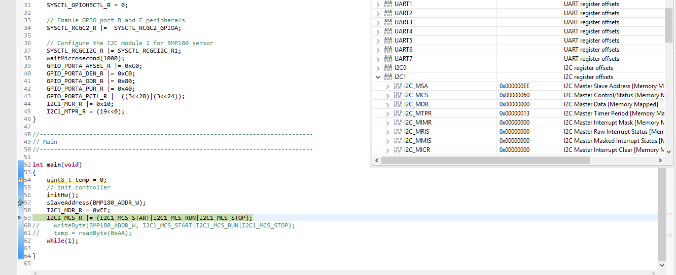
i didn't use any external pull-up resistors. Activated the internal pull ups as shown in the code.

On debugging, the I2CMSA register gets updated with the value of the slave address of BMP180 i.e. 0xEE but, the I2CMDR register value doesn't change. Why is this happening??

Regards,

Rohan

  • Hello Rohan,

    Generally speaking, it is recommended that you use external pullups on the SCL and SDA lines since I2C relies on the pins to be in open drain mode and only drives low allowing the pulls to be the driving force between low to high transitions. The on chip pulls may not be sufficiently strong enough to pull the signals high quickly enough to meet rise and fall timing requirements of the protocol. This depends mainly on the speed of the I2C.

    I am assuming that the point of your post is that data is not being received even though you have written 0xEE as the address. Have you verified that the address is being sent and received by the external device? What data rate are you using? Have you been able to view the communications on a scope to make sure your signals/edges are clean?
  • Hi Chuck,

    Well according to the BMP180 Datasheet, the pull up resistor required is 4.7 KOhms for each. I don't know what is the value of the on chip resistor on the Evaluation Kit.

    My main motive was to send a read command to the sensor by the command

    writeByte(BMP180_ADDR_W, I2C1_MCS_START|I2C1_MCS_RUN|I2C1_MCS_STOP);

    I wrote the following function to write a byte to BMP180.

    void writeByte(uint8_t dataByte, uint8_t condition)
    {
    I2C1_MDR_R = dataByte;
    I2C1_MCS_R |= condition;
    while(I2C1_MCS_R & I2C1_MCS_BUSY != 0);
    if(I2C1_MCS_R & I2C1_MCS_ERR != 0)
    {
    I2C1_MCS_R |= I2C1_MCS_STOP;
    while(I2C1_MCS_R & I2C1_MCS_BUSY != 0);
    }
    }
    But, It wasn't working so to debug the problem, I checked it step-by-step and saw that the I2CMSA register is getting updated but, the I2CMDR register is not getting the value of 0xEE.

    The data rate is 100 kHz.
    No, I didn't check my result on a scope.

    From the above information, what do you most likely think is the problem? The external pull up resistors or the code?
  • Rohan,

    First, is there a reason you are not using the TivaWare drivers instead of direct register accesses? This makes lief more difficult for you since there are certain steps that are taken care of in the drivers that may be easily missed using direct register accesses. Also, reading the macro names gives explicit info regarding the the intended register writes, but without the macro definitions, I can'e explicitly state if the write is going to happen as you expect or not.

    With that stated, where do you check the I2CMDR register to see if data is written into it? I still believe it is also worth while to check the signals on the output given the situation with the pulls. If its a short distance, it may still work in standard mode so you may be ok on a limited use basis but it is always a good idea to use the external pulls on I2C.

    Can you zip your project and post it here so that I can try and debug it and get back with you with my findings?
  • I was trying to implement all the functions, starting from I2C intialization from scratch. There is no other reason for not using the TiveWare Driver. But, I will use it if this problem still persists.

    As for your second question, I debugged my program in CCS Compiler, went step-by-step and checked the value in with the "Register" tool.

     As you can see, I debugged through the I2C1MDR register, and the value didn't change as seen in the register tool from the right.

    Here is the project zip file as requested.https://e2e.ti.com/cfs-file/__key/communityserver-discussions-components-files/908/BMP180.7z

  • Here is code that works. I'm using the TM4C1294 Launch Pad but the code should work on yours. I'm also using TI-RTOS but virtually all the code is non-RTOS so you should be good to go. Let me know if you have any problems...

    float altitude;
    char altitudeTempString[50];
    char dateTime[50];
    short AC1, AC2, AC3, B1, B2, MB, MC, MD; //calibration vars
    unsigned short AC4, AC5, AC6; //same
    long UT, UP; //uncompensated temperature and pressure
    float B3, B4, B6, B7, X1t, X1p, X2t, X2p, X3p, B5t, B5p, BMP180_temperature, BMP180_pressure, Altitude;
    int32_t TimestampStart;
    int32_t TimestampStop;
    Types_FreqHz TimestampFreq;
    Types_FreqHz CPUFreq;
    //end of BMP180 vars
    I2C_Handle i2c;
    I2C_Params i2cParams;
    I2C_Transaction i2cTransaction;
    SDSPI_Handle sdspiHandle;
    SDSPI_Params sdspiParams;
    FILE *src;
    uint32_t ui32Period;
    #define BMP180_I2C_ADDRESS 0x77
    tI2CMInstance g_sI2CInst;
    volatile uint_fast8_t g_vui8DataFlag;
    int timerCount = 0;
    time_t secondsTime;
    int test = 0;


    //the BMP180 has 11 calibration constants stored in EEPROM. These constants are unique to each BMP180 module
    void getPressureCalibration(void){
    txBuffer[0] = 0xAA;
    i2cTransaction.slaveAddress = Board_BMP180_ADDR;
    i2cTransaction.writeBuf = txBuffer;
    i2cTransaction.writeCount = 1;
    i2cTransaction.readBuf = rxBufferLong;
    i2cTransaction.readCount = 22;
    I2C_transfer(i2c, &i2cTransaction);
    AC1 = rxBufferLong[0]<<8 | rxBufferLong[1];
    AC2 = rxBufferLong[2]<<8 | rxBufferLong[3];
    AC3 = rxBufferLong[4]<<8 | rxBufferLong[5];
    AC4 = rxBufferLong[6]<<8 | rxBufferLong[7];
    AC5 = rxBufferLong[8]<<8 | rxBufferLong[9];
    AC6 = rxBufferLong[10]<<8 | rxBufferLong[11];
    B1 = rxBufferLong[12]<<8 | rxBufferLong[13];
    B2 = rxBufferLong[14]<<8 | rxBufferLong[15];
    MB = rxBufferLong[16]<<8 | rxBufferLong[17];
    MC = rxBufferLong[18]<<8 | rxBufferLong[19];
    MD = rxBufferLong[20]<<8 | rxBufferLong[21];
    }

    //this task includes reading both the BMP180 temperature and pressure modules
    void taskReadPressure(void){
    while(1)
    {
    Semaphore_pend(ReadPressureSem, BIOS_WAIT_FOREVER); // wait for Sem from timer ISR
    if (!haveCalDataFlag) {
    getPressureCalibration(); //only do it once
    haveCalDataFlag = true;
    }
    // get uncompensated temperature
    txBufferWithData[0] = 0xF4;
    txBufferWithData[1] = 0x2E;
    i2cTransaction.writeCount = 2;
    i2cTransaction.slaveAddress = Board_BMP180_ADDR;
    i2cTransaction.writeBuf = txBufferWithData;
    i2cTransaction.readBuf = rxBuffer;
    i2cTransaction.readCount = 0;
    TransactionOK = I2C_transfer(i2c, &i2cTransaction);
    if (!TransactionOK) {
    System_printf("Transfer failed!\n");
    }
    Task_sleep(5); //wait 5 mSec for reading to complete
    i2cTransaction.writeBuf = txBuffer;
    txBuffer[0] = 0xF6;
    i2cTransaction.writeCount = 1;
    i2cTransaction.readBuf = rxBuffer;
    i2cTransaction.readCount = 2;
    I2C_transfer(i2c, &i2cTransaction);
    UT = rxBuffer[0]<<8 | rxBuffer[1]; //UT = raw temperature data
    //compute temperature
    X1t = ((UT - AC6) * AC5) >> 15;
    X2t = (MC << 11) / (X1t + MD);
    B5t = X1t + X2t;
    BMP180_temperature = ((B5t + 8) / 16) / 10;
    // get uncompensated pressure
    txBufferWithData[0] = 0xF4;
    txBufferWithData[1] = 0x34;
    i2cTransaction.writeCount = 2;
    i2cTransaction.slaveAddress = Board_BMP180_ADDR;
    i2cTransaction.writeBuf = txBufferWithData;
    i2cTransaction.readBuf = rxBuffer;
    i2cTransaction.readCount = 0;
    TransactionOK = I2C_transfer(i2c, &i2cTransaction);
    if (!TransactionOK) {
    System_printf("Transfer failed!\n");
    }
    Task_sleep(5); //wait 5 mSec for reading to complete
    i2cTransaction.writeBuf = txBuffer;
    txBuffer[0] = 0xF6;
    i2cTransaction.writeCount = 1;
    i2cTransaction.readBuf = rxBuffer;
    i2cTransaction.readCount = 2;
    I2C_transfer(i2c, &i2cTransaction);
    UP = rxBuffer[0]<<8 | rxBuffer[1];
    //compute pressure
    B6 = B5t - 4000;
    X1p = (B2 * (B6 * B6 / 4096)) / 2048;
    X2p = AC2 * B6 / 2048;
    X3p = X1p = X2p;
    B3 = ((((long)AC1 * 4 + X3p)) + 2) / 4;
    X1p = AC3 * B6 / 8192;
    X2p = (B1 * (B6 * B6 / 4096)) / 65536;
    X3p = ((X1p + X2p) + 2) / 4;
    B4 = AC4 * (unsigned long)(X3p + 32768) / 32768;
    B7 = ((unsigned long)UP - B3) * (50000);
    if (B7 < 0x80000000) {
    BMP180_pressure = (B7 * 2) / B4;
    }
    else {
    BMP180_pressure = (B7 / B4) * 2;
    }
    X1p = (BMP180_pressure / 256) * (BMP180_pressure / 256);
    X1p = (X1p * 3038) / 65536;
    X2p = (-7357 * BMP180_pressure) / 65536;
    BMP180_pressure = BMP180_pressure + (X1p + X2p + 3791) / 16;
    //compute altitude; uses default sea level pressure; altitude will vary depending on
    //difference between default sea level pressure (29.921 inches of mercury or 101325 Pascal)
    //and the actual pressure
    Altitude = 44330.0f * (1.0f - powf(BMP180_pressure / 101325.0f, 1 / 5.255f));
    Seconds_set(secondsSet);
    secondsTime = time(NULL);
    System_printf("%s", ctime(&secondsTime));
    // System_printf("PressureTemp: %d (C)\n", (int)BMP180_temperature);
    // System_printf("Altitude: %d (Meters)\n", (int)Altitude);
    sprintf(dateTime,"%s",ctime(&secondsTime));
    int length = strlen(dateTime);
    dateTime[length - 1] = 0;
    // sprintf(altitudeTempString,"%s,%f,%f,\n", ctime(&secondsTime),Altitude,BMP180_temperature);
    sprintf(altitudeTempString,"%s,%f,%f,\n", dateTime,Altitude,BMP180_temperature);
    System_flush();
    }
  • Hi Can you attach a zip folder of your project? Your code doesn't show the header files and the in built functions required to interface the sensor.

    Thanks,
    Rohan
  • I wish I could do that for you Rohan, but parts of my program are proprietary and not shareable. I can provide you with a little more detail on the program however. As I mentioned I am using TI-RTOS with a TM4C1294 LaunchPad. Also using CCS version 6. The BMP180 is part of the SensorHub Booster Pack. The SensorHub is mounted on the Booster Pack 1 position of the Launch Pad. I2C7 is used, tied to GPIO PD0 (SCL) and PD1 (SDA). The peripheral enable is--no surprise--I2C7. This is done in the EK_TM4C1294XL.c file. As I looked at my code a little more, I realized that much of it is part of RTOS, for example the i2cTransactions.

    One thing I noticed immediately, comparing the BMP180 data with the example code, is that the SensorHub BMP180 board address is 0x77 and that is different than the address shown in the BMP180 data sheets.

    My sequencing was as follows:

    First get the 11 calibration numbers. I did that with an I2C transaction that brought in 22 bytes, left shifting the first byte 8 places and OR' ing with the second byte. Those 11 data sets are located at BMP180 address 0xAA.

    Second get the temperature data. The BMP180 control byte is at address 0xF4 and 0x2E says get temperature. These two bytes are sent without getting back data. it's important then to wait at least 5 mSec for the BMP180 to process the data request. Then send 0xF6 to get two bytes of data and do the left shift operation again.. This is followed by computing the temperature using the calibration vars.

    Next get the pressure data by sending 0xF4 and 0x34 (0x34 says get pressure), again not getting anything back, waiting another 5 mSec, and sending 0xF6 to get two bytes of data and doing the left shift operation, followed by another calculation to get the pressure. I thought for too long a time that I was doing something wrong because the pressure reading was a negative number, then finally realized that the pressure reading is referenced to the default pressure of 101325 Pa. I'm located in the San Francisco Bay area so the local pressure can easily indicate a higher pressure (lower altitude) than the reference pressure, depending on the current barometer reading.

    Much of what I have been saying you probably already know but I hope that it helps a little :).

    Michael

  • Rohan,

    There is also an example of an interface with the BMP180 included with TivaWare. When TivaWare is installed to its default directory path, the example will be located at C:\ti\TivaWare_C_Series-2.1.1.71\examples\boards\ek-tm4c123gxl-boostxl-senshub\pressure_bmp180\

    This example uses I2C3 for communication with the BMP180 and is, perhaps, not as simple as what you might be looking for. However, it can give you the general framework of what is needed to communicate with the device.