This thread has been locked.

If you have a related question, please click the "Ask a related question" button in the top right corner. The newly created question will be automatically linked to this question.

Tiva C EK-TM4C123GXL Launchpad No Signal On SSI Pins

Other Parts Discussed in Thread: EK-TM4C123GXL, TM4C123GH6PM

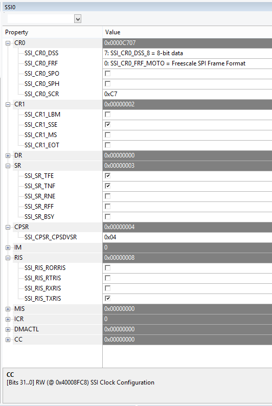
I began by trying to interface with a micro SD card using the sd_card example from the "DK" board. After a long series of debugging, I found that there is no signal on the oscilloscope when calling SSIDataPut (on either the DO pin or the SCLK pin). This is the problem I am currently running into. The real puzzling part is that there was one instance where I was able to read the contents of the SD card without problems, and one other time where I was seeing a signal on the oscilloscope, but was getting FR_DISK_ERR rather than the usual FR_NOT_READY.

I assumed this may be due to some changes I made to the circuit. Now I am simply using the spi_master example, with no changes. Still no signal when calling SSIDataPut. Although I do see that the pins drop from something like .5V to 0V when initializing.

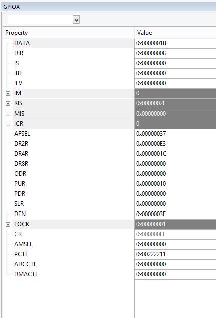
Using the same pins in both cases: PA2-5

Any guidance would be appreciated. Has anyone else encountered something like this recently? I've done a quick search and saw similar posts from before but without definitive solutions.

  • Hello Scott,

    I have forwarded this post to my colleague who should get in touch with you shortly.

    Thanks,
    Sai
  • It proves helpful - always - if posters include their, "Peripheral Set-Up & Configuration" code. Most always - error in that peripheral set-up - silences those pins.

    As you report (some) past success you'd help yourself if you could recount those changes made to that past, working code.
  • Hello Scott,

    Which EVM are you using DK-TM4C123 or DK-TM4C129x?

    Regards
    Amit
  • I am using an EK-TM4C123GXL. At first, I used the sd card example code from the DK-TM4C123G, which appears to have the same pin assignments Port A 2-5 for SSI0. Currently, I simplified everything to just using the SPI peripheral example. Still the same pin assignments PA2-5.  

    I have had a few instances of it working with the sd card. I think possibly on the introduction of a pull up resistor on one pin or another. (I've tried various combinations again) I suspect there may be something unstable. So right now I just want to see some signal on the SPI pins. 

    It is more likely there is something wrong with the circuit than the something wrong with the code, but I see that the ground pin is connected so I am expecting at least some sort of a signal on the SPI pins, unless I am missing something....

    The set up code is as follows, it is unchanged from the spi_master.c example.

        //
        // The SSI0 peripheral must be enabled for use.
        //
        SysCtlPeripheralEnable(SYSCTL_PERIPH_SSI0);
    
        //
        // For this example SSI0 is used with PortA[5:2].  The actual port and pins
        // used may be different on your part, consult the data sheet for more
        // information.  GPIO port A needs to be enabled so these pins can be used.
        // TODO: change this to whichever GPIO port you are using.
        //
        SysCtlPeripheralEnable(SYSCTL_PERIPH_GPIOA);
    
        //
        // Configure the pin muxing for SSI0 functions on port A2, A3, A4, and A5.
        // This step is not necessary if your part does not support pin muxing.
        // TODO: change this to select the port/pin you are using.
        //
        GPIOPinConfigure(GPIO_PA2_SSI0CLK);
        GPIOPinConfigure(GPIO_PA3_SSI0FSS);
        GPIOPinConfigure(GPIO_PA4_SSI0RX);
        GPIOPinConfigure(GPIO_PA5_SSI0TX);
    
        //
        // Configure the GPIO settings for the SSI pins.  This function also gives
        // control of these pins to the SSI hardware.  Consult the data sheet to
        // see which functions are allocated per pin.
        // The pins are assigned as follows:
        //      PA5 - SSI0Tx
        //      PA4 - SSI0Rx
        //      PA3 - SSI0Fss
        //      PA2 - SSI0CLK
        // TODO: change this to select the port/pin you are using.
        //
        GPIOPinTypeSSI(GPIO_PORTA_BASE, GPIO_PIN_5 | GPIO_PIN_4 | GPIO_PIN_3 |
                       GPIO_PIN_2);
    
        //
        // Configure and enable the SSI port for SPI master mode.  Use SSI0,
        // system clock supply, idle clock level low and active low clock in
        // freescale SPI mode, master mode, 1MHz SSI frequency, and 8-bit data.
        // For SPI mode, you can set the polarity of the SSI clock when the SSI
        // unit is idle.  You can also configure what clock edge you want to
        // capture data on.  Please reference the datasheet for more information on
        // the different SPI modes.
        //
    #if defined(TARGET_IS_TM4C129_RA0) ||                                         \
        defined(TARGET_IS_TM4C129_RA1) ||                                         \
        defined(TARGET_IS_TM4C129_RA2)
        SSIConfigSetExpClk(SSI0_BASE, ui32SysClock, SSI_FRF_MOTO_MODE_0,
                           SSI_MODE_MASTER, 1000000, 8);
    #else
        SSIConfigSetExpClk(SSI0_BASE, SysCtlClockGet(), SSI_FRF_MOTO_MODE_0,
                           SSI_MODE_MASTER, 1000000, 8);
    #endif
    
        //
        // Enable the SSI0 module.
        //
        SSIEnable(SSI0_BASE);

  • Hello Scott

    To use the SPI interface for SD Card, the FSS Pin has to be configured as a GPIO and controlled before and after a transaction. TivaWare 2.1.2.111 has the following path D:\ti\TivaWare_C_Series-2.1.2.111\third_party\fatfs\port where you can see how the FSS pin needs to be configured as a GPIO and controlled for communicating with the SD Card

    Regards
    Amit
  • In the sd card case, I can see that the FFS pin changes value when the SELECT and DESELECT functions are called. However I still do not see any changes on the TX and CLK pins when SSIDataPut is called.
  • Hello Scott

    Can you check which port file is being used in your design. It may be that the incorrect SSI and Pins have been configured in the port file?

    Regards
    Amit
  • by port file, are you referring to the pin-map.h file? I can see that I am using:

    #ifdef PART_TM4C123GH6PM
    
    #define GPIO_PA0_U0RX           0x00000001
    #define GPIO_PA0_CAN1RX         0x00000008
    
    #define GPIO_PA1_U0TX           0x00000401
    #define GPIO_PA1_CAN1TX         0x00000408
    
    #define GPIO_PA2_SSI0CLK        0x00000802
    
    #define GPIO_PA3_SSI0FSS        0x00000C02
    
    #define GPIO_PA4_SSI0RX         0x00001002
    
    #define GPIO_PA5_SSI0TX         0x00001402
    
    #define GPIO_PA6_I2C1SCL        0x00001803
    #define GPIO_PA6_M1PWM2         0x00001805
    
    #define GPIO_PA7_I2C1SDA        0x00001C03
    #define GPIO_PA7_M1PWM3         0x00001C05

    rvmdk PART_TM4C123GH6PM TARGET_IS_TM4C123_RB1 is defined under Options for Target -> C/C++ tab. However I had not considered the possibility of some included file causing a conflict. I will try creating a fresh project with only the spi_master.c file, as oppose to replacing my main.c file and still compiling the rest of the .c files in my project. 

  • *accidental double post, deleted

  • Hello Scott,

    By port I meant which of the files from the directory

    D:\ti\TivaWare_C_Series-2.1.2.111\third_party\fatfs\port

    is being imported and used in your project.

    Regards
    Amit
  • I am using mmc-dk-tm4c123g.c
  • Hello Scott

    The initialization looks correct. The next thing is from the IDE can you take a register dump of the GPIO A Registers and SSI 0 Registers when the error message is printed, to check if there is some inadvertent configuration change.

    Also check if you can toggle the IO's manually by configuring it in GPIO Mode. This will help establish if the IO's are working correctly.

    Regards
    Amit
  • Everything seems to be right as far as I can see... I did notice that the mmc file did not contain the pin multiplexing set up code. i.e

    GPIOPinConfigure(GPIO_PA2_SSI0CLK);
    GPIOPinConfigure(GPIO_PA3_SSI0FSS);
    GPIOPinConfigure(GPIO_PA4_SSI0RX);
    GPIOPinConfigure(GPIO_PA5_SSI0TX);

    but adding/removing that doesn't appear to make a difference. (This was done in the power_on function) I assume this is because there is only one alternate function available on those pins. 

    static
    void send_initial_clock_train(void)
    {
        unsigned int i;
        uint32_t ui32Dat;
    
        /* Ensure CS is held high. */
        DESELECT();
    
        /* Switch the SSI TX line to a GPIO and drive it high too. */
        ROM_GPIOPinTypeGPIOOutput(SDC_GPIO_PORT_BASE, SDC_SSI_TX);
        ROM_GPIOPinWrite(SDC_GPIO_PORT_BASE, SDC_SSI_TX, SDC_SSI_TX);
    		ROM_GPIOPinWrite(SDC_GPIO_PORT_BASE, SDC_SSI_TX, 0);					 	//added this
        ROM_GPIOPinWrite(SDC_GPIO_PORT_BASE, SDC_SSI_TX, SDC_SSI_TX); 	//added this
    	
        /* Send 10 bytes over the SSI. This causes the clock to wiggle the */
        /* required number of times. */
        for(i = 0 ; i < 10 ; i++)
        {
            /* Write DUMMY data. SSIDataPut() waits until there is room in the */
            /* FIFO. */
            SSIDataPut(SDC_SSI_BASE, 0xFF);
    
            /* Flush data read during data write. */
            SSIDataGet(SDC_SSI_BASE, &ui32Dat);
        }
    
        /* Revert to hardware control of the SSI TX line. */
        ROM_GPIOPinTypeSSI(SDC_GPIO_PORT_BASE, SDC_SSI_TX);
    }

    I added the 2 lines to set the TX pin to 0 and back to 1, and this is clearly visible on the oscilloscope.  

    I noticed register DR does not seem to clear after being written to. I'm not sure if this behavior is correct.

  • Hello Scott,

    Can you please publish the GPIO configuration as well?

    Regards
    Amit
  • static
    void power_on (void)
    {
        /*
         * This doesn't really turn the power on, but initializes the
         * SSI port and pins needed to talk to the card.
         */
    
        /* Enable the peripherals used to drive the SDC on SSI */
        ROM_SysCtlPeripheralEnable(SDC_SSI_SYSCTL_PERIPH);
        ROM_SysCtlPeripheralEnable(SDC_GPIO_SYSCTL_PERIPH);
    
    //    GPIOPinConfigure(GPIO_PA2_SSI0CLK);
    //    GPIOPinConfigure(GPIO_PA3_SSI0FSS);
    //    GPIOPinConfigure(GPIO_PA4_SSI0RX);
    //    GPIOPinConfigure(GPIO_PA5_SSI0TX);
    	
        /*
         * Configure the appropriate pins to be SSI instead of GPIO. The FSS (CS)
         * signal is directly driven to ensure that we can hold it low through a
         * complete transaction with the SD card.
         */
        ROM_GPIOPinTypeSSI(SDC_GPIO_PORT_BASE, SDC_SSI_TX | SDC_SSI_RX | SDC_SSI_CLK);
        ROM_GPIOPinTypeGPIOOutput(SDC_GPIO_PORT_BASE, SDC_SSI_FSS);
    
        /*
         * Set the SSI output pins to 4MA drive strength and engage the
         * pull-up on the receive line.
         */
        MAP_GPIOPadConfigSet(SDC_GPIO_PORT_BASE, SDC_SSI_RX, GPIO_STRENGTH_4MA, GPIO_PIN_TYPE_STD_WPU);
        MAP_GPIOPadConfigSet(SDC_GPIO_PORT_BASE, SDC_SSI_CLK | SDC_SSI_TX | SDC_SSI_FSS, GPIO_STRENGTH_4MA, GPIO_PIN_TYPE_STD);
    
        /* Configure the SSI0 port */
        ROM_SSIConfigSetExpClk(SDC_SSI_BASE, ROM_SysCtlClockGet(), SSI_FRF_MOTO_MODE_0, SSI_MODE_MASTER, 50000, 8); //changed from 400000
        ROM_SSIEnable(SDC_SSI_BASE);
    
        /* Set DI and CS high and apply more than 74 pulses to SCLK for the card */
        /* to be able to accept a native command. */
        send_initial_clock_train();
    
        PowerFlag = 1;
    }

  • Hello Scott

    The configuration looks correct. Now to be able to test it on my side, I would require the .out file so that I can run it on a EK-TM4C123GXL and see what the issue is....

    Regards
    Amit
  • Hi Amit.

    I do see an output for the pins on the oscilloscope now. I am using an USB oscilloscope and the edge triggering settings may have been messed up before. The sd_card program is still having issues. It appears that the DO/Rx pin is not changing correctly. However I've recently received the DK-TM4C123GXL board I ordered, and it works without any problems, so I will continue testing on that. If I find out exactly what is going wrong for the EK-TM4C123GXL board to communicate with the sd_card, I will be sure to update. Thank you so much, I appreciate your help through all of this.
  • Hello Scott,

    OK. Let us know how the debug goes. If in case nothing shows up, let us know which SD Card booster pack it is and may be I can help with one of my own audio reference designs which has a sd card

    Regards
    Amit