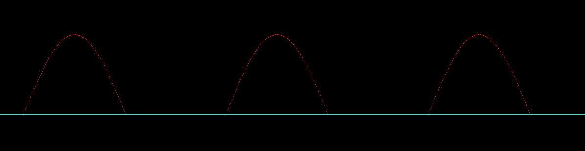
I am trying to sample 2 signals coming in on Channels 0 (PE3) and Channel 1 (PE2). I am currently send the same signal to both channels. However the signal from channel 0 has a lower amplitude. When I just sample channel 0 using sample sequencer 1, I don't have this issue.
Below is the code:
#include <stdbool.h>
#include <stdint.h>
#include "inc/hw_memmap.h"
#include "driverlib/adc.h"
#include "driverlib/gpio.h"
#include "driverlib/pin_map.h"
#include "driverlib/sysctl.h"
#include "driverlib/uart.h"
#include "utils/uartstdio.h"
#include "driverlib/adc.h"
#include "inc/tm4c123gh6pm.h"
#include "driverlib/timer.h"
#include "driverlib/interrupt.h"

float Voltage;
uint32_t pui32ADC0Value[2];


void
InitConsole(void)
{

    SysCtlPeripheralEnable(SYSCTL_PERIPH_GPIOA);
    GPIOPinConfigure(GPIO_PA0_U0RX);
    GPIOPinConfigure(GPIO_PA1_U0TX);
    SysCtlPeripheralEnable(SYSCTL_PERIPH_UART0);
    UARTClockSourceSet(UART0_BASE, UART_CLOCK_PIOSC);
    GPIOPinTypeUART(GPIO_PORTA_BASE, GPIO_PIN_0 | GPIO_PIN_1);
    UARTStdioConfig(0, 115200, 16000000);
}

int
main(void)
{

    uint32_t ui32Period;
    //Set Timer0
    SysCtlClockSet(SYSCTL_SYSDIV_2_5|SYSCTL_USE_PLL|SYSCTL_XTAL_16MHZ|SYSCTL_OSC_MAIN);
    SysCtlPeripheralEnable(SYSCTL_PERIPH_TIMER0);
    TimerConfigure(TIMER0_BASE, TIMER_CFG_PERIODIC);
    ui32Period = ((SysCtlClockGet()/1000) );
    TimerLoadSet(TIMER0_BASE, TIMER_A, ui32Period-1);
    IntEnable(INT_TIMER0A);
    TimerIntEnable(TIMER0_BASE, TIMER_TIMA_TIMEOUT);
    IntMasterEnable();
    TimerEnable(TIMER0_BASE, TIMER_A);

    InitConsole();

    SysCtlPeripheralEnable(SYSCTL_PERIPH_ADC0);
    SysCtlPeripheralEnable(SYSCTL_PERIPH_GPIOE);

    GPIOPinTypeADC(GPIO_PORTE_BASE, GPIO_PIN_3);
    GPIOPinTypeADC(GPIO_PORTE_BASE, GPIO_PIN_2);

    ADCSequenceConfigure(ADC0_BASE, 1, ADC_TRIGGER_PROCESSOR, 0);
    ADCSequenceStepConfigure(ADC0_BASE, 1, 0, ADC_CTL_CH0 ); //Sequencer Step 1: Samples Channel PE3
    ADCSequenceStepConfigure(ADC0_BASE, 1, 1, ADC_CTL_CH1); //Sequencer Step 2: Samples Channel PE2
    ADCSequenceStepConfigure(ADC0_BASE, 1, 2, ADC_CTL_CH2); //Sequencer Step 3: Unconnected pin
    ADCSequenceStepConfigure(ADC0_BASE, 1, 3, ADC_CTL_CH3 | ADC_CTL_IE | ADC_CTL_END); //Step 4: Unconnected pin

    ADCSequenceEnable(ADC0_BASE, 1);
    ADCIntClear(ADC0_BASE, 1);
    ADCIntEnable(ADC0_BASE, 1);

    while(1){ }
}
void timer_ADC0(void)
{
ADCProcessorTrigger(ADC0_BASE, 1);
while(!ADCIntStatus(ADC0_BASE, 1, false)) ;
ADCSequenceDataGet(ADC0_BASE,1, pui32ADC0Value );
Voltage = (pui32ADC0Value[0]*3.3/4096);
}
void
Timer0IntHandler(void) {
    TimerIntClear(TIMER0_BASE,TIMER_TIMA_TIMEOUT);
    timer_ADC0();
    UARTprintf("%4d,%4d\r",pui32ADC0Value[0],pui32ADC0Value[1]);
}
Plot of Channel 0, Followed by Plot of Channel 1