This thread has been locked.

If you have a related question, please click the "Ask a related question" button in the top right corner. The newly created question will be automatically linked to this question.

Over-length pulse sometimes generated when PWM period changed

Other Parts Discussed in Thread: TM4C1294NCPDT, MOTORWARE

I'm trying to use the PWM peripheral to generate pulse streams of varying period and a duty cycle of approx 50%. I have code which works most of the time, but sometimes when I change the period, I get an over-length pulse at the point of change - a pulse which is longer than the correct pulse for either the previous or the new period.
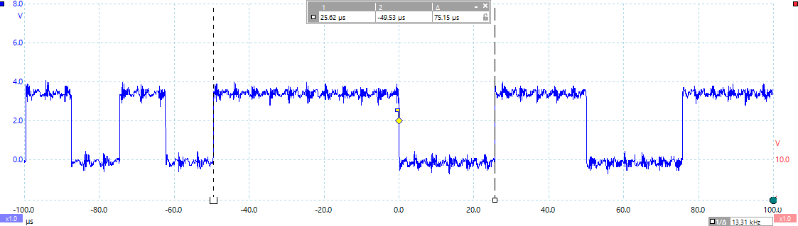
A specific example:

  • going from 25.05us to 50.01us period (from 12.5 to 25 us pulse length), I sometimes get a high pulse of 49.5us (see scope trace below)
  • going from 50.01us to 25.05us period (from 25 to 12.5 us pulse length), I sometimes get a high pulse of 37.4us.

In one run of 1000 changes of period, I saw the over-length pulse 14 times.

I'm using a PWM clock divisor of 64 (PWM_CC = 0x105), and the changes to the LOAD and CMP registers of the PWM are made in "Globally Synchronized" mode ("Updates to the register are delayed until the next time the counter is 0 after a synchronous update has been requested through the PWMCTL register"). As I understand it, this mode should mean that the LOAD and CMP registers both get updated at the same time, but even if they did not I can't see why I should sometimes get a period of over 62us when changing between 25 and 50us.


The code which is updating the PWM timings is:


HWREG(PWM0_BASE + pwm_gen_id + PWM_O_X_LOAD) = period - 1; // set PWM period
HWREG(PWM0_BASE + pwm_gen_id + PWM_O_X_CMPA) = period >> 1; // set PWM duty cycle to 50%
HWREG(PWM0_BASE + pwm_gen_id + PWM_O_X_GENA) = 0x8c; // drive pwm output high on load and low on CMPAdn
HWREG(PWM0_BASE + PWM_O_CTL) = pwm_gen_bit; // Synchronize pending PWM register changes the next time the counter becomes zero


and the state of the relevant PWM registers when running is

PWMCTL=0
PWMSYNC=0
PWMENABLE=0x55
PWMENUPD=0x2222
PWM0CTL=0xfd
PWM0CMPB=0
PWM0GENA=0x8c

and either

PWM0LOAD=0x5d, PWM0CMPA=0x2f

or

PWM0LOAD=0x2e, PWM0CMPA=0x17

The is on a TM4C1294NCPDT with silicon revision 3, so the only documented PWM bug is PWM#04, which is not relevant as I am not using any PWM interrupts.

I'm starting to feel arrogant enough to suspect a bug in the PWM peripheral, so will someone please tell me how I'm being dumb here and it's my fault for not using it properly?

Thanks,

Michael

(I also saw wrong-length first pulses when starting the pulse stream running, either by writing to PWMENABLE or by changing PWM0GENA from 0x80 to 0x8c - this may be related to the above issue. But let's start with the period-change issue as it is simpler to understand.)

  • I've checked that when the update-timings code is run, the variables are set correctly: pwm_gen_id is 0x40 and pwm_gen_bit is 1, which I think is correct as I am using PWM output 0.

    The write to the GENA register is only needed on the first call, to enable the pulse generation, so I also tried preceding it by

    if (HWREG(PWM0_BASE + pwm_gen_id + PWM_O_X_GENA) != 0x8c)

    to see if the problem is caused by that write: but it made no apparent difference.

  • Hello Michael,

    Can you simplify the code to a PWM code and reproduce the issue? Once that is done, please attach the CCS project so that we can check on our side what the issue is!!!

    Regards
    Amit
  • OK, here is an standalone example project.  It generates a PWM output on PF0, which should switch cleanly between 50us and 25us period.

    This seems to only show the incorrect waveform when switching from 25us to 50us period and not the other way.  I set my scope to trigger on high pulses of over 26us to catch the errors.

    The same incorrect waveform output happens if CMPA is written before LOAD.

    pwm_issue.zip

    I have realised that both types of incorrect waveform could be explained if the CMPA register is sometimes getting updated on the cycle after LOAD.  But if I've correctly enabled and used 'global synchronisation' mode, they should be getting updated at the same time.

    Michael

  • Hello Michael

    Thanks for the project. I am able to reproduce the issue on my side and I believe it is due to the PWM Clock Divider. I would need some more debug on this issue

    Regards
    Amit
  • Working at another (large) semi firm - we were advised "not" to confine our test/verifies to any, "special treatment and/or handled pins." PF0 is "such a pin" upon 4C123 - I don't know about user's "4C129." It may prove useful to test to see if this issue "generalizes" to other pins - and other ports. (ideally "standard" pins)

    On a related note - firm/I have never/ever been able to note a "solid" difference between "Global & Local" Sync.   Amit's made the effort to past explain - yet our tests cannot detect any difference.   A tested/proven code example (via the API) would prove useful - I believe poster's report - and my firm's notice - (may) have identified the "tip" of a "mal-performing, PWM iceberg..."

  • Hi matten,

    May have seen similar behavior with the LM3S when triggering ADC in down count using PWM_TR_CNT_BD -- though not exactly the same issue. Sometimes the generator outputs A/B do not change state ignoring the NEW load value if greater comparator match values are asserting The pulse width is extended as a result (given below). Even worse when dead band enabled, A out is inverted and becomes B out by the delay time and the ignored greater matching count values never get loaded.

    23.3.3 PWM Comparators

    Each PWM generator has two comparators that monitor the value of the counter; when either comparator matches the counter, they output a single-clock-cycle-width High pulse, labeled "cmpA" and "cmpB" in the figures in this chapter. When in Count-Up/Down mode, these comparators match both when counting up and when counting down, and thus are qualified by the counter direction signal. These qualified pulses are used in the PWM generation process. If either comparator match value is greater than the counter load value, then that comparator never outputs a High pulse.

  • BP101 said:
    If either comparator match value is greater than the counter load value, then that comparator never outputs a High pulse.

    Your sentence in highlight is difficult to relate to this thread.  

    Poster reports, "Over Length" pulse - not a, "Loss of High Pulse" as you highlight!

  • Hello cb1,

    I am able to reproduce the issue on other pins as well, so it is not limited to PF0, but the issue seems to be a function of the PWM

    Regards
    Amit
  • Thank you, Amit.

    Perhaps this exercise may enable the (real) probing & "proof" of Sync Local vs. Sync Global. (we've tried - cannot detect any difference)
  • Hello cb1

    Surely, I would.

    Regards
    Amit
  • Seemingly and inversely - the comparator match value during large frequency transitions is greater than the new frequency load value so the pulse stays high during the update. That can be seen trigging the ADC from comparator B down - expected period samples are skipped.
  • Hello Michael,

    I can now confirm that the issue is a bug in the PWM module. There is a condition where the generator timer may still count with the old load value, but the new comparator value gets loaded causing the high pulse width as shown in the example code.

    I have asked for an errata submission.

    From a workaround perspective, the suggested workaround would be to use the interrupt status to write the value of the new load and comparator, clear the raw status bit for Count of 0 and then write the Global Sync bit.

    Regards
    Amit
  • Hi Amit,

    Curious if a timer enabled PWM with CCP event interrupts has the same problem. Find it odd poster has used the PWM peripheral in down count mode producing two PWM outputs. Curious if the PWM peripheral configured in up/down count mode has similar issue described?
  • Hello BP101

    The timer based PWM has a different architecture that the PWM module. So by difference "NO", but unless it is proven otherwise in a small dedicated test that this may happen.

    Regards
    Amit
  • Hi Amit,

    Very nice find by both you and Matten (congratulations on that errata #) and you made a SW work around -- even better yet! :)
  • Hello BP101

    Let us wait for Michael, to confirm that the SW workaround helps

    Regards
    Amit
  • Hello Amit,

    I'm afraid it's not very clear to me what you are suggesting as a workaround.

    Amit Ashara said:
    the suggested workaround would be to use the interrupt status to write the value of the new load and comparator, clear the raw status bit for Count of 0 and then write the Global Sync bit.

    I can see that the count zero interrupt flag (PWMnISC bit 0) can be set up to give a "PWM counter has passed through zero" indication without actually generating an interrupt, by setting bit 0 in PWMnINTEN; writing PWMnISC with bit 0 set will clear the flag and it will be set again when the counter passes through zero.
    Am I correct to say that your suggested workaround is to write the new values to PWMnLOAD and PWMnCMPx, then wait for the PWM counter to pass through zero (using the method above) before writing to PWMSYNC to trigger the register update?

    Has anyone at TI investigated the scope of this issue? I'm wondering whether the problem only applies to the LOAD register, or could it also occur on other registers configured for "Globally Synchronized" update, such as the CMPA/B, GENA/B and PWMENABLE registers?

    Thanks,

    Michael

  • Hello Michael,

    Yes, it can occur in the other registers, based on the timing of events.

    Regards
    Amit
  • Hello Michael

    And yes, that is the WA being suggested as well.

    Regards
    Amit
  • Hi Matten,

    Might you consider a PWM timer configured to interrupt for CCP event (rise or fall) can be chained and all chained timer clocks made synchronous. The main destructive errata is for edge count up count mode, the down count CCP interrupt we use to change fan speed duty cycle works perfectly and can bump PWM duty from 1% to 100% in a single cycle.
  • Hi Amit,

    While on topic of errata can you perhaps verify PWM0n dead band generator (pwmB) seemingly produces PWMnDBFALL output when disabled. Chuck was assisting us on this issue and refused to go further without example SW, (pwm) needs a rewrite to run on TM4C1294 launch pad.

  • May we note that ALL posters responding to that, "Shape-Shifting" torrent made such, "Decline" - not just Chuck... There's no way any "down the road reader" can benefit from that meandering hobgob...
  • Hello BP101

    Without a simple test code that can be used to check the issue, it would be rather difficult

    Regards
    Amit
  • How is peripheral Errata ever the issue for a customer to uncover and wouldn't that kind of stance possibly lead to unnecessary law suites?
  • BP,

    You are correct in that it is not the expectation that a customer uncover an errata. To my knowledge and with the evidence so far presented, no errata has been uncovered. Certainly you are observing some behavior that you did not expect, but there has been no conclusions that this is an errata by anyone other than perhaps yourself. Note that I am not stating this maliciously but as a matter of fact based on those that have contributed to the discussion.

    It is very common for us to ask for code that demonstrate the issue since it can either confirm your observations and thus an errata, allow us to confirm that the assumed use is not in accordance with the expected use of the IP which will allow us to clarify and limit it in some way, or that there is issue in the interpretation of the results, again, allowing us to clarify. Without such detail/resources, we tend to write our test cases in the way that we understand them to be properly used/implemented and therefore often cannot reproduce the issue. This leads to the search for the proverbial needle in a haystack.
  • BP,

    Please don't hijack this thread to get your point across about another thread. You are taking this discussion off course on a subject that is unrelated to the original posters problem.

    And, please note that an errata is not an errata until it is confirmed. TI has not confirmed any issues related to your post and even you admittedly speculate that something is probably happening in the motorware loop/software causing an issue. Until we have a test case to confirm the behavior, we cannot and will not label this an errata. At this point it is simply the observation of 1 thread on E2E based on 1 specific implementation.

    Please take further discussion back to the original thread!
  • Sorry Chuck not sure how these posts were cross treaded however not by me!

    Seems you posted in this thread but it also showed in the original thread I replied to.

  • So I have retracted the comments made incorrectly this thread so too please show equally the same kindness. The question of possible errata was asked to Amit, you then inappropriately responded to a question asked of him. Prior posting to other thread I have never heard of Chuck Davenport this forum and suspect you are a fairly new to help out Amit's excessively heavy load.

    BTW: Search the forum posts, issue in other thread was reported years ago by myself and others claiming similar results.
  • BP,

    I never asked you to "delete" edit or remove your posts. Simply asked you to redirect the subject back to the original thread.

    It's not for you to judge my capability to support nor is it for me to prove. Fact is, I am an assigned moderator to this Forum and, therefore, can and will respond when appropriate. To whom you asked if this is an errata is irrelevant. I was responding to a post where you repeatedly referred to the "errata" like it were set in stone, confirmed, and published for the masses. This, in my mind needed correction and a note indicating that it was not, in fact, an errata.
  • As stated I was not attempting to as your stating to hijack this thread. Quite obviously I was unaware nor have ever had a moderator interject his view in Response to a question asked to another poster. That seemingly violates confidentiality rules and if anyone was hijacking a thread perhaps it was you and not I. Obviously I responded to your question believing it was posted in the thread it was thought to be intended for. From my view point that was a devious action on your part and I was made the sacrificial lamb.

  • BTW: I agreed with Chuck's view that errata was reserved for documented and confirmed incorrect peripheral behavior and have removed the word from all posts in the thread this poster believed he was invoking when responding to moderator Chuck.

    Glad to finally meet a thread moderator everyone have a great memorial weekend.
  • Confidentiality rules!!? Surely you jest.

    I also saw your posts as a hijack attempt.

    Robert
  • I've tried the suggested workaround and it makes a big difference: the over-length pulse now happens much more frequently (possibly every time), and on both increasing and decreasing PWM period!

    I've attached the modified project, but all I have changed is to add, in the initialisation stage:

    HWREG(PWM0_BASE + PWM_GEN_0 + PWM_O_X_INTEN) = PWM_X_INTEN_INTCNTZERO;
    

    and before each write to PWMCTL:

    HWREG(PWM0_BASE + PWM_GEN_0 + PWM_O_X_ISC) = PWM_X_ISC_INTCNTZERO;
    while (!(HWREG(PWM0_BASE + PWM_GEN_0 + PWM_O_X_ISC) & PWM_X_ISC_INTCNTZERO)) { }

    Which is what I understood the suggested workaround to be.

    Maybe I have misunderstood or mis-implemented the workaround - could you just post the code you used to verify the workaround at TI?

    Michael

    pwm_issue_wa1.zip

  • Confidential messaging to an intended recipient is not a jest it was expected adding later confusion as to what thread this poster had responded to. It can't be consider hijacking when I previously made suggestions as possible event cause and later discovered errata.

    Not sure how suggesting poster might also try a Timer versus PWM peripheral constitutes a hijacking attempt when an errata had been confirmed and WA (suggested). Point was WA does not remove HW errata. Redacted post this thread was merely asking Amit to assist Chuck in rewrite (pwm project for TM4C1294) yet another possible though not confirmed by TI representative as HW errata in the lab.
  • Hello Michael,

    What you implemented is correct. It may have been a misinterpretation on my side. The divided by N clock for the PWM may be causing the issue. So I mad a change to the code above. Replacing it with

    HWREG(PWM0_BASE + PWM_GEN_0 + PWM_O_X_ISC) = PWM_X_ISC_INTCMPAD;
    while (!(HWREG(PWM0_BASE + PWM_GEN_0 + PWM_O_X_ISC) & PWM_X_ISC_INTCMPAD)) { }

    Does not show the issue on my side.

    Basically the load must be done with the Comparison A/B down (if using down mode).

    Regards
    Amit
  • Chuck was only responding to your public utterances.

    Robert
  • Yes, that does seem to work, thanks!
    I hope that in the fullness of time a detailed description of the issue will be published, so that users of the PWM peripheral can engineer the most suitable workaround for their application, as well as helping us understand all the circumstances in which a workaround may be required.
    Regards,
    Michael
  • Again If offering an alternate solution responding a posters issue constitutes hijacking then many in this forum are equally guilty of that. Including anyone that attempts to redirect a posters issue from achieving a rapid solution by giving unwarranted instruction to alter course based on a premise their logic is more sound than yours.

  • Hello Matten,

    Yes, that would need to be done.

    Regards
    Amit