Other Parts Discussed in Thread: TM4C123GH6PM
Hello,
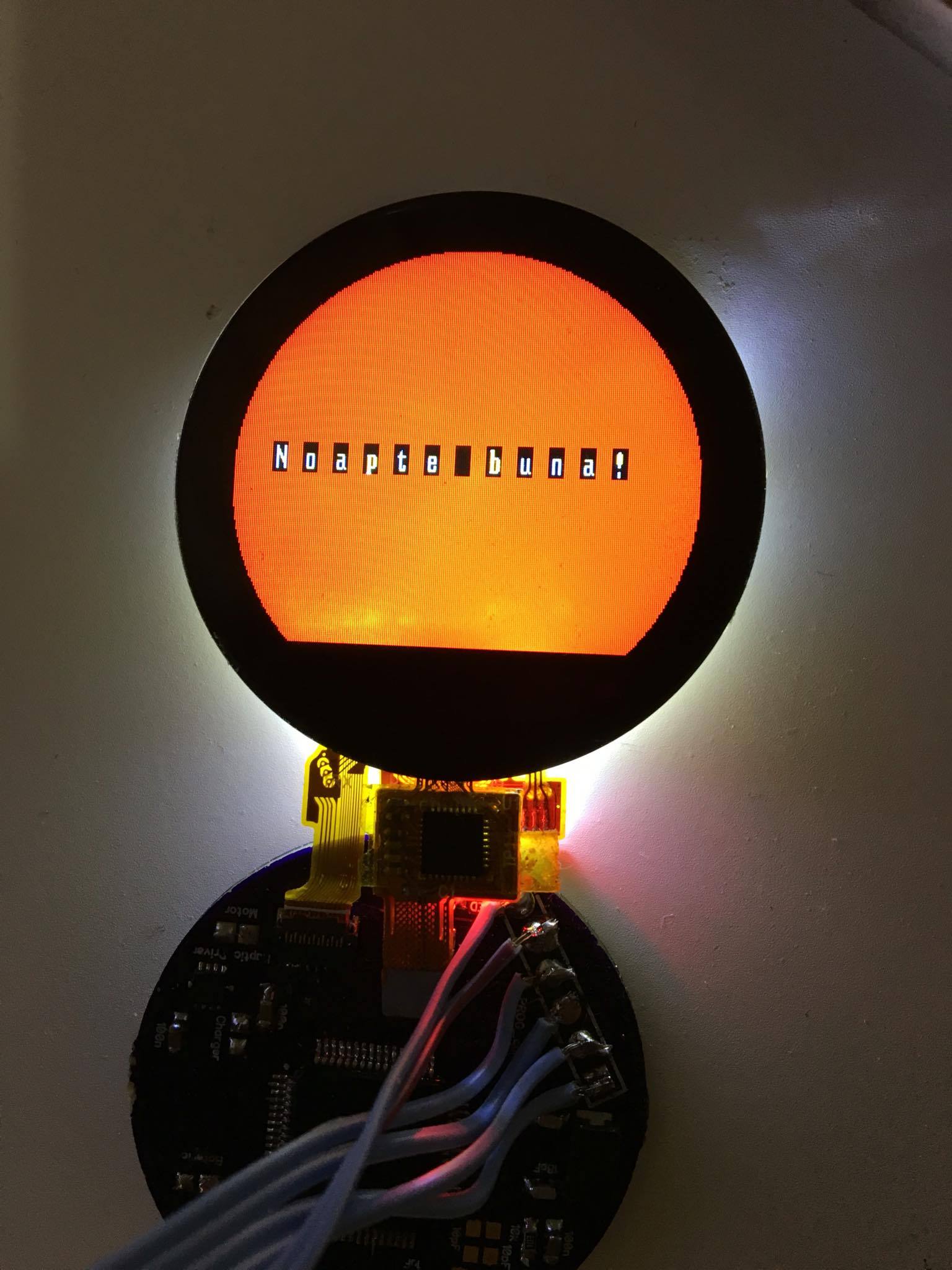
I am trying to interface a TM4C123GH6PM with a LCD (that also have a touchscreen), its a chinese round tft. Its driver is ST7789H2(https://cdn-reichelt.de/documents/datenblatt/A300/ST7789.pdf
Before today i wasn t able to see anything on the screen, what i did today it was modifying the next lines:
ROM_SysCtlClockSet(SYSCTL_SYSDIV_4 | SYSCTL_USE_PLL | SYSCTL_XTAL_16MHZ | SYSCTL_OSC_MAIN); here i change the SYSCTL_SYSDIV_2_5 to SYSCTL_SYSDIV_4.
Eliminate the while(SSIBusy(SSI3_BASE)){}; command from sending SPI commands/parameter functions.
And change the transmission frequency from 12Mhz to 1Mhz.
Thank you very much!
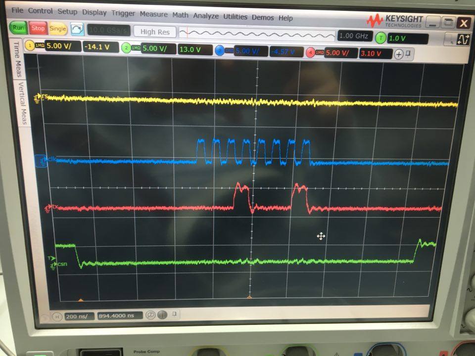
Sending a parameter:
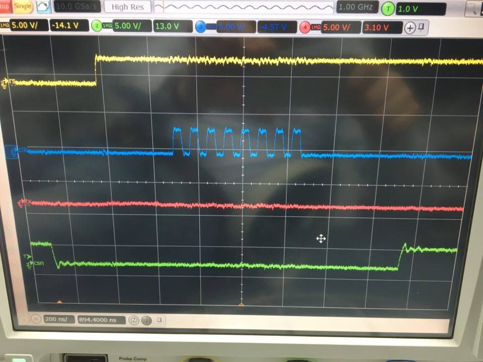
Sending a command:
HH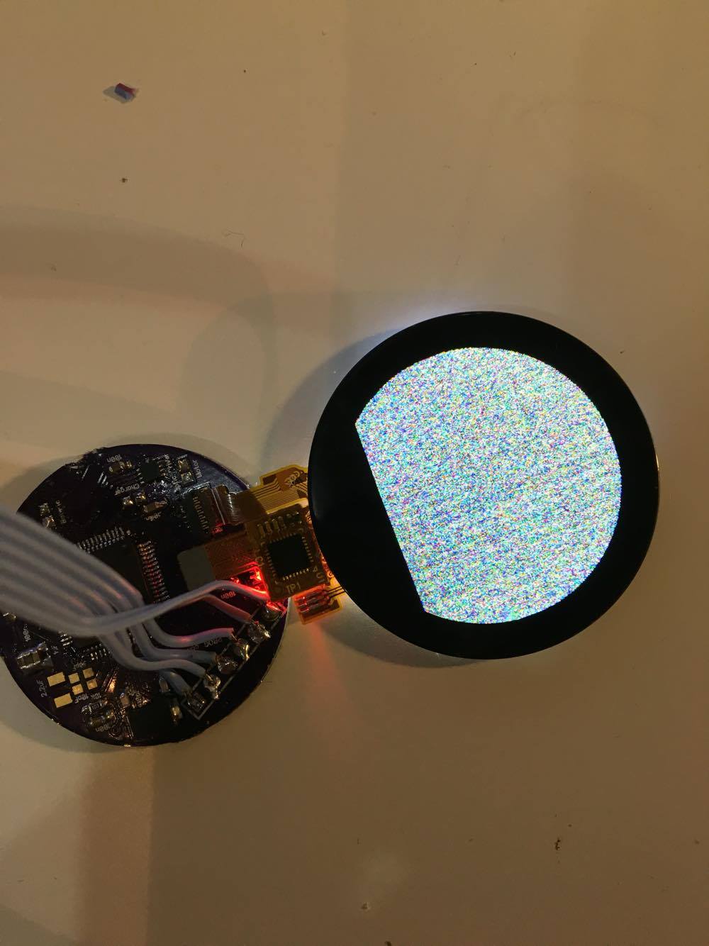
#include <stdint.h>
#include <stdbool.h>
#include <stdio.h>
#include <stdlib.h>
#include <string.h>
#include "timer_delay.h" // delay_ms(),delay_us()
#include "inc/hw_memmap.h"
#include "inc/hw_types.h"
#include "inc/hw_ints.h"
#include "driverlib/gpio.h"
#include "driverlib/sysctl.h"
#include "driverlib/interrupt.h"
#include "driverlib/rom.h"
#include "driverlib/gpio.h"
#include "driverlib/pin_map.h"
#include "driverlib/sysctl.h"
#include "driverlib/ssi.h"
#include "driverlib/interrupt.h"

#define SSI_CLK					GPIO_PIN_0
#define SSI_TX					GPIO_PIN_3
#define SSI_FSS					GPIO_PIN_1

#define LCD_RESET_HIGH()		ROM_GPIOPinWrite(GPIO_PORTD_BASE, GPIO_PIN_6, GPIO_PIN_6)// RESET  HIGH
#define LCD_RESET_LOW()			ROM_GPIOPinWrite(GPIO_PORTD_BASE, GPIO_PIN_6, 0)// RESET  LOW
#define LCD_RESET()         	LCD_RESET_HIGH();  delay_ms(50); LCD_RESET_LOW();  delay_ms(50); LCD_RESET_HIGH();

#define LCD_A0_HIGH()			ROM_GPIOPinWrite(GPIO_PORTD_BASE, GPIO_PIN_2, GPIO_PIN_2)// A0  HIGH
#define LCD_A0_LOW()			ROM_GPIOPinWrite(GPIO_PORTD_BASE, GPIO_PIN_2, 0)// A0  LOW

#define LCD_CS_HIGH()			ROM_GPIOPinWrite(GPIO_PORTD_BASE, GPIO_PIN_1, GPIO_PIN_1)// CS  HIGH
#define LCD_CS_LOW()			ROM_GPIOPinWrite(GPIO_PORTD_BASE, GPIO_PIN_1, 0)// CS  LOW

#define disp_y_size 208
#define disp_x_size 240
#define	COLOR_BLUE (uint16_t)(0xF800)
#define LEFT 0
#define RIGHT 9999
#define CENTER 9998

uint8_t	fch, fcl, bch, bcl;

typedef struct
{
	uint8_t* font;
	uint8_t x_size;
	uint8_t y_size;
	uint8_t offset;
	uint8_t numchars;
} _current_font;

_current_font	cfont;

int main(void) {

				SPI_Init();
				LCD_RESET();
delay_ms(500);
				LCD_CS_HIGH();
				LCD_A0_LOW();

				delay_ms(25);

				LCD_CS_HIGH();
				LCD_A0_LOW();
 ROM_GPIOPinTypeGPIOOutput(GPIO_PORTD_BASE,  GPIO_PIN_1);
 ROM_SysCtlPeripheralEnable(SYSCTL_PERIPH_GPIOB);
 ROM_GPIOPinTypeGPIOOutput(GPIO_PORTB_BASE,  GPIO_PIN_6);
 ROM_GPIOPinWrite(GPIO_PORTB_BASE, GPIO_PIN_6, GPIO_PIN_6);
 LCD_CS_HIGH();
 delay_ms(200);
 LCD_Init();
 fillScr(0xF800);
 ROM_SysCtlPeripheralEnable(SYSCTL_PERIPH_GPIOC);
ROM_GPIOPinTypeGPIOOutput(GPIO_PORTC_BASE,  GPIO_PIN_7);  //ledul
setColor(COLOR_BLUE);
delay_ms(1000);
fillRoundRect(10,10,200,200);
 while(1){
 //WriteCommand(0x11); //sleep out
	// delay_ms(100);
	// ROM_GPIOPinWrite(GPIO_PORTC_BASE, GPIO_PIN_7, GPIO_PIN_7);
	// delay_ms(100);
//ROM_GPIOPinWrite(GPIO_PORTC_BASE, GPIO_PIN_7, 0);
//drawPixel_Color(50,50,COLOR_BLUE);
//delay_ms(2000);
//WriteCommand(0x54);
//WriteParameter(0x20);
	// WriteCommand(0x2C);
//setColor(COLOR_BLUE);
//delay_ms(1000);
//fillRoundRect(10,10,200,200);
	 }
 }


void WriteParameter(unsigned char data)
{
	LCD_CS_LOW();	//select
	LCD_A0_HIGH(); // A0 high for data

	//while(SSIBusy(SSI3_BASE)){}; //STERGE!?!?!?
		 SSIDataPut(SSI3_BASE, data);
		// while(SSIBusy(SSI3_BASE)){};

		// delay_ms(1);
	LCD_CS_HIGH();	//unselect
}

void WriteCommand(unsigned char cmd)
{

	LCD_CS_LOW(); //select
	LCD_A0_LOW();// A0 low for commands
	//while(SSIBusy(SSI3_BASE)){};//STERGE!>!>!>
	SSIDataPut(SSI3_BASE, cmd);
//delay_ms(1);
	// while(SSIBusy(SSI3_BASE)){};
	LCD_CS_HIGH();	//unselect
	// d
}

void SPI_Init(){
	ROM_SysCtlClockSet(SYSCTL_SYSDIV_4 | SYSCTL_USE_PLL | SYSCTL_XTAL_16MHZ | SYSCTL_OSC_MAIN); //  80 Mhz
	//2.5 ERA INAINTE NU 4!!!
	bsp_timer_init();
			ROM_SysCtlPeripheralEnable(SYSCTL_PERIPH_SSI3);
			ROM_SysCtlPeripheralEnable(SYSCTL_PERIPH_GPIOD);
			ROM_GPIOPinTypeGPIOOutput(GPIO_PORTD_BASE,  GPIO_PIN_2 | GPIO_PIN_6); //  A0, RESETals Output
			ROM_GPIOPinWrite(GPIO_PORTD_BASE, GPIO_PIN_2, 0);// A0  LOW
			ROM_GPIOPinWrite(GPIO_PORTD_BASE, GPIO_PIN_6, GPIO_PIN_6);// RESET  HIGH
			ROM_GPIOPinConfigure(GPIO_PD0_SSI3CLK);//PB4 CLK
			ROM_GPIOPinConfigure(GPIO_PD3_SSI3TX); //PB7 MOSI
			ROM_GPIOPinConfigure(GPIO_PD1_SSI3FSS);//PB5 CS
			ROM_GPIOPinTypeSSI(GPIO_PORTD_BASE, SSI_CLK | SSI_TX | SSI_FSS);
					// Configure SSI2 // bis 12Mhz SPI-Takt ok, > 12Mhz bis... =25Mhz Spi-Takt
			ROM_SSIConfigSetExpClk(SSI3_BASE, SysCtlClockGet(), SSI_FRF_MOTO_MODE_0, SSI_MODE_MASTER, 1000000, 8);// 12,5Mhz
				delay_ms(100);
					ROM_SSIDisable(SSI3_BASE);// Enable the SSI module.
				delay_ms(100);
					ROM_SSIEnable(SSI3_BASE);
					ROM_GPIOPinWrite(GPIO_PORTD_BASE, GPIO_PIN_1, GPIO_PIN_1);// CS HIGH
}

void LCD_Init(){
	WriteCommand(0x11); //sleep out
	delay_ms(120);                //Delay 120ms0
delay_ms(10);
	WriteCommand(0x38); // AICI E ADAUGAT DE MINE // IDLE MODE OFF
	//delay_ms(10);
		WriteCommand(0x36); // Memory Data Access Controls
		//delay_ms(10);
		WriteParameter(0x00);
		//delay_ms(10);
		WriteCommand(0x3A); // Interface Pixel Format
		//WriteParameter(0x06);
		//delay_ms(10);
		WriteParameter(0x06); //setare noua
		//delay_ms(10);
		WriteCommand(0xB2); //: Porch Setting
		//delay_ms(10);
		WriteParameter(0x0C);
		//delay_ms(10);
		WriteParameter(0x0C);
		//delay_ms(10);
		WriteParameter(0x00);
		//delay_ms(10);
		WriteParameter(0x33);
		//delay_ms(10);
		WriteParameter(0x33);

		//delay_ms(10);
		WriteCommand(0xB7); //Gate Control
		//delay_ms(10);
		WriteParameter(0x35);

		//delay_ms(10);
		WriteCommand(0xBB); //VCOM Setting
		//delay_ms(10);
		WriteParameter(0x1A);
		//delay_ms(10);
		WriteCommand(0xC0); // LCM Control
		//delay_ms(10);
		WriteParameter(0x2C);

		//delay_ms(10);
		WriteCommand(0xC2); // VDV and VRH Command Enable
		//delay_ms(10);
		WriteParameter(0x01);

		//delay_ms(10);
		WriteCommand(0xC3); // VRH Set
		//delay_ms(10);
		WriteParameter(0x0B);
		//delay_ms(10);
		WriteCommand(0xC4); // VDV Set
		//delay_ms(10);
		WriteParameter(0x20);

		//delay_ms(10);
		WriteCommand(0xC6); //Frame Rate Control in Normal Mode
		//delay_ms(10);
		WriteParameter(0x0F);

		//delay_ms(10);
		WriteCommand(0xD0); // Power Control 1
		//delay_ms(10);
		WriteParameter(0xA4);
		//delay_ms(10);
		WriteParameter(0xA1);

		//delay_ms(10);
		WriteCommand(0x21); //Display Inversion On

		//delay_ms(10);
		WriteCommand(0xE0); //Positive Voltage Gamma Control
		//delay_ms(10);
		WriteParameter(0x00);
		//delay_ms(10);
		WriteParameter(0x19);
		//delay_ms(10);
		WriteParameter(0x1E);
		//delay_ms(10);
		WriteParameter(0x0A);
		//delay_ms(10);
		WriteParameter(0x09);
	//	delay_ms(10);
		WriteParameter(0x15);
		//delay_ms(10);
		WriteParameter(0x3D);
		///delay_ms(10);
		WriteParameter(0x44);
		//delay_ms(10);
		WriteParameter(0x51);
		//delay_ms(10);
		WriteParameter(0x12);
		//delay_ms(10);
		WriteParameter(0x03);
		//delay_ms(10);
		WriteParameter(0x00);
		//delay_ms(10);
		WriteParameter(0x3F);
		//delay_ms(10);
		WriteParameter(0x3F);
		//delay_ms(10);
		WriteCommand(0x29);
		//NEW ENTRY
	/*	WriteCommand(0x2A);// Column set
		WriteParameter(0x00);
		WriteParameter(0x00);
		WriteParameter(0x00);
		WriteParameter(0xEF); //NOWAY
		WriteCommand(0x2B);//Raw set
		WriteParameter(0x00);
		WriteParameter(0x00);
		WriteParameter(0x01);
		WriteParameter(0x3F); //NOWAY
		WriteCommand(0x13); // DISPLAY ON_ADDED 8mai
				WriteCommand(0x29);

//WriteCommand(0x2C); // Memory write*/
}

void fillScr(uint16_t color)
	{
		long n, i, j;
		i = (color >> 8);
		j = (color & 0xFF);
		setXY(0,0,disp_y_size,disp_x_size);
		WriteCommand(0x2C);

		for (n = 0; n < 49920; n++) {
			WriteParameter(i);
			WriteParameter(j);
		}


	}

void setXY(uint16_t x1,uint16_t y1, uint16_t x2, uint16_t y2)
	{


		WriteCommand(0x2A); //column
		WriteParameter(x1>>8);
		WriteParameter(x1);
		WriteParameter(x2>>8);
		WriteParameter(x2);
		WriteCommand(0x2B); //page
		WriteParameter(y1>>8);
		WriteParameter(y1);
		WriteParameter(y2>>8);
		WriteParameter(y2);
		WriteCommand(0x2C); //write

	}

void setBackColor(uint16_t color)
	{
		bch=(color>>8);
		bcl=(color & 0xFF);
	}

void WriteData_2_8(uint8_t VH,uint8_t VL)
{

	LCD_CS_LOW();   //select
	LCD_A0_HIGH();  // A0 high for data

	//while((SSI2_SR_R&SSI_SR_TNF)==0){};   // wait until transmit FIFO not full
	//SSI2_DR_R = VH;      // data out
	while(SSIBusy(SSI3_BASE)){};
		 SSIDataPut(SSI3_BASE, VH);


//	while((SSI2_SR_R&SSI_SR_TNF)==0){};   // wait until transmit FIFO not full
//	SSI2_DR_R = VL;      // data out
	//while(SSIBusy(SSI3_BASE)){};
		 SSIDataPut(SSI3_BASE, VL);

		 //delay_ms(1);

	LCD_CS_HIGH();	//unselect


}

void drawHLine(int x, int y, int l)
	{

		uint16_t i;

		if (l<0)
		{
			l = -l;
			x -= l;
		}
		setXY(x, y, x+l, y);

			for (i=0; i<l+1; i++)
			{
				WriteData_2_8(fch, fcl);
			}


	clrXY();
	}


void drawPixel(int x, int y)
	{

		setXY(x, y, x, y);
		setPixel((fch<<8)|fcl);
	clrXY();

	}

void setPixel(uint16_t color)
	{


		WriteData_16(color);


	}

void WriteData_16(uint16_t data) // 16 Bit
{

	LCD_CS_LOW();	//select
	LCD_A0_HIGH(); 	// A0 high for data

//	while((SSI2_SR_R&SSI_SR_TNF)==0){};   // wait until transmit FIFO not full
//	SSI2_DR_R = data>>8;       // data out

	 while(SSIBusy(SSI3_BASE)){};
			 SSIDataPut(SSI3_BASE, data>>8);


//	while((SSI2_SR_R&SSI_SR_TNF)==0){};   // wait until transmit FIFO not full
//	SSI2_DR_R = data & 0xFF;  // data out

	 while(SSIBusy(SSI3_BASE)){};
			 SSIDataPut(SSI3_BASE, data&0xFF);


	LCD_CS_HIGH();	//unselect

}

void drawPixel_Color(uint16_t x, uint16_t y, uint16_t color)
	{
		setXY(x, y, x, y);

		WriteCommand(0x22);           // Write Data to GRAM (R22h)
		WriteData_16(color);

	}

void fillRoundRect(int x1, int y1, int x2, int y2)
	{
		uint16_t i;

		if (x1>x2)
		{
			swap(x1, x2);
		}
		if (y1>y2)
		{
			swap(y1, y2);
		}

		if ((x2-x1)>4 && (y2-y1)>4)
		{
			for (i=0; i<((y2-y1)/2)+1; i++)
			{
				switch(i)
				{
					case 0:
					drawHLine(x1+2, y1+i, x2-x1-4);
					drawHLine(x1+2, y2-i, x2-x1-4);
					break;
					case 1:
					drawHLine(x1+1, y1+i, x2-x1-2);
					drawHLine(x1+1, y2-i, x2-x1-2);
					break;
					default:
					drawHLine(x1, y1+i, x2-x1);
					drawHLine(x1, y2-i, x2-x1);
				}
			}
		}
	}

void swap(int x1, int x2){
	int t = x1; x1 = x2; x2 = t;
}

void setColor(uint16_t color)
	{
		fch=(color>>8);
		fcl=(color & 0xFF);
	}

void clrXY(void)
	{
		setXY(0,0,disp_x_size,disp_y_size);
	}