This thread has been locked.

If you have a related question, please click the "Ask a related question" button in the top right corner. The newly created question will be automatically linked to this question.

Vbat providing power to Vdd when in hibernate mode

Other Parts Discussed in Thread: TM4C129EKCPDT

I am using the TM4C129EKCPDT processor and have the application setup to go into hibernation mode with no activity.  The back battery is a 3V coin cell and powers an osc and accel and is connected to VBAT through the RC filter.  When the application is running, not in hibernation mode, the Vbat draws about 4.7uA from the osc and accel but when it switches into hibernation mode the current jumps up to 5.5mA.  The HIB signal is used to disable the 3.3V regulator and it is doing this but VDD and VDDA are both still at 2.0V.  Even if all other power is removed from the board there is still voltage on the 3.3V rail.  

I am not familiar with how hibernation mode disables the internal power circuit but it does not seem that I should have a voltage on VDD.  This means that some other peripherals are powered and consuming current.

Thanks,

Amanda

  • Hello Amanda,

    I have forwarded your question to a colleague with more experience with the hibernate mode on TM4C devices. They should get back with you shortly.
  • Hello Amanda

    Are you using VDD3OFF? If yes, then are the IO's of the accel devices still powered?

    Regards
    Amit
  • Hi Amit -

    VDD3ON is set to 0, is that what you are referring to?  Should it be set to 1.  The SCL and SDA comm lines are pulled high to VBAT.  Should those be pulled high to the 3.3V rail?  There is also a voltage divider coming off of the main battery going to an analog input pin.  But this has been disconnected and I still see the 2.0V on the 3.3V rail.

    Thanks,

    Amanda

  • Hello Amanda

    I believe the current path is via the SCL and SDA. If you have a jumper for this resistors, then remove it and check.

    If not then the only check that can be done is to change to 3.3V rail

    Regards
    Amit
  • Hi Amit -

    The SDA and SCL lines are now pulled to 3.3V rail and I am still seeing 5.2mA pulled from the coin cell backup battery.

    Any other suggestions?

    Thanks,
    Amanda
  • Hello Amanda

    And does the 3.3V rail become 0V when it enters hibernate mode? Could you share the schematics?

    Regards
    Amit
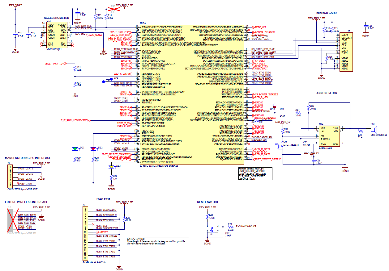
  • No the 3.3V rail stays around 2.0V.  Attached is the IO piece of the schematic, does that help?

    Thanks,

    Amanda

  • Hello Amanda,

    Regarding the accelerometer, when you connected the 3.3V 0Ohm resistor, did you disconnect the VBAT trace to the Accelerometer?

    What about the power supply stages. Are, there any other power supply still active other than the VBAT coin cell?

    Regards
    Amit
  • Actually the rework for the accelerometer only involved connecting R13 and R14 to 3.3V (that 0 ohm jumper was not used). The accelerometer needs to be powered by the coin cell because it causes the trigger for the WAKE pin but it should only consume around 100uA.

    All of the other power regulators (LED_PWR_5V) are disabled before going into hibernation mode and the 3.3V regulator is disabled with the HIB signal.

    Thanks,
    Amanda
  • Hello Amanda

    And you have made sure that the remaining supplies are 0V when powered down?

    Can you please share the remaining connection of the TM4C129x device?

    I am suspecting that there is another path by which the current is being sinked into the 3.3V supply?

    Regards
    Amit
  • I have confirmed that the LED_PWR_5V rail (seen in the previous schematic) is also powered down, ENABLE pin = 0V.

    One interesting thing that I notice is when I connect a PC to J8 which is UART signals brought to a header, the current draw from VBat goes from 4788uA to 1719uA.  The UART TX signal is being held high (or at the 1.8V of the 3.3V rail).  Are there additional firmware steps that need to be taken to disable peripherals prior to going into hibernation?

    Below is the remaining power connections to the uC.

  • This issue has been resolved with both a firmware and hardware change. The firmware issue was caused by the VDD3ON mode being enabled in the hibernate module of the TivaWare driver library because the HIBERNATE_WAKE_PIN and HIBERNATE_WAKE_GPIO are the same but you only need to enable the VDD3ON mode if using the GPIO or RESET pins as the wake sources.

    The hardware issue was indeed another GPIO being pulled high to VBAT and essentially powering the uC through that signal.

    Thanks for the help,
    Amanda