This thread has been locked.

If you have a related question, please click the "Ask a related question" button in the top right corner. The newly created question will be automatically linked to this question.

Dead band example negates clearing cycle & PWM generator outputs are coupled?

Guru 55913 points
Other Parts Discussed in Thread: TM4C1294NCPDT, LM3S8971

Seems as if the example program (deadband.c) inserts delay asserting a single dead band generator (DBG) and fails to produce same results when 2 or more DBG and periods are configured.

Invoking DBG delay without quickly clearing DB delay each cycle Fails if synchronous updates are enabled?

TM4C1294NCPDTi3 data sheet fails to mention the PWM generator outputs are coupled as programmer believes they are, check below text. Might that be giving others a false reality of phase pair co-partner 1/2 bridge signals? Seems perpetual enabled DBG's (per example) actually produce useless bridge wave forms. There seems to be a Full DB mode 6 and a partially enabled DB mode since PWMbnDBFALL asserts even after PWMnDBCTRL bit has been cleared.

Started to do a rewrite (deadband.c) for EK-TM4C294; Discovered DBG's are not being cleared after each pin write cycle and (Gen_Mode_NoSync) has been enabled.

  • Ending your (often) declarative sentences with a question mark is NOT conventional usage.  

    Such will confuse your readers - and (may) signal that your writing's intent has "changed" midstream.

    Two quick illustrations: (from your work, above)

    "Reply to Dead band example negates clearing cycle & PWM generator outputs are coupled?"

    and

    "Invoking DBG delay without quickly clearing DB delay each cycle (3 phase commutation) Fails if Synchronous updates are enabled?"

    Both sentences (appear) to be strong assertions - the (ending) question marks simply confound!   That's NOT good!

    Violating normal/customary English usage - if that's your intent - does NOT strengthen your proposition.   And your "misuse" is occurring w/greater frequency - bad habits prove difficult to break...

    The issue you report demands great "Attention to Detail" - such should be reflected (modeled) in your written plea for assistance - here...

  • Perhaps you should spend more time studying the issue instead of finding fault in questioning the motive as valid skepticism. The programmer did make very strong baseless and unfounded assertions that have no datasheet supporting facts to back them up.
  • Others/myself (might) study your issues if the (question) was properly framed/presented.    You have noted the dearth of responders - and their ongoing requests for clarity (i.e. vendor Chuck's recent posts) for example.   Might (proper) sentence structure lead to improved response?

    Long, unclear, multi-subject sentences - ending w/a question mark (as last ditch - after-thought) - may not best serve your interests.

  • I need to second you here.
    I avoid getting in a discussion with someone who does not (or cannot) express his problem in a clear, understandable way.
    It is the (original) poster's obligation to frame his issue in a comprehensible and interesting manner, to attract the attention of (volunteering) engineers.
  • Again: where TM4C1294NCPDT data sheet section 23.3.5 is programmers point made clear (coupling generator output pwmA to pwmB ) and that synchronous update obviously negates dead band?

    Per 23.3.5 (dead band generator) PWM outputs are not coupled during dead band. Section 23.3.5 states generator output pwmB is dropped and generator pwmA inverted to form pwmB.

    Single generator dead band project works great but falls apart adding a second generator into the project. Two generator project with synchronous pwm updates and dead band enabled/clearing or not falls apart and truncates pwmB pulse width as pwmA remains constant low. Test it your self, surely you have an EK-TM4C1294-XL launch pad at the ready.

    1GeneratorDeadBandProject.zip

    2GeneratorDeadBandProject.zip

  • This issue goes above typical engineers comprehension since the datasheet obviously leaves out and misconstrues important details regarding dead band delay function.

    Past time for TI big guns to have a look at why 3 phase commutation is being inflicted with dead band truncation pwmB. The alternative would be to properly detail section 23.3.5 provided below as programmer text relates (TM4C123) his dead band project and PWM peripheral may not behave the same as TM4C1294.

    The pass through dead band is the highly important point in 3 phase commutation as leaving it perpetually enabled creates a bazar looking dis-functional co-phase pair signals. Disabling dead band generator, pwmB delay (PWMnDBFALL) register value remains active LM3S8971 & TM4C1294. The register delay period (PWMnDBFALL) should not be present in PWM generator pwmB output if or when dead band is disabled. 

  • BP101 said:
    Again: where (w/in) TM4C1294NCPDT data sheet section 23.3.5 is programmers point made clear (coupling generator output pwmA to pwmB ) and that synchronous update obviously negates dead band?

    Suspect poster f.m. agrees that your use of "Again" is gratuitous here.   (your past posts border upon incomprehensible - due to multiple language violations.)  

    Now here, your use of, "Where" (as past prompted) DOES signal your sentence as interrogatory - yet you cannot let your question, "Stand on its own!"   Instead - as we've (so often/always) come to note w/in BP/Brett post - you feel COMPELLED to "Force your viewpoint!"   (i.e. "update obviously negates dead band")

    That's off-putting - is it not?   Are you asking a question of the forum - or - as many believe - cramming (your) beliefs "Down forum throats!"   That's sub-optimal - and surely has resulted in the dearth of responses to your postings.

    Attacking those who have the "guts" to "identify this (undesired) tendency" further identifies posters as, "NOT REALLY" being interested in the views/suggestions of others.

  • That's off-putting - is it not?   Are you asking a question of the forum - or - as many believe - cramming (your) beliefs "Down forum throats!"   That's sub-optimal - and surely has resulted in the dearth of responses to your postings.

    Attacking those who have the "guts" to "identify this (undesired) tendency" further identifies posters in "NOT REALLY" being interested in the views/suggestions of others. 

    I'm quite confident that <this> issue will resolve itself over time ...

  • Not only f.m.

    BP. slow down, be clear. Show simple examples not long zips. Provide evidence of the odd behaviour.

    You may find that the obvious is more subtle than you first thought.

    Robert
  • Have a look again the project programmers note 1st thread posted, contradicts data sheet. Seems you expect poster to think for you even when poster has provided plausible scenarios for odd peripheral behavior and later evidence.

    You actually have to have some basic understanding of how dead band generators work (TM4C1294NCPDT data sheet) to know his statement is unfounded.
  • Re: quite confident...
    Not a chance without flaw being (first) identified - exposing the (likely) negative effects - and appealing for (some) modification.
  • I didn't mean that technical issue, though ...
  • You have to load the sample programs (modify to your taste) to find dead band don't work the same when 2 or even 3 PWM generators are configured.

    That is 2 or 3 phase commutation dead band cycle then requires special handling the example single generator dead band program does not relate.

    As Robert asked in an alternate thread, what is the reason to enable(Set) and disable (Clear) dead band in PWM pins state changes. Robert raises a very good head scratching question that may have an answer that DBG output delay pwmB delay time is not being blended with the period of pwmA as it should be. What goes into pwmA must come out pwmB however delayed by PWMnDBFALL register bits setting.

    That is by the book, dead band section 23.3.5 and iterated many time by this poster that is not happen on any level when multiple DBG's are configured for global synchronous updates past or present silicon LM3S or TM4C.  Might it be a SW related anomaly being described, not so much the procedure rather the method of the procedure as it relate to the silicon and how DGB receive the very first update from PWM generators when it is being configured.

  • Your not focusing on several key points made in the opening paragraphs and instead desire to sail off in other directions away from the issue.

    Constant battering of the posters issue will not render any answers for why example dead band project and programmer notes contradicts data sheet text. Absolute data sheet details are Necessary to write SW that actually works as it was indented and oh how badly some have stumbled along the way past and present. That is according to the only source available we have to trouble shoot HW is held to facts presented in the half witted data sheet information being provided to vendors.
  • BP101 said:
    Constant battering of the posters issue

    As usual - your argument proves so weak - that you (must) resort to gross exaggeration.     "Constant" - really - hardly!

    There are now FOUR here (1 vendor) who registered objection to your clarity, grammar & basic sentence structure.

    Robert & I have (long) requested basic scope caps of the output of a single PWM Generator.   (as that's all you can provide w/your simple, 2 channel scope)   Such will insure that the single channel does properly respond to your dead-band code's desire.   Asking those here to (blindly) accept "your viewpoint" - minus (even) vendor requested scope-caps/illustration - proves NOT especially compelling...

  • Use past code it's clearer.

    Still needs a capture of the offending behaviour to document what's going on, your prose is less than clear on this point.

    However something caught my eye

    BP101 said:
    // Clear dead band after any high side pin drive asserts

    I don't know if this is your code or TI's (again in need of more clarity) but why on earth would you disable deadband while running? That defeats the purpose.

    Robert

  • The problem was the pwmB register truncates the minimum pulse width on pass through duty cycle updates because it is always enabled even when it is asserted disable. That was causing some major issues on the low side MOSFETS having even symmetry with properly working pwmA register changes. I believe we are not being told the entire schema (data sheet) of DBG and how they update during PWM pass through events in global synchronous DBG and local update modes.

    Alternate thread posted answer PWMnDBCTRL enable bit seemingly is RW1C must be toggled to effect the register value change. That likely is the same for enabling DBG and have added the very same ENABLE bit toggles on that bit as well.

    You what they say - jiggle it a BIT and it might start working.
  • Seem to me objections were waved time again without probable cause after having provided detailed explanation in 1000 words or less. This is a learning event for you as well my friend, we all need to put down the swords and get down to the nitty gritty.

    The other thread pick bottom trace single 120ns pulse indicates DBG pwmB delay was not blending into the minimum pulse width. That DBG pulse should not be present by it's lonesome without the very same pwmA pulse width payload shown in the (top trace). Having disregard for the (posted) datasheet theory of operations overview does not go well for your argument. Instead you and others choose to nit pick on things that didn't quite match the symptoms of issue being described and illustrated.

    Be brave watch the video, pause freeze frame reveals bottom trace that very same single improper 120ns DBG pulse is present without any pulse width  payload. If pwmB signal originates from pwmA it must appear much like pwmA or something ain't working right in my book. Then try to dual DGB timers zip provided here and your entire  belief of what you thought you knew to be true will be blasted right out of the water. Be sure to hang a test probe on the 2nd generators pwmB  pin and one on the first gens pwmB pin and be completely baffled.

    That skepticism curiosity  paid off cause it twernt working even a BIT properly, check it for yourself.

    5327.2GeneratorDeadBandProject.zip

  • You are not paying attention to any of the objections, no matter how vigorously waved.

    Robert
  • You have to actually load the SW example dual generator BIN firmware from ZIP file debug folder to your TM4C129x. Order to understand the objective DBG function only works in single DBG mode. And according to the info in datasheet (PWM_GEN_MODE_SYNC) should not have an effect of DBG when global sync updates of the period are common place in 3 phase PWM commutation. That of course infers we are configuring generators with (PWM_GEN_MODE_GEN_SYNC_GLOBAL | PWM_GEN_MODE_DB_SYNC_GLOBAL). At that point what difference does it make to PWM generation DBG's if one or 100 generators are chained to synchronous global updates.

    It should not be a problem for multiple DBG concurrently producing PWM signals with added delay periods. The dual generator example ZIP proves the delayed edges of 2 DGB are bazar, show up across 2 separate generators and are not even the set pulse width periods that worked for a single generator. What occurs is a single pulse unrelated to the period delayed 100ns between 2 DBG (PF3/PG1) and no other PWM pulses (PF1/PG0) remain high or low if inverted outputs are enabled on the control block. If the PWMCLK is set 60mHz 80us periods -- DBG's create the very same delayed 100ns pulses even configuring the PWMCLK 15mHz.

    That suggests something is not working as intended for what ever the reason. BTW the PWMCLK of TM4C123 uses a different function call than TM4C129x and was noted so in the 2 generator ZIP.
  • BTW: Our motor will not run nor even start with dead band set and proper DBG clearing.

    Have discovered  DGB delays registers are not actually disabled unless we write 0x0000.0000 to PWMnDBRISE/FALL during the clear (disable) process. Otherwise when clear the delay set in PWMnDBRIS/FALL is still asserted. That behavior is noted both LM3S and TM4C PWM peripherals.

    The reason obvious on scope is the low side pwmB is inverted pwmA creates longer active high FET on times yet pwmA remains at roughly 15-32us on times. That scenario reveres when DBG's registers are cleared (0x0000.0000) the high side on times drop to the minimum pulse width setting 1.2us and low side are roughly 15-32us. Cleared DBG's (0x0000.0000) and Increasing pwmA  pulse width has a reverse effect of directly reducing pwmB -- (a no win scenario). The low side inversion pwmB seemingly provides current stability in the motor phases especially during the first few electrical angles during rotor start.  

    Dead band clear function in Stellaris Tiva ware are not stopping the propagation of delayed edges when the DBG's are set disabled in PWMnDBCTRL registers. Primary reason for so much confusion (myself) trusting DBG clear function. Thinking dead band was disabled via SW yet the delay edges still remain active in the PWM signal generation when (DBG pass through mode) should have been re-established. That seemingly has fooled many along the way.  

  • Why would you remove your deadband protection? I've not seen a situation where you would change it once set nevermind remove it.

    Robert
  • Because that is considered pass through PWM mode when pwmA/pwmB registers RED/FED are (0x0000.0000) and not occurring in Tivaware TM4C or LM3S by simply disabling the PWMnDBCTL ENABLE bit.

    What occurs is pwmB improperly Inverts the output after calling function PWMClearDeadBand(). That function name an Oxymoron if ever one existed as it don't restore PWM dead band Pass through mode. The innocent programmer gets bamboozled goes along with the ploy creating Doxygen source statements that do not relate to the condition being asserted on PWMClearBand(). What that does is change the polarity of pwmB after the PWMnCTRL ENABLE bit is set during invoking the PWMSetDeadBand().

    The short is we don't clear dead band during commutation. Logically how is dead band protection being asserted if it was last cleared in SW flow prior to commutation. Clearing dead band in Stellaris/Tivaware actually asserts and inverts pwmB from previously configuring dead band default (pass through) mode set in PWMSetDeadBand(). That action actually sets dead band protection not clears dead band as the function is named.

    And pwmB is randomly triggering a single pulses on the rising edge of pwmA captured in real time events. It would seem logical we should never be able to capture a single RED/FED pulse without the set pulse width added. DBG is illustrated and stated to delay the output edge not reproduce it as a single one shot delay pulse at he end of the generator period.
  • That didn't answer my question.

    Robert
  • Consider the FED delay assertions is only necessary during FET gate turn off events (falling edge) in this posted case DBG improperly appends FED delay time into the PWM period end. The DBG inverted pwmB is supposed to append the delay to the period equal to the duty cycle of pwmA since pwmB is simply inverted and delayed pass through of pwmA.

    Three phase motor commutation gates the active free running PWM generators pin states at the randomly adjusted duty cycle in six 60 degree frames. The FET gate turn off events occur immediately following a pin state change event in each 60 degree frame which there are 6 code change events 1 every 60 degrees. Rotor position determines the next sensorless commutation trigger event further complicating 60 degree frame timing schema.

    That pwmA period shown first post captured top trace 120ns RED + the pulse width equals roughly 1212ns versus bottom trace showing 120ns FED appended to the very end of the period with no pulse width.

    Seems as if the DBG 10bit counter has truncated the pulse width pwmB . I suspected truncation might be due to When rather than How the pin state was being modulated. Perhaps a reason TM4C has the ability to synchronize DGB via PWM_GEN_MODE_DB_SYNC_GLOBAL where the LM3S did not. Even that newer PWM generator register configuration does not stop this anomaly from occurring on the TM4C so it seems something else is causing truncation of pwmB pulse width.
  • You seem to have lost track of my question. Why would you disable the deadband once running?

    Robert
  • Tried to answer your question several times but you seem adamant to the reasons given. The point is your right and I agree but that would insinuate the dead band 10 bit counter is functioning correctly or in a desirable manor. My idea to clear DBG after pin state changes did not actually disable DBG, instead clearing actually drops and inverts the pwmB output and sets pwmA in pass through mode but FED truncates the pwmA pulse width. Fairly sure it is dropping PWM0 pwmB as asserting later pulse width changes explicitly to low side pins are lost. The oddest part is pass through mode 0 is not achieved by simply disabling PWMnDBCTRL ENABLE bit. We have to update the PWMnDBRISE/FALL register with 0x0000.0000 and toggle the ENABLE bit true leaving it false to set pass through  mode 0. That may be due to how PWM0 passes the binary register configuration into the DBG 10 bit counters. 

    The DBG clear function clears PWNnDBCTRL ENABLE bit yet dead band PWMnDBGFALL/RISE registers are still asserting, how can that be if ENABLE is clear?

    It would seem DBG mode 0 or 6 is not behaving as described. The note below adds very little to the argument Tivaware is behaving correctly.

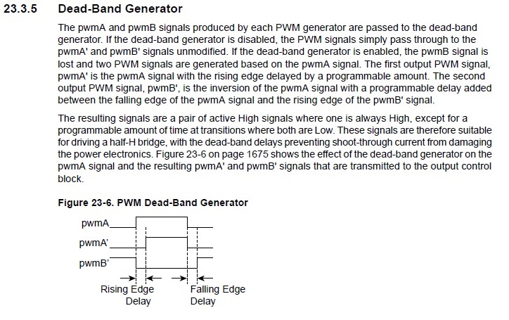
    The resulting signals are a pair of active High signals where one is always High, except for a programmable amount of time at transitions where both are Low.

    That statement to me infers pwmB 10 bit counter FED is blended into pwmA pulse width not simply inserted at the end of the 80us pulse width period like it is doing. That symptom seems to cause an uneven symmetry in PWM low side that differs greatly from that of the high side. 

  • Your logic appears to have become a touch circular. The asserted misbehavior of deadband disable while running proves the previously asserted misbehavior of the deadband for which you disabled deadband while running as an attempted workaround. A fine tower of assertions built on a foundation of missing measurements.

    That highlighted section is a pretty good description of how deadband is supposed to work.

    Robert
  • Again the capture below shows pwmA pulse width 1.2us to 1.4us is roughly 10 times pwmB 120ns.  Both are low and isn't that odd a 10 bit counter and pwmB pulse width is typically 10 times shorter than pwmA pulse width in the same delay period. Review F280 Enhanced PWM datasheet gives clarity to how PWM0 drops CMPB in the dead band timing diagram. It helps if we know how DBG should work to then understand that it seemingly isn't working as intended or described. The low side FET temperature rise well above high side is a good indication Sherlock Holmes would not so easily dismiss as antidotal behavior. How could anyone simply ignore that odd behavior as simply being an anomaly. 

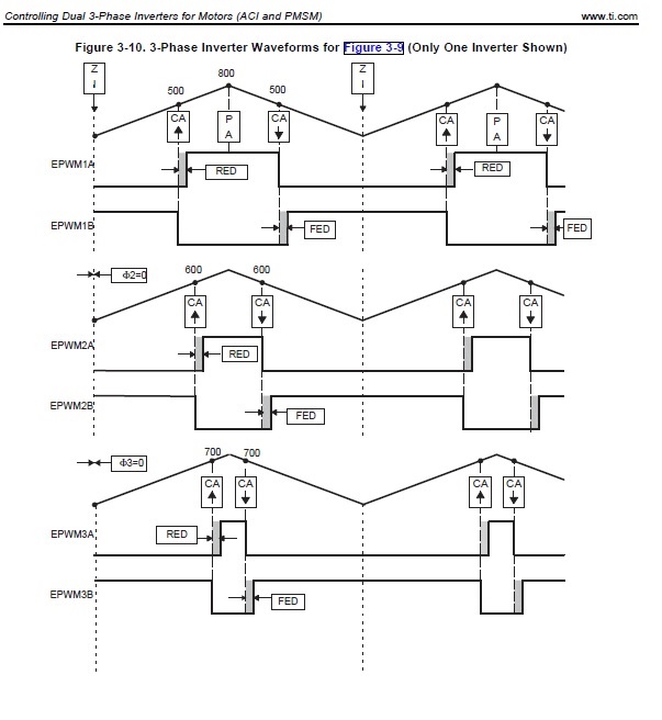
    Notice the 3 phases all have staggered pulse widths. Seems a odd idea unless done some kind of round robin circular giving each phase pair equal on time. Then bridge FETS temperatures might run more balanced. The idea this illustration shows CMPB-U/D match events are not present in the dead band. That might give a clue to what is going on with DBG's in TM4C1294 which give no timing diagrams that match the actual programmed behavior. The problem TM4C/LM3S and FED is not always part of the pulse width derived from pwmA (shown in this illustration) and instead is a rogue 10 bit counter firing event appended to each period end that only includes the derived pwmA pulse once per 3.8ms PWM update cycle. The 3.8ms is relative to rotor speed duty cycle and faster speeds produce shorter full periods in switched commutation.


  • Difficult to comprehend pwmB 10 bit counter seems to inject pulses at the end of all (remaining) 80us periods accept the very 1st 80us period. Each 3.8ms cycle FED appears as a one shot event of an 80us period 12.5kHz accept for full dead delay period 240us they line up real time but impossible to capture acquisition time into scope memory. Dead band does protect each 1/2 bridge from shoot through but produces uneven symmetry pwmA to pwmB and very different from timing illustrated above post figure 3-10.

  • That diagram is exactly what is to be expected from deadband. Nothing odd about it. Certainly no indication of anything round robin.

    You've yet to explain what signals those scope traces are.

    Robert
  • The diagram above is showing (properly operating) dead band generators timing F280x ePWM. That does not infer the TM4C/LM3S dead band generators are or were ever operating correctly in the first place. And or some kind of SW anomaly could be setting a cascade failure into motion.

    The scope capture above proves dead band pwmB output is producing single FED delay periods from the input signal pwmA inverted and delayed (minus any pulse width) shown in the timing diagram. That indicates the 10 bit counter (pwmB DBG) is adding delay periods at the wrong place relative to the pulse width of pwmA. That does not indicate a strict period is derived from pwmA and pwmB delay is somehow being append to every other generator period after and only after the initial RED pulse width changes of edge position. It also seems as if the output signals pwmA and pwmB are loosing center aligned positioning show statically centered in the diagram when the pulse width is being stripped from pwmB output.

    Could it be PWM0 pwmB input is decoupling from pwmA and triggering the 10 bit DBG counter directly from PWM0 generator at those intervals. That might explain how the succeeding 80us periods then have 120ns FED delay appended in place of the pulse width changes shown occurring in pwmA.

    Typically in motor commutation engineers don't maintain staggered PWM generator periods as depicted in the diagram. Reason for mentioning such pattern would not be proper unless in some kind rotation. The programming example (ePWM) simply states initial generator periods. May give period staggering a try latter as the duty cycle will quickly adjust all 3 in the waveform update call relative to phase current demand. Staggering periods could perhaps improve motor rotation in one direction during the initial startup cycle. There must have been some reason for staggering not mentioned in the programming example.


  • TM4C data sheet section 23.3.5:

    If the dead-band generator is enabled, the pwmB signal is lost and two PWM signals are generated based on the pwmA signal.

    The SW anomaly:

    If PWM0 generator pulse width is set when dead band is enabled, PWM1 or pwmB input is not lost. The PWM1 pwmB dead band generator input passes through and the dead band generator 10 bit counter appends PWMnDBFED register contents to the period end. That creates uneven unbalanced inefficient FET on periods in the 1/2 bridge being one FET stays on longer than the other. 

    That is to say PWMnDBCTRL ENABLE bit has no control stopping PWM1 pwmB periods being injected into the dead band generator passing right on through as if DBG mode 0 is enabled when mode 6 is enabled and asserting. If that was not true when the DBG is thus cleared the PWM signal should invert back to normal polarity.

    Have discovered and past suggested writing 0x0000.0000 to PWMnDBFALL/RISE and disabling PWMnDBCTRL is the only way to decouple PWM0/1 dead band generator pwmA/B. When PWM0/1 are decoupled from DBG they both pass through non-inverted as complementary pair of center aligned PWM signals