


Other Parts Discussed in Thread: TM4C129XNCZAD
hello there, this walter kim. I have a serious problem with ov7670
I'm currently using tm4c129xnczad board and ov7670 module with al422b fifo
i have printed out my RGB value on LCD which i got from ov7670 in bayer pattern
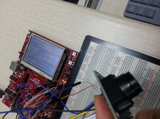
however, the outcome of the image has problem.
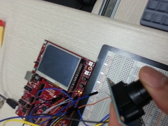
good thing is that it recognizes when camera is blocked, the LCD turns to black.
below is my source code, please revise and give some comments if you could.
I appreciate your help thank you very much.
walter
#include <stdint.h>
#include <stdbool.h>
#include "grlib/grlib.h"
#include "driverlib/sysctl.h"
#include "driverlib/gpio.h"
#include "driverlib/systick.h"
#include "driverlib/timer.h"
#include "driverlib/interrupt.h"
#include "driverlib/pin_map.h"
#include "driverlib/uart.h"
#include "driverlib/i2c.h"
#include "driverlib/rom.h"
#include "inc/hw_nvic.h"
#include "inc/hw_memmap.h"
#include "inc/hw_types.h"
#include "inc/hw_ints.h"
#include "utils/uartstdio.h"
#include "drivers/kentec320x240x16_ssd2119.h"
#include "drivers/pinout.h"
#define IMAGESIZE 76800
void wait_ms(uint32_t count);
void wait_us(uint32_t count);
void write_reg(uint32_t addr, uint32_t data);
uint32_t read_reg(uint32_t addr);
void init_QVGA();
uint32_t read_byte();
uint32_t sysClkFreq;
uint8_t input_array[IMAGESIZE];
int main(void)
{
uint32_t i, j, RGB_value;
tContext sContext;
// set system clock
sysClkFreq = SysCtlClockFreqSet((SYSCTL_XTAL_25MHZ | SYSCTL_OSC_MAIN | SYSCTL_USE_PLL | SYSCTL_CFG_VCO_480), 120000000);
// Enable Peripheral for I2C
SysCtlPeripheralEnable(SYSCTL_PERIPH_I2C2);
SysCtlPeripheralEnable(SYSCTL_PERIPH_GPIOL);
// Enable Port G & K
SysCtlPeripheralEnable(SYSCTL_PERIPH_GPIOG);
SysCtlPeripheralEnable(SYSCTL_PERIPH_GPIOK);
// configure UART
UARTStdioConfig(0, 57600, sysClkFreq);
// enable Port A for UART
SysCtlPeripheralEnable(SYSCTL_PERIPH_GPIOA);
// configure PA0, PA1 to UART
GPIOPinConfigure(GPIO_PA0_U0RX);
GPIOPinConfigure(GPIO_PA1_U0TX);
GPIOPinTypeUART(GPIO_PORTA_BASE, GPIO_PIN_0 | GPIO_PIN_1);
// configure I2C
I2CMasterInitExpClk(I2C2_BASE, sysClkFreq, true);
// Configure pin PL0 as I2C2 SDA
GPIOPinConfigure(GPIO_PL0_I2C2SDA);
GPIOPinTypeI2C(GPIO_PORTL_BASE, GPIO_PIN_0);
// Configure pin PL1 as I2C2 SCL
GPIOPinConfigure(GPIO_PL1_I2C2SCL);
GPIOPinTypeI2CSCL(GPIO_PORTL_BASE, GPIO_PIN_1);
// PL2(VSYNC) PL3(RCK)
GPIOPinTypeGPIOInput(GPIO_PORTL_BASE, GPIO_PIN_2);
GPIOPinTypeGPIOOutput(GPIO_PORTL_BASE, GPIO_PIN_3);
// VSYNC interrupt
GPIOIntTypeSet(GPIO_PORTL_BASE, GPIO_PIN_2, GPIO_RISING_EDGE);
GPIOIntClear(GPIO_PORTL_BASE, GPIO_PIN_2);
// Configure for DO0 - DO7
GPIOPinTypeGPIOInput(GPIO_PORTG_BASE, GPIO_PIN_0);
GPIOPinTypeGPIOInput(GPIO_PORTG_BASE, GPIO_PIN_1);
GPIOPinTypeGPIOInput(GPIO_PORTG_BASE, GPIO_PIN_2);
GPIOPinTypeGPIOInput(GPIO_PORTG_BASE, GPIO_PIN_3);
GPIOPinTypeGPIOInput(GPIO_PORTG_BASE, GPIO_PIN_4);
GPIOPinTypeGPIOInput(GPIO_PORTG_BASE, GPIO_PIN_5);
GPIOPinTypeGPIOInput(GPIO_PORTG_BASE, GPIO_PIN_6);
GPIOPinTypeGPIOInput(GPIO_PORTG_BASE, GPIO_PIN_7);
// PK0(OE) PK1(RRST)
GPIOPinTypeGPIOOutput(GPIO_PORTK_BASE, GPIO_PIN_0);
GPIOPinTypeGPIOOutput(GPIO_PORTK_BASE, GPIO_PIN_1);
// PK2(WR) PK3(WRST) PL4(RST)
GPIOPinTypeGPIOOutput(GPIO_PORTK_BASE, GPIO_PIN_2);
GPIOPinTypeGPIOOutput(GPIO_PORTK_BASE, GPIO_PIN_3);
GPIOPinTypeGPIOOutput(GPIO_PORTL_BASE, GPIO_PIN_4);
// reset camera
GPIOPinWrite(GPIO_PORTL_BASE, GPIO_PIN_4, 0x01 << 4); // RST = 1;
wait_ms(200);
GPIOPinWrite(GPIO_PORTL_BASE, GPIO_PIN_4, 0x00); // RST = 0;
wait_ms(200);
GPIOPinWrite(GPIO_PORTL_BASE, GPIO_PIN_4, 0x01 << 4); // RST = 1;
wait_ms(200);
GPIOPinWrite(GPIO_PORTL_BASE, GPIO_PIN_3, 0x01 << 3); // RCK = 1
GPIOPinWrite(GPIO_PORTK_BASE, GPIO_PIN_0, 0x00); // OE = 0
GPIOPinWrite(GPIO_PORTK_BASE, GPIO_PIN_1, 0x01 << 1); // RRST = 1
GPIOPinWrite(GPIO_PORTK_BASE, GPIO_PIN_2, 0x00); // WR = 0
GPIOPinWrite(GPIO_PORTK_BASE, GPIO_PIN_3, 0x01 << 3); // WRST = 1
// camera initialize
init_QVGA();
wait_ms(200);
PinoutSet();
// Initialize the display driver.
Kentec320x240x16_SSD2119Init(sysClkFreq);
// Initialize the graphics context.
GrContextInit(&sContext, &g_sKentec320x240x16_SSD2119);
while(1)
{
// reset write address
GPIOPinWrite(GPIO_PORTK_BASE, GPIO_PIN_3, 0x00); // WRST = 0
wait_us(1);
GPIOPinWrite(GPIO_PORTL_BASE, GPIO_PIN_3, 0x00); // RCK = 0
wait_us(1);
GPIOPinWrite(GPIO_PORTL_BASE, GPIO_PIN_3, 0x01 << 3); // RCK = 1
wait_us(1);
GPIOPinWrite(GPIO_PORTL_BASE, GPIO_PIN_3, 0x00); // RCK = 0
wait_us(1);
GPIOPinWrite(GPIO_PORTL_BASE, GPIO_PIN_3, 0x01 << 3); // RCK = 1
GPIOPinWrite(GPIO_PORTK_BASE, GPIO_PIN_3, 0x01 << 3); // WRST = 1
// check rising edge of VSYNC
while(1)
{
if((GPIOIntStatus(GPIO_PORTL_BASE, false) & 0x01 << 2) == 0x01 << 2)
{
GPIOPinWrite(GPIO_PORTK_BASE, GPIO_PIN_2, 0x01 << 2); // WR = 1
GPIOIntClear(GPIO_PORTL_BASE, GPIO_PIN_2); // VSYNC interrupt clear
break;
}
}
while(1)
{
if((GPIOIntStatus(GPIO_PORTL_BASE, false) & 0x01 << 2) == 0x01 << 2)
{
GPIOPinWrite(GPIO_PORTK_BASE, GPIO_PIN_2, 0x00); // WR = 0
GPIOIntClear(GPIO_PORTL_BASE, GPIO_PIN_2); // VSYNC interrupt clear
break;
}
}
// read start
GPIOPinWrite(GPIO_PORTK_BASE, GPIO_PIN_1, 0x00); // RRST = 0
wait_us(1);
GPIOPinWrite(GPIO_PORTL_BASE, GPIO_PIN_3, 0x00); // RCK = 0
wait_us(1);
GPIOPinWrite(GPIO_PORTL_BASE, GPIO_PIN_3, 0x01 << 3); // RCK = 1
wait_us(1);
GPIOPinWrite(GPIO_PORTL_BASE, GPIO_PIN_3, 0x00); // RCK = 0
wait_us(1);
GPIOPinWrite(GPIO_PORTL_BASE, GPIO_PIN_3, 0x01 << 3); // RCK = 1
wait_us(1);
GPIOPinWrite(GPIO_PORTK_BASE, GPIO_PIN_1, 0x01 << 1); // RRST = 1
wait_us(1);
GPIOPinWrite(GPIO_PORTL_BASE, GPIO_PIN_3, 0x00); // RCK = 0
for(i = 0; i < IMAGESIZE; i++)
{
input_array[i] = read_byte();
}
for(j = 0; j < 240; j = j + 2)
{
for(i = 0; i < 320; i = i + 2)
{
// input_array[i + j * 320]; G value
// input_array[(i + 1) + j * 320]; R value
// input_array[i + (j + 1) * 320]; B value
// input_array[(i + 1) + (j + 1) * 320]; G value
RGB_value = input_array[(i + 1) + j * 320];
RGB_value = RGB_value << 8 | input_array[i + j * 320];
RGB_value = RGB_value << 8 | input_array[i + (j + 1) * 320];
GrContextForegroundSet(&sContext, RGB_value);
GrLineDrawV(&sContext, i, j, j);
RGB_value = input_array[(i + 1) + j * 320];
RGB_value = RGB_value << 8 | input_array[i + j * 320];
RGB_value = RGB_value << 8 | input_array[i + (j + 1) * 320];
GrContextForegroundSet(&sContext, RGB_value);
GrLineDrawV(&sContext, i + 1, j, j);
RGB_value = input_array[(i + 1) + j * 320];
RGB_value = RGB_value << 8 | input_array[(i + 1) + (j + 1) * 320];
RGB_value = RGB_value << 8 | input_array[i + (j + 1) * 320];
GrContextForegroundSet(&sContext, RGB_value);
GrLineDrawV(&sContext, i, j + 1, j + 1);
RGB_value = input_array[(i + 1) + j * 320];
RGB_value = RGB_value << 8 | input_array[(i + 1) + (j + 1) * 320];
RGB_value = RGB_value << 8 | input_array[i + (j + 1) * 320];
GrContextForegroundSet(&sContext, RGB_value);
GrLineDrawV(&sContext, i + 1, j + 1, j + 1);
}
}
GrFlush(&sContext);
SysCtlDelay(sysClkFreq / 3);
//GPIOPinWrite(GPIO_PORTL_BASE, GPIO_PIN_3, 0x01 << 3); // RCK = 1
}
}
void write_reg(uint32_t addr, uint32_t data)
{
I2CMasterSlaveAddrSet(I2C2_BASE, 0x21, false);
I2CMasterDataPut(I2C2_BASE, addr);
I2CMasterControl(I2C2_BASE, I2C_MASTER_CMD_BURST_SEND_START);
while(!(I2CMasterIntStatusEx(I2C2_BASE, false) & 0x01));
I2CMasterIntClear(I2C2_BASE);
I2CMasterDataPut(I2C2_BASE, data);
I2CMasterControl(I2C2_BASE, I2C_MASTER_CMD_BURST_SEND_FINISH);
while(!(I2CMasterIntStatusEx(I2C2_BASE, false) & 0x01));
I2CMasterIntClear(I2C2_BASE);
}
uint32_t read_reg(uint32_t addr)
{
I2CMasterSlaveAddrSet(I2C2_BASE, 0x21, false);
I2CMasterDataPut(I2C2_BASE, addr);
I2CMasterControl(I2C2_BASE, I2C_MASTER_CMD_SINGLE_SEND);
while(!(I2CMasterIntStatusEx(I2C2_BASE, false) & 0x01));
I2CMasterIntClear(I2C2_BASE);
I2CMasterSlaveAddrSet(I2C2_BASE, 0x21, true);
I2CMasterControl(I2C2_BASE, I2C_MASTER_CMD_SINGLE_RECEIVE);
while(!(I2CMasterIntStatusEx(I2C2_BASE, false) & 0x01));
I2CMasterIntClear(I2C2_BASE);
uint32_t data = I2CMasterDataGet(I2C2_BASE);
return data;
}
void wait_ms(uint32_t count)
{
uint32_t i;
for(i = 0; i < count; i++)
{
SysCtlDelay(sysClkFreq / 3000);
}
}
void wait_us(uint32_t count)
{
uint32_t i;
for(i = 0; i < count; i++)
{
SysCtlDelay(sysClkFreq / 3000000);
}
}
void init_QVGA()
{
write_reg(0x0C, 0x08); // REG_COM3
write_reg(0x12, 0x11); // REG_COM7
write_reg(0x3e, 0x08); // REG_COM14
//write_reg(0x40, 0x10); // REG_COM15
//write_reg(0x8C, 0x02); // RGB444
}
uint32_t read_byte()
{
uint32_t result;
GPIOPinWrite(GPIO_PORTL_BASE, GPIO_PIN_3, 0x01 << 3); // RCK = 1
result = GPIOPinRead(GPIO_PORTG_BASE, 0xFF);
wait_us(1);
GPIOPinWrite(GPIO_PORTL_BASE, GPIO_PIN_3, 0x00); // RCK = 0
wait_us(1);
return result;
}

