This thread has been locked.

If you have a related question, please click the "Ask a related question" button in the top right corner. The newly created question will be automatically linked to this question.

PWM module

Other Parts Discussed in Thread: TM4C1294NCPDT

Hello team

I am using TIVA microcontroller TM4C1294NCPDT.

I want to use PWM0 module, and I refered sample code also. I am debugging the code on Stellaris ICDI. Its working fine.

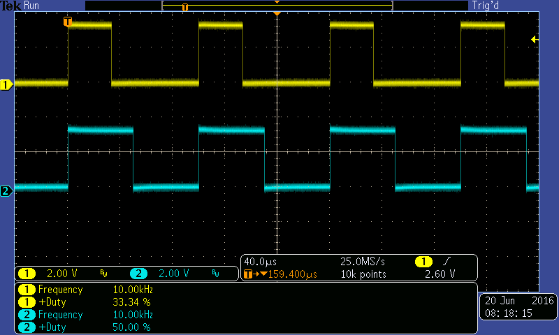
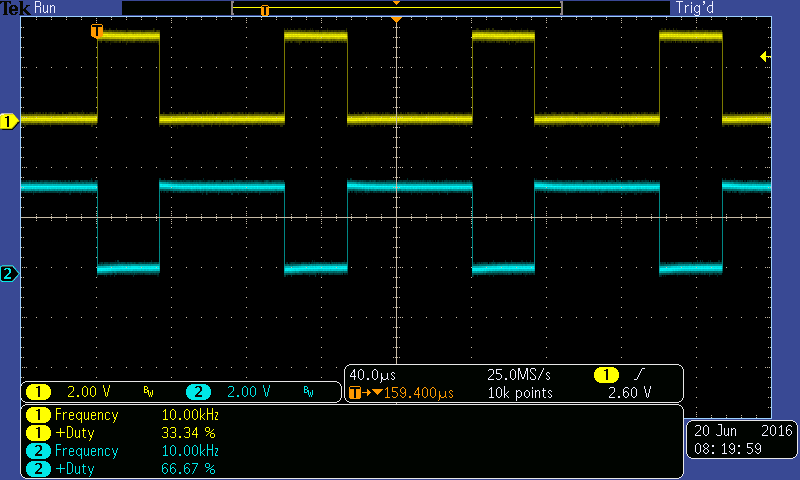
It generates PWM0 and PWM1 signals with same frequency and both signals inverted to each other. If I vary freq that applies to both signals, similarly if I vary duty cycle that applies to both signals. 

Now I need a help like that I wanted those two PWM outputs with individual freq, duty cycle settings. I have gone through Datasheet, but I am not able to configure that PWM generator for individual signals.

Please suggest me the way to generate Two independent PWM outputs of same generator. Also, if possible, provide me some example code for the same

  • Sagar Ghute said:
    generate Two independent PWM outputs of same generator.

    Really - that is your requirement.   And - in addressing that - have you noted:

    • PWMGenPeriodSet(PWM0_BASE, PWM_GEN_2, 4000);           //as an example
    • PWMPulseWidthSet(PWM0_BASE, PWM_OUT_4, 4000 / 3);    //as an example

    That "PWMGenPeriodSet()" violates your desire - does it not?   The entire PWM generator runs @ one - and only one - frequency!   Thus you cannot alter the individual frequency of the generator's 2 PWM signals - w/in the referenced PWM Generator.    You MAY alter the individual duty cycle.

    A 2nd PWM Generator may be harvested to achieve your objective.   ARM MCUs (even this vendor's) are blessed w/multiple such PWM Generators - you've provided NO justification for seeking such frequency "independence" w/in a single such generator.    (and that's always the case!)

    If you do not require "full fledged" PWM generation - you may employ an MCU Timer - placed into PWM mode - and use of two such timers will (also) achieve your desired (fully independent) PWM output "frequency and duty cycle" requirement!   (and faster/easier to achieve rather than via use of PWM Generators)

  • Hi Sagar,

    You can use the TIVAWARE API to change the PWM period and duty cycle. TM4C1294x has 4 PWM generators. Each generator has 2 comparators (A and B). Changing the value of comparator A changes the duty cycle of the pwmA signal, and changing the value of comparator B changes the
    duty cycle of the pwmB signal. If your PWM0 and PWM1 are generated from the same PWM generator, PWM0 and PWM1 will have the same period. The period is defined by PWMGenPeriodSet(). You can set different duty cycle for PWM0 and PWM1 using PWMPulseWidthSet(PWM0_BASE, PWM_OUT_0 or PWM_OUT_1, ..).

    Regards,
    QJ
  • We note that the above (vendor) post is highly derivative from earlier response - adds little of (new) value.

    Sometimes (better) to "look into the pool" before "diving in."
  • Hi Mr QJ,

    I am using following sequence for diff pulse width, but still I am getting same pulse width on both PWM signals i.e. pulse width of first signal on both signals.

    PWMPulseWidthSet(PWM0_BASE, PWM_OUT_0, PWMGenPeriodGet(PWM0_BASE, PWM_OUT_0) / 2);

    PWMPulseWidthSet(PWM0_BASE, PWM_OUT_1, PWMGenPeriodGet(PWM0_BASE, PWM_OUT_0) / 4);

  • cb1 raises pistol to head-level...(once more)
  • Hello cb1,
    Its Ok We cannot set seperate frequency to both signals, but atleast I ant seperate duty cycle for each signal. I did code as shown below. But still I am getting same duty cycle of first signal to second signal.
    Is there any way (please share code) to get same freq but different duty cycle on each signal of a PWM generator.

    PWMGenConfigure(PWM0_BASE, PWM_GEN_0, PWM_GEN_MODE_UP_DOWN | PWM_GEN_MODE_NO_SYNC);

    // Set the PWM0 period to 2000Hz,

    PWMGenPeriodSet(PWM0_BASE, PWM_GEN_0, 60000); // (1 / 2000Hz) * 120MHz = 60000 cycles.

    // Set PWM0 PD0 to a duty cycle of 25%. You set the duty cycle as a function of the period. Since the
    // period was set above, you can use the PWMGenPeriodGet()
    PWMPulseWidthSet(PWM0_BASE, PWM_OUT_0, PWMGenPeriodGet(PWM0_BASE, PWM_OUT_0) / 2);
    PWMPulseWidthSet(PWM0_BASE, PWM_OUT_1, PWMGenPeriodGet(PWM0_BASE, PWM_OUT_1) / 4);
  • My friend - find here/now PWM Generator code which has always worked (LM3S, LX4F & 4C123):

        GPIOPinTypePWM(GPIO_PORTB_BASE, GPIO_PIN_6 | GPIO_PIN_7);
    GPIOPinConfigure(GPIO_PB6_M0PWM0); GPIOPinConfigure(GPIO_PB7_M0PWM1);
    PWMGenConfigure(PWM0_BASE, PWM_GEN_0, PWM_GEN_MODE_DOWN | PWM_GEN_MODE_GEN_NO_SYNC); // Set the PWM period to 10KHz. // In this case you get: (1 / 10000Hz) * 40MHz = 4000 cycles PWMGenPeriodSet(PWM0_BASE, PWM_GEN_0, 4000); PWMPulseWidthSet(PWM0_BASE, PWM_OUT_0, 4000 / 3); // My firm prefers "hard coding" over PWMGenPeriodGet() {too risky & time consuming}
    PWMPulseWidthSet(PWM0_BASE, PWM_OUT_1,
                         4000 / 2); // independent duty cycle results!
    // Enable the PWM0 Bit 0 (PB6) and Bit 1 (PB7) output signals. // PWMOutputState(PWM0_BASE, PWM_OUT_1_BIT | PWM_OUT_0_BIT, true);
    // Enables the counter for a PWM generator block. // PWMGenEnable(PWM0_BASE, PWM_GEN_0);

    // End of code block.

    Earlier we noted your: PWMPulseWidthSet(PWM0_BASE, PWM_OUT_1, PWMGenPeriodGet(PWM0_BASE, PWM_OUT_0) / 4); // inconsistent pin ref.

    Unless I've (improperly cut/paste) above code WILL work. Splash of Green (verify) could not hurt...
  • Hello my friend cb1,

    whatever u suggested I already did it and I am getting signal on PWMout0 and PWMout1.

    Yes frequency of both signals is same.  The duty cycle of PWMout0 is 33% and duty cycle of PWMout1 is 66%. It mean PWMout1 is inverted signal of PWMout0.

    My requirement is bit different than this. I said I need to generate PWMout0 with 20% duty cycle and PWMout1 signal with 40or50% dutu cycle, means two independant dutycycles for tow diff PWM outputs of same PWM generator. Is this possible ? achievable ? is yas then suggest me code for the same.

    Thanks for your replies

    Sagar

  • Sagar Ghute said:
    The duty cycle of PWMout0 is 33% and duty cycle of PWMout1 is 66%. It mean PWMout1 is inverted signal of PWMout0.

    No, no, no my friend - it does NOT mean ANY such inversion!   Instead - the duty cycle of each PWM output is completely variable - and controllable by code.

    The fact that you are (now) able to achieve a "variation" in pulse width suggests that there is no (unwanted) short circuit between your chosen PWM output pins.

    If (and only if) you had enabled "dead-band" then (and only then) would the second PWM Output be a "true" inversion of the first PWM output.   (and the 2nd PWM output would be wider than the first - by the extent of the dead-band (if any) which you employ.

    If there's time later I'll provide a scope cap - reflecting the exact code I've supplied - to "quiet" your doubt...

  • Here now - scope caps - first illustrating (completely) independent PWM Duty Cycle and second illustrating the (intrusion) of "dead-band."


    "Normal" PWM Generator - dual channel - independent duty cycle (very much) possible.  (in play - here!)


    Here now the identical waveforms - but w/"Dead-Band" inserted.   Note (now) the signal inversion!   Kill the dead-band command to "fix."   Note that "dead-band" has been dialed to "0" (both lead & lag.)

    And here now "dead-band" w/both "lead/lag" dialed to 200 PWM clocks.   Note that duty cycle of PWM_A has "shrunk" while that of PWM_B (blue) has increased!

    This "shrinkage" of the more "active" PWM Channel (Ch_A) is not "universal" among ARM MCU vendors.   We've noted that it IS possible to maintain the duty cycle of PWM_A while fully/properly "bracketing" PWM_A w/in PWM_B.   The impact of this vendor's implementation (shrinking PWM_A) is that "FULL ON" PWM Duty will be less than (sometimes) required.   (note that most all ARM based PWM Generators are "challenged" by "severe" Duty Cycles. (those @ near 0 & near 100%)

  • its Really nice To see those Waveforms of individual PWM singals. infact thats what I wanted to achieve. But dont know what mistake is there, I am not able to get those... Here is my code n image  what I am getting by running this code

    //
    // Set the PWM clock to the system clock.
    SysCtlPWMClockSet(SYSCTL_PWMDIV_1);


    // The PWM peripheral must be enabled for use.
    SysCtlPeripheralEnable(SYSCTL_PERIPH_PWM0);

    // For this example PWM0 is used with PortF Pins 0 and 1.
    SysCtlPeripheralEnable(SYSCTL_PERIPH_GPIOF);

    GPIOPinConfigure(GPIO_PF0_M0PWM0);
    GPIOPinConfigure(GPIO_PF1_M0PWM1);

    GPIOPinTypePWM(GPIO_PORTF_BASE, GPIO_PIN_0);
    GPIOPinTypePWM(GPIO_PORTF_BASE, GPIO_PIN_1);

    //
    // Configure the PWM0 to count up/down without synchronization.
    // Note: Enabling the dead-band generator automatically couples the 2
    // outputs from the PWM block so we don't use the PWM synchronization.
    //
    PWMGenConfigure(PWM0_BASE, PWM_GEN_0, PWM_GEN_MODE_DOWN |
    PWM_GEN_MODE_GEN_NO_SYNC);


    PWMGenPeriodSet(PWM0_BASE, PWM_GEN_0, 60000); // (1 / 2000Hz) * 120MHz = 60000 cycles.

    //
    // Set PWM0 PD0 to a duty cycle of 25%.
    PWMPulseWidthSet(PWM0_BASE, PWM_OUT_0, 60000/4);
    //
    // Enable the PWM0 Bit 0 (PD0) and Bit 1 (PD1) output signals.
    //
    PWMOutputState(PWM0_BASE, PWM_OUT_1_BIT | PWM_OUT_0_BIT, true);

    // Enables the counter for a PWM generator block.

    PWMGenEnable(PWM0_BASE, PWM_GEN_0);

  • You have - quite clearly - enabled "Dead-Band" which causes the blue trace (Ch2) to respond as an inversion of yellow (Ch1)!

    I noted such in my posting - search for "deadband" w/in your code - and eliminate it to "escape" this unwanted "complementary" output.

    And - look at your code:

    PWMPulseWidthSet(PWM0_BASE, PWM_OUT_0, 60000/4);

    That's quite fine - yet that sets just ONE PWM output - not two!

    You must add:

    PWMPulseWidthSet(PWM0_BASE, PWM_OUT_1, 60000/6);   // to cause the 2nd channel to output!  ("6 is just an example)

    Again - as multiple of my posts (correctly) diagnosed - you have (likely) "Enabled Deadband" which is the cause of your LOSS of your 2nd duty cycle along with the lack of the (required) SECOND PWMPulseWidthSet().

  • Hi
    Where and how can we found out whether dead band is enabled or not..
    also did new code as u mentioned, But still I ma unable to get individual duty cycle

    New code is..

    // Set the PWM clock to the system clock.

    SysCtlPWMClockSet(SYSCTL_PWMDIV_1);

    // The PWM peripheral must be enabled for use.
    SysCtlPeripheralEnable(SYSCTL_PERIPH_PWM0);

    // PWM0 is used with PortF Pins 0 and 1.GPIO port F needs to be enabled so these pins can be used.
    SysCtlPeripheralEnable(SYSCTL_PERIPH_GPIOF);


    // Configure the GPIO pad for PWM function on pins PF0,PF1,PG0,PG1,PK4,PK5.
    GPIOPinTypePWM(GPIO_PORTF_BASE, GPIO_PIN_0);
    GPIOPinTypePWM(GPIO_PORTF_BASE, GPIO_PIN_1);


    // Configure the GPIO pin muxing to select PWM functions for these pins.
    GPIOPinConfigure(GPIO_PF0_M0PWM0);
    GPIOPinConfigure(GPIO_PF1_M0PWM1);


    // Configure the PWM0 to count up/down without synchronization.

    PWMGenConfigure(PWM0_BASE, PWM_GEN_0, PWM_GEN_MODE_DOWN | PWM_GEN_MODE_GEN_NO_SYNC);


    // Set the PWM0 period to 2000Hz,
    PWMGenPeriodSet(PWM0_BASE, PWM_GEN_0, 60000); // (1 / 2000Hz) * 120MHz = 60000 cycles.


    // Set PWM0 PD0 to a duty cycle of 25%. You set the duty cycle as a function of the period. Since the
    PWMPulseWidthSet(PWM0_BASE, PWM_OUT_0, 60000 / 4);
    PWMPulseWidthSet(PWM0_BASE, PWM_OUT_1, 60000 / 8);

    // Enable the PWM0 Bit 0 (PF0) and Bit 1 (PF1) output signals.
    PWMOutputState(PWM0_BASE, PWM_OUT_1_BIT | PWM_OUT_0_BIT, true);

    // Enables the counter for a PWM generator block.
    PWMGenEnable(PWM0_BASE, PWM_GEN_0);
  • Note that you've employed PF0 which - in the case of the TM4C123 - has been "blessed" with NMI status.   Perhaps the failure to unlock this pin is NOW causing your troubles.   If that's too hard (unlocking) - you may consider using different pins (not blessed w/NMI) for your PWM Generation.

    Your code NOW seems correct.   It is hard to imagine how the second channels "Pulse Width Set" had been neglected - earlier.

    I did provide a method to search for and identify ANY reference to "deadband" in a previous post.   You've not acknowledged - what more can I do?  (i.e. Edit > Find "deadband")

    Never have I emplaced so much effort - and still NO Verify has been awarded.   Clearly the code & method described works - scope caps prove that.