Other Parts Discussed in Thread: EK-TM4C1294XL, TM4C1294NCPDT
Hi,
I really need some help here.
I'm trying to develop a SPI communication between two peripherals in the same Launchpad (EK-TM4C1294XL). The idea is that both the Master and the Slave can send and receive information. My code until now is quite simple with only Slave sending and Master receiving.
/*
* main.c
*/
#include <stdio.h>
#include <stdbool.h>
#include <stdint.h>
#include <string.h>
#include "inc/hw_memmap.h"
#include "driverlib/gpio.h"
#include "driverlib/pin_map.h"
#include "driverlib/ssi.h"
#include "driverlib/sysctl.h"
#include "driverlib/uart.h"
#include "utils/uartstdio.h"
#include "inc/hw_ints.h"
#include "driverlib/interrupt.h"
#include "driverlib/timer.h"
#define NUM_SSI_DATA 8
uint32_t ui32SysClkFreq;
//uint32_t pui32DataTx[NUM_SSI_DATA];
//char pui32DataTx[NUM_SSI_DATA];
//char pui32DataRx[NUM_SSI_DATA];
uint8_t pui32DataTx[NUM_SSI_DATA];
uint32_t pui32DataRx[NUM_SSI_DATA];
uint32_t ui32Index = 0;
void SSI1IntHandler(void){
SSIIntClear(SSI1_BASE, SSI_RXFF);
SSIDataGet(SSI1_BASE, &pui32DataRx[ui32Index]);
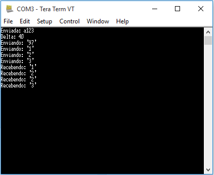
UARTprintf("Recebendo: '%u' \n", pui32DataRx[ui32Index]);
SSIDataGet(SSI1_BASE, &pui32DataRx[ui32Index+1]);
UARTprintf("Recebendo: '%u' \n", pui32DataRx[ui32Index+1]);
SSIDataGet(SSI1_BASE, &pui32DataRx[ui32Index+2]);
UARTprintf("Recebendo: '%u' \n", pui32DataRx[ui32Index+2]);
SSIDataGet(SSI1_BASE, &pui32DataRx[ui32Index+3]);
UARTprintf("Recebendo: '%u' \n", pui32DataRx[ui32Index+3]);
}
inline void converteFloatChar(uint32_t numero, uint8_t *vetorEnvio, char codigo) {
uint8_t aux, dezena, unidade, centena;
aux = numero*0.01;
centena = aux;
aux = numero - aux*100;
dezena = aux*0.1;
unidade = aux - dezena*10;
pui32DataTx[0] = codigo;
pui32DataTx[1] = centena;
pui32DataTx[2] = dezena;
pui32DataTx[3] = unidade;
// UARTprintf("Centena: %c = %c \nDezena: %u \nUnidade: %u \n", centena, centena+'0', dezena, unidade);
}
int main(void) {
uint32_t numeroEnviado = 123;
uint32_t start, delta;
/****************Time Configuration*****************/
SysCtlPeripheralEnable(SYSCTL_PERIPH_TIMER1);
TimerConfigure(TIMER1_BASE, TIMER_CFG_PERIODIC_UP);
TimerLoadSet(TIMER1_BASE, TIMER_A, UINT32_MAX);
TimerEnable(TIMER1_BASE, TIMER_A);
/****************UART Configuration*****************/
ui32SysClkFreq = SysCtlClockFreqSet((SYSCTL_XTAL_25MHZ | SYSCTL_OSC_MAIN | SYSCTL_USE_PLL | SYSCTL_CFG_VCO_480), 120000000);
SysCtlPeripheralEnable(SYSCTL_PERIPH_GPIOA);
SysCtlPeripheralEnable(SYSCTL_PERIPH_UART0);
GPIOPinTypeGPIOOutput(GPIO_PORTA_BASE, GPIO_PIN_1);
GPIOPinConfigure(GPIO_PA0_U0RX);
GPIOPinConfigure(GPIO_PA1_U0TX);
GPIOPinTypeUART(GPIO_PORTA_BASE, GPIO_PIN_0 | GPIO_PIN_1);
UARTStdioConfig(0, 115200, ui32SysClkFreq);
/**********************SSI**********************/
// SSI0 -> SLAVE ; SSI1 -> MASTER
SysCtlPeripheralEnable(SYSCTL_PERIPH_SSI0);
SysCtlPeripheralEnable(SYSCTL_PERIPH_GPIOA);
SysCtlPeripheralEnable(SYSCTL_PERIPH_SSI1);
SysCtlPeripheralEnable(SYSCTL_PERIPH_GPIOB);
SysCtlPeripheralEnable(SYSCTL_PERIPH_GPIOE);
GPIOPinConfigure(GPIO_PA2_SSI0CLK);
GPIOPinConfigure(GPIO_PA3_SSI0FSS);
GPIOPinConfigure(GPIO_PA4_SSI0XDAT0);
GPIOPinConfigure(GPIO_PA5_SSI0XDAT1);
GPIOPinConfigure(GPIO_PB5_SSI1CLK);
GPIOPinConfigure(GPIO_PB4_SSI1FSS);
GPIOPinConfigure(GPIO_PE4_SSI1XDAT0);
GPIOPinConfigure(GPIO_PE5_SSI1XDAT1);
GPIOPinTypeSSI(GPIO_PORTA_BASE, GPIO_PIN_5 | GPIO_PIN_4 | GPIO_PIN_3 |
GPIO_PIN_2);
GPIOPinTypeSSI(GPIO_PORTB_BASE, GPIO_PIN_5 | GPIO_PIN_4);
GPIOPinTypeSSI(GPIO_PORTE_BASE, GPIO_PIN_4 | GPIO_PIN_5);
SSIConfigSetExpClk(SSI1_BASE, ui32SysClkFreq, SSI_FRF_MOTO_MODE_0,
SSI_MODE_MASTER, 2000000, 8);
SSIConfigSetExpClk(SSI0_BASE, ui32SysClkFreq, SSI_FRF_MOTO_MODE_0,
SSI_MODE_SLAVE, 2000000, 8);
SSIEnable(SSI0_BASE);
SSIEnable(SSI1_BASE);
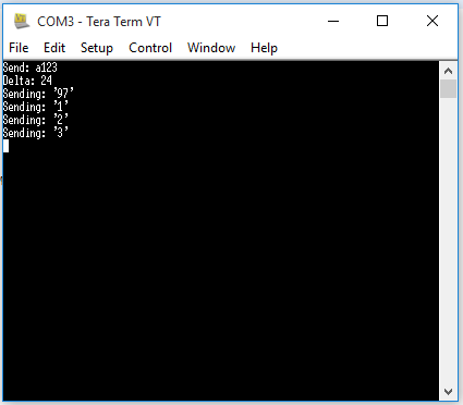
UARTprintf("Enviada: a%u\n", numeroEnviado);
start = TimerValueGet(TIMER1_BASE, TIMER_A);
converteFloatChar(numeroEnviado, pui32DataTx, 'a');
delta = TimerValueGet(TIMER1_BASE, TIMER_A) - start;
UARTprintf("Delta: %u\n" , delta);
IntMasterEnable();
SSIIntEnable(SSI1_BASE, SSI_RXFF);
IntEnable(INT_SSI1);
while(ui32Index<strlen(pui32DataTx)){
UARTprintf("Enviando: '%u' \n", pui32DataTx[ui32Index]);
SSIDataPut(SSI1_BASE, pui32DataTx[ui32Index]);
SSIDataPut(SSI0_BASE, pui32DataTx[ui32Index]);
SSIDataPut(SSI1_BASE, pui32DataTx[ui32Index]);
SSIDataGet(SSI1_BASE, &pui32DataRx[ui32Index]);
ui32Index++;
}
return 0;
}
Inside the while routine to send data as Slave, the slave needs the clock wich is generated by master, so master keep sending some dummy data during it (this isn't ideal for my application but it was a suggestion from a TI employee and now I can finally send using Slave, ty).
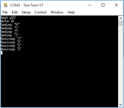
This is what is printed on my serial port:
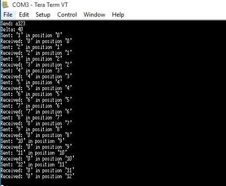
It seems like it loses the first data and repeat the third one because of that. Also, I tried to comment one line inside the while:
	while(ui32Index<strlen(pui32DataTx)){
		UARTprintf("Enviando: '%u' \n", pui32DataTx[ui32Index]);
		SSIDataPut(SSI1_BASE, pui32DataTx[ui32Index]);
		SSIDataPut(SSI0_BASE, pui32DataTx[ui32Index]);
		SSIDataPut(SSI1_BASE, pui32DataTx[ui32Index]);
//		SSIDataGet(SSI1_BASE, &pui32DataRx[ui32Index]);
		ui32Index++;
	}
Because I think this line should be only inside the interrupt, but if I do this the interrupt is called 2 times and I didn't understand why this is happening.

So, I didn't have success on my attempts. Does anybody have any suggestion?
Mayli.