This thread has been locked.

If you have a related question, please click the "Ask a related question" button in the top right corner. The newly created question will be automatically linked to this question.

Is SYSCLK pre divided PWMCLK as shown in clock tree as (N%2) prior to setting PWMCC bit 8?

Guru 55913 points

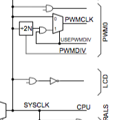
The TM4C1294 main clock tree figure 5-5 shows SYSCLK pre-divided (N%2) for PWMCLK and line exiting bottom of block labeled PWMDIV. The confusing part is no other blocks in tree with N show a divisor so it make seem as if SYSCLK logically is pre-divided by design. If the intent is PWMDIV infers  PWMCC register sets the divisor then the clock tree should perhaps indicate such.

Does clock tree infer a 120mHz SYSCLK will actually be 60mHz PWMCLK before setting PWMCC bit 8? 

Strange thing 120mHz setting PWMCC bit 8 produces 80us period, 12.5kHz assuming 4800 ticks per second. However (SYSCLK%4) should be 30mHz(33.3ns) PWMCLK, seemingly 2400 ticks but the actual period being produced is not a multiple of the ticks or.....

33.3ns * 2400=(80us) and PWM generators are roughly producing a period 0.390ms.

  • Hello BP101

    I think that is an error in the data sheet. I don't believe a pre divider is applied on the PWM clock other than PWMDIV as configured in the PWMCC register

    Regards
    Amit
  • BP101 said:
    120mHz setting PWMCC bit 8 produces 80us period, 12.5kHz assuming 4800 ticks per second

    A 12.5KHz frequency yields an 80µS period.

    "How and where" does the (assumption) of "4800 ticks per second" arrive?

  • Hi Amit,

    Should not the frequency (period) remain constant at either PWMCLK rate and the PWM tick width only change?

    60,000,000/12500 = 4800tps, 16.6ns tick width ----- 30,000,000/12500 = 2400tps, 33.3ns tick width.

    The BLDC tachometer uses pole counts in the speed calculation and dividing by 4 versus 2 produces close to the proper RPM with 60mHz PWMCLK or PWMCC set 0x00000100. Speed formula poles count divide by 2 for 50Mhz PWMCLK of LM3S. The TM4C1294 PLL 480mHz/4 should produce SYSCLK of 120mHz. Tiva clock set function is highly complicated and not so easily to follow source listing.

    So very strange our TM4C1294 60mHz PWMCLK is producing exactly 1/2 the RPM speed reading for 60Mhz PWMCLK. Do expect RPM should be a little off for the 10mHz PWMCLK increase but not exactly 1/2.
  • Hello BP101,

    Could it be that the PWM is being used in Up-Down mode rather than Down mode and hence there is a factor of 1/2

    Regards
    Amit
  • Hi,

    Let's see the picture in cause (part of it):

    This shows up like there is a direct connection from SysCLK to PWMCLK, marked with "0", while the other marked with "1" belongs to variable USEPWMDIV.

    The user manual says that if USEPWMDIV is 0, the system clock is the source clock for PWM, while if 1, the divider comes into play, with the default value "0" dividing by 2.

    Do you set by mistake USEPWMDIV in this case? (or something wrong in driverlib, not checked...)

  • Hi Amit,

    I found why the period was wrong at 30Mhz, also required set #define PWM_CLK_WDTH for 33U versus 16U. PWM_SYSCLK_DIV_4 is now keeping 12.5kHz period 80us but the RPM readout divided again in half reducing even lower. On the face It looks like you are right about the N%2 in clock tree but I'm to scared to test the bridge at 120mHz PWMCLK if that is what results PWMRCC 0x0.

    The good part is the rotor speed does not seem to change. The 24v DC power supply typically ran 22v loaded now runs at 24v. That may be due to seeing slower and consistent 35us FET on times at the lower tick count. BLDC is running more efficiently as a result.

  • Hi Petri,

    That "0-1" gate and text is a bit ambiguous. Was already using PWMDIV/2 and wondering is SYSCLK/2 default for USEPWMDIV=1 inferring 60mhz and asserting PWM_SYSCLK_DIV_2 = 30Mhz and not 60Mhz. That %2N makes it seem like that could be the case but how can we really know for sure unless somehow could count PWM ticks in one second.

    The only real thing for sure is the duty cycle is close to 43% with PWMDIV/4 and roughly 28% with PWMDIV/2.
  • Is it even (remotely) possible that, "PWM_SYSCLK_DIV_4" yields a PWM frequency of 12.5KHz as poster reports? (If the SYSCLK was 50KHz - that would be more likely.)

    Poster weaves in: RPM readout, rotor speed, power supply voltage AND "FET on times" - and then claims BLDC runs more efficiently!

    Focus and KISS flee (properly) in terror... (along w/this reporter)

  • The (PWMGenPeriodSet) and (PWMPulseWidthSet) loads an 80us period @12.5Khz. Perhaps the tick rate is what changes to PWMCLK divisor as expected it should and had simply neglected to change #defines after setting the divisor higher.

    That directly impacted the period and frequency but not the rotor RPM. 24v 14a switching power supply not sagging by over 2v is a first in years. I'd say that is a sign of improved efficiency in PWM controller behavior.

    PWM_CLK 30000000 ---- PWM_CLK_WIDTH 33U
  • Hi,

    Involving dividers would reduce the resolution of any other adjustment with PWM, possibly loosing/lowering some parameters. While the systick count is less that 2^16, I would not think about using dividers - please note I'm not expert in motors, but have some experience with high power converters, where the resolution is better to be higher, I think same here...

  • Hello BP101

    PWMGenPeriodSet and PWMPulseWidthSet do not load the pre-dividers for the PWM Clock. It loads the dividers for the final PWM based on the PWMClock

    Regards
    Amit
  • Hi Petri,

    Did get brave after reviewing math for 30/60Mhz and set PWM_CLK_DIV_1 for 120mHz and other PWM #defines accordingly. The same period was produced 12.5kHz (80us) and the PWM tick count obviously doubled to 9600tps as a result. However the 60mHz PWMCLK rotor pole count set  %4 produced very close to the original 50mHz PWMCLK rotor speed. It must be the ADC oversampling interrupt interval at 4x has influence as the LM3S refused to go above 2x ADC hardware oversampling in the BEMF edge counts

    That said your explanation of clock tree %2N was closest to the actual register PWMCC  USEPWMDIV without a foot note (x) to explain. Though Amit makes similar connection without ready access to an direct explanation of underlying text so you both get green stamps this forum!


  • BTW: Thanks for question as review of 30mHz PWMCLK produced typical 14us FET on time and 60Mhz produced 32-35us FET on times at the very same 80us period. 120Mhz PWMCLK also produced typical 14us FET on times but suspect the ADC sample bus voltage 24V was simply a bit more accurate and not ever dropping to 22v during MUT.

    So you too get the green stamp of approval and we all WIN in a GREEN world of high efficiency. MIT professor interview with Louisiana college professors : A better need to foster DOE objectives and drive commercialization of products must start in the educational facilities across this nation before we meld down the planet!