This thread has been locked.

If you have a related question, please click the "Ask a related question" button in the top right corner. The newly created question will be automatically linked to this question.

Different capture time using PING-PONG mode with ADC+DMA

Hello all.

I am trying to capture, perfectly synchronous, two channels (in the same ADC) - 128 samples data buffer at 250KHz using a timer triggering the ADC+DMA.

However, I have seen some jitter between the times to capture the whole buffer for the PING and the PONG block.

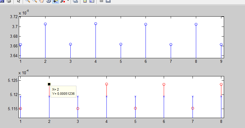
I toggled a pin in the ADC interrupt and I am seeing this:

  • Above: difference
  • Below: 
    1. O Red: Time to capture the block (measured)
    2. X Blue: Expected and measured on an external device

The only reference in the forum about this issue is in this thread, where they state that with ADC  ALWAYS jitter dissappears:

I would like to know what is the official statement about this issue or if there is a chance to remove it.

Actually, I am still not sure why jitter is present and different in PING and PONG modes...any register load?

Best Regards

  • Hello PAk,

    If I read the 2nd plot correctly, there is a +/- 5 us difference from the expected value. Is that correct?

    Regards
    Amit
  • Actually the data I am getting from the scope and processed in MATLAB:

    Time_between_blocks (toggle) =
    
                   0.000511515
                    0.00051236
                   0.000511515
                   0.000512365
                    0.00051152
                    0.00051236
                    0.00051152
                    0.00051236
    
    diff(Time_between_blocks)
    
    ans =
    
         8.44999999999861e-007
        -8.44999999999752e-007
         8.49999999999723e-007
        -8.44999999999752e-007
         8.39999999999782e-007
        -8.39999999999782e-007
         8.39999999999782e-007

    The grpah was the difference with the central (expected signal), so there is a PHASE adding in it.

    Thank you Amit.

  • PAk said:
    O Red: Time to capture the block (measured)

    How is the measured "capture" time taken?

    i.e. is when the ADC sample is taken, or at the end of a DMA block?

  • Chester Gillon said:
    How is the measured "capture" time taken?

    i.e. is when the ADC sample is taken, or at the end of a DMA block?

    End of DMA block at the beggining of the interrupt.
    I am attacking an external DDS which provides an EoC signal, which is pretty stable, that is one reference I use (blue x on the plot).

  • In case you owuld like to test it, every block is 128 samples at 250KHz.....using:

    ulPeriod_timer = 480;
    dutyCycle_timer = 240;
    
    	TimerLoadSet(TIMER1_BASE, TIMER_A, ulPeriod_timer - 1);
    	TimerMatchSet(TIMER1_BASE, TIMER_A, dutyCycle_timer); 


  • Hello PAk

    Note that when processing a Ping Pong buffer, the CPU is processing an if-if condition in the interrupt handler. Is the GPIO toggle always in the unconditional part of the interrupt handler or in the conditional part of the interrupt handler?

    Regards
    Amit
  • Amit Ashara said:
    Hello PAk

    Note that when processing a Ping Pong buffer, the CPU is processing an if-if condition in the interrupt handler. Is the GPIO toggle always in the unconditional part of the interrupt handler or in the conditional part of the interrupt handler?

    Regards
    Amit

    First thing after the block check, otherwise I would get a toggle every ADC conversion:

    ulMode = uDMAChannelModeGet(UDMA_CHANNEL_ADC2 | UDMA_ALT_SELECT);
    
    		if (ulMode == UDMA_MODE_STOP)
    		{
    
    			toggle();
    
    
    ...
    }

  • Hello PAk

    Toggle the GPIO as the first thing to be done in the interrupt handler, outside of the if statement(s)

    Regards
    Amit
  • Amit Ashara said:
    Hello PAk

    Toggle the GPIO as the first thing to be done in the interrupt handler, outside of the if statement(s)

    Regards
    Amit

    If I do that I get a toggle for every ADC sample!!

  • Hello PAk,

    That is not correct unless the transfer size is 1. If the transfer size is N (where N is more than 1), then the interrupt must be fired at N samples.

    Regards
    Amit
  • Amit Ashara said:
    Hello PAk,

    That is not correct unless the transfer size is 1. If the transfer size is N (where N is more than 1), then the interrupt must be fired at N samples.

    Regards
    Amit

    Transfer Size is (2 * NUM_SAMPLES) since I am reading two channels. Then, why am I getting an interrupt every pair of ADC sample?

  • Hello PAk

    And what is the NUM_SAMPLES you are reading from the ADC controller and at what interval is ADC is sampling?

    Regards
    Amit
  • Amit Ashara said:
    Hello PAk

    And what is the NUM_SAMPLES you are reading from the ADC controller and at what interval is ADC is sampling?

    Regards
    Amit

    Hello Amit, I corrected the issue with the interrupt. I was using ADCIntClear and ADCIntEnable, instead of ADCIntClearEx and ADCIntEnableEx.

    Now the time jitter has improved decreased, however, the time is not constant!!!(The toggle is at the beggining of the interrupt - reed mark below):

  • Hello PAk,

    What is the CPU doing when DMA is processing? Clearly it would also be accessing the SRAM and this may change the relative position of the DMA Done.

    Regards
    Amit