This thread has been locked.

If you have a related question, please click the "Ask a related question" button in the top right corner. The newly created question will be automatically linked to this question.

Deep Sleep Mode UART DMA Data Corruption

Dear Support,

We are experiencing unreliable UART DMA communication that only occurs when we enable Deep Sleep.  The link seems fine in normal Sleep mode.  Specifically, about .3% of our 128 byte packets have 1 byte duplicated.  We don't see dropped bytes or bit errors - just a duplicate character - kind of strange.  The UART is configured for 115k baud, 1 stop bit, no parity.  We are aware of the Errata DMA#02 which requires the deep sleep clock source to be the same as the run mode source.  We are using the PIOSC at 16 Mhz for both run mode and deep sleep.  We have logged the data being received by the UART and have verified no extra byte exists, but this duplicate byte is in the DMA receive buffer.   Are there other relevant erratas?  What code would you most like to see?

Thanks,

Brett

  • Brett,

    I tried UART DMA with deep sleep before, and the LCD displayed what I transmitted on UART0. I used LPIOSC (33kHz) as the clock source:

    SysCtlDeepSleepClockConfigSet(SYSCTL_DSLP_DIV_1 | SYSCTL_DSLP_OSC_INT30 | SYSCTL_DSLP_PIOSC_PD);

    Regards,
    QJ
  • Thanks for your response QJ.  Your experiment shows the peripheral can do a DMA transmit with deep sleep enabled.  I'm thinking there are still significant differences between that experiment and what we're doing - we are getting a duplicate character using a fast 115k baud rate and the 16 Mhz PIOSC.  We are going to experiment with a bigger arbitration size.  Right now we are using 2.  Note, we are using ping pong mode.  If you have any other thoughts, please let us know.  Thanks, Brett

           // select the primary control structure

           // select 8-bit data size

           // no source address increment (source is UART4DR)

           // dest address increment of 8 (1 8-bit byte per transfer)

           // arbsiz is 2 to match the RX FIFO interrupt threshold level of 2 bytes (1/8th of the 16 byte FIFO)

           uDMAChannelControlSet( (UDMA_CH18_UART4RX | UDMA_PRI_SELECT), (UDMA_SIZE_8 | UDMA_SRC_INC_NONE | UDMA_DST_INC_8 | UDMA_ARB_2)) ;

           uDMAChannelControlSet( (UDMA_CH18_UART4RX | UDMA_ALT_SELECT), (UDMA_SIZE_8 | UDMA_SRC_INC_NONE | UDMA_DST_INC_8 | UDMA_ARB_2)) ;


  • Hello Brett

    There is a known errata on using peripheral with deep sleep and DMA. If the device being used is TM4C129x please check DMA#02

    Regards
    Amit
  • Hi Amit,

    You mean this?

    DMA#02 :
    DMA#02 μDMA Data may be Corrupted if Transferred or Received While Entering or Exiting
    Deep Sleep Mode
    Revision(s) Affected: 1, 2, and 3.
    Description: Transferred or received data using the μDMA from either the UART or the SSI
    peripherals may get corrupted when entering Deep Sleep mode from Run mode or
    exiting Deep Sleep mode to Run mode if the Run mode clock configuration is not the
    same as the Deep Sleep mode clock configuration.
    Workaround(s): Program the Run mode clock configuration to match the Deep Sleep mode clock
    configuration right before entering Deep Sleep mode

    We have configured the UART to use the PIOSC in both run and sleep and deep sleep modes. The data corruption -- always an extra and duplicate byte never flipped bits or a dropped byte -- occurs only when deep sleep is the sleep mode used.

    The duplicate byte is scattered through the 156 byte stream of bytes, there doesn't seem to be any pattern as to where it will appear.

    The byte stream is an incoming byte stream from a cell modem. I have monitored the serial data from the cell modem and it does not have the duplicate byte present.

    Marc.
  • Amit,

    As we said in the original post:

    "We are aware of the Errata DMA#02 which requires the deep sleep clock source to be the same as the run mode source.  We are using the PIOSC at 16 Mhz for both run mode and deep sleep. "

    It is our interpretation of the errata note that using the PIOSC clock for run and deep sleep for both run mode and deep sleep mode should avoid the issue, yet we still have a problem.

    Can you tell us if there are any other factors, such as baud rate, DMA arbitration size, ping-pong buffer size, frequency of entering or exiting deep sleep mode, or anything else, that has an effect on the reliability of receiving serial communication using the DMA in deep sleep mode?

    Edward Blair
    Sr. Firmware Engineer
    Davis Instruments.

  • Hello Edward,

    I know that you had already posted that. But looking at the symptoms and knowing that there were no other known causes for this issue, could it be possible that the clock source may have been reconfigured. Can you please send the register value of the UART module and the System Control Register for DSCLKCFG and RSCLKCFG when the issue occurs?

    The other factors do not play a part except to change the time of occurrence. So it may artificially reflect as the issue has got fixed.

    Also can you confirm that the byte is not replicated on the UART bus?

    Regards
    Amit
  • First, I have monitored the data stream from the cell modem to the TI microprocessor. The duplicated byte is not present in the data stream that is being supplied to the TI microprocessor. The duplicate byte never appears when the micro is running in regular or sleep mode.

    Next, I do not have the actual register settings at the time the error occurs.

    However, the UART registers, uDMA registers, and System Control registers are set at init time, shortly after reset, and are not changed on the fly.

    Here are the source code lines -- TIVA-C library functions are used -- that set the System Control registers:

    SysCtlClockOutConfig((SYSCTL_CLKOUT_EN | SYSCTL_CLKOUT_SYSCLK), 2);
    SysCtlClockFreqSet((SYSCTL_OSC_INT | SYSCTL_USE_OSC), 16000000);

    SysCtlAltClkConfig(SYSCTL_ALTCLK_PIOSC) ;

    SysCtlDeepSleepClockConfigSet( 1, SYSCTL_DSLP_OSC_INT );
    SysCtlSleepPowerSet((SYSCTL_SLPPWRCFG_FLASHPM_SLP | SYSCTL_SLPPWRCFG_SRAMPM_LP)) ;
    SysCtlDeepSleepPowerSet((SYSCTL_DSLPPWRCFG_FLASHPM_SLP | SYSCTL_DSLPPWRCFG_SRAMPM_NRM | SYSCTL_DSLPPWRCFG_TSPD)) ;


    UART register set source code lines:

    // enable the clock for UART4
    // can't touch this UART4 for 5 clocks cycles after the enable or we get a bus fault!
    SysCtlPeripheralEnable(SYSCTL_PERIPH_UART4);

    while (!SysCtlPeripheralReady(SYSCTL_PERIPH_UART4)) ;

    SysCtlPeripheralReset(SYSCTL_PERIPH_UART4);

    // UART4 must work in sleep mode!
    SysCtlPeripheralSleepEnable(SYSCTL_PERIPH_UART4);
    SysCtlPeripheralDeepSleepEnable(SYSCTL_PERIPH_UART4) ;

    while ( false == SysCtlPeripheralReady(SYSCTL_PERIPH_UART4 ) ) ;

    // ensure the UART is disabled!
    UARTDisable(UART4_BASE) ;

    // ensure this is set to the right value!
    // note we use the PIOSC as this is present in low power modes!
    // UART4 must operate in all power modes!
    UARTClockSourceSet( UART4_BASE, UART_CLOCK_PIOSC ) ;

    HWREG(UART4_BASE + UART_O_IFLS) = ( UART_FIFO_RX4_8 | UART_FIFO_TX4_8 ) ;

    // the function UARTConfigSetExpClk() function below disables the UART before changing anything
    // but in case the library code changes...
    // disable UART4 before configuring its clocks?
    UARTDisable(UART4_BASE);

    // note the presence of UART_LCRH_FEN! to turn on the FIFO's!
    UARTConfigSetExpClk(UART4_BASE, sysClkRate, V_TELIT_MODEM_BAUD_RATE, (UART_LCRH_FEN |
    UART_CONFIG_WLEN_8 | UART_CONFIG_STOP_ONE | UART_CONFIG_PAR_NONE));

    // because UARTConfigSetExpClk() above leaves the UART enabled we disable it again here
    // this disables the FIFO's too!
    // disabling the UART is important for the UARTTxIntModeSet() below!
    UARTDisable(UART4_BASE) ;

    // the UART must be disabled for the following function!
    UARTTxIntModeSet(UART4_BASE, UART_TXINT_MODE_EOT) ; // trigger when TX FIFO is empty

    // before enabling UART4 interrupt
    // select which interrupts we want the UART to recognize
    // enable the DMARX interrupt along with the OVERRUN, BREAK and FRAMING interrupts
    HWREG(UART4_BASE + UART_O_IM) |= ( UART_INT_DMARX | UART_INT_OE | UART_INT_BE | UART_INT_FE ) ;

    // enable THE UART4 interrupts at the interrupt controller
    IntEnable( INT_UART4 ) ;

    telit_dma_init ( ) ;

    // now do this
    UARTDMAEnable(UART4_BASE, UART_DMA_RX) ;

    // enable the UART and the RX and TX channels!
    HWREG(UART4_BASE + UART_O_CTL) &= ~(UART_CTL_UARTEN) ;
    // make the changes
    HWREG(UART4_BASE + UART_O_CTL) |= (UART_CTL_RXE | UART_CTL_TXE);
    // enable
    HWREG(UART4_BASE + UART_O_CTL) |= (UART_CTL_UARTEN) ;

    // sets FEN bit in LCRH and UARTTXE, UARTRXE and UARTEN in CTL
    UARTEnable(UART4_BASE) ;


    Below are debug output of the various uDMA and UART4 registers:

    [Mon Jul 18 11:55:54.106 2016] [ 1828] uDMA Control Base 20022000
    [Mon Jul 18 11:55:54.106 2016] [ 1192] Primary Control 40010000 2000E00F 0C00FFF3 00000000
    [Mon Jul 18 11:55:54.106 2016] [ 1208] Alternate Control 40010000 2000E40F 0C00FFF3 00000000
    [Mon Jul 18 11:55:54.106 2016] [ 1214] &RxBuffer 2000DC10
    [Mon Jul 18 11:55:54.106 2016] [ 1867] pRead 2000DC10
    [Mon Jul 18 11:55:54.106 2016] STAT 001F0001
    [Mon Jul 18 11:55:54.106 2016] CFG 00000000
    [Mon Jul 18 11:55:54.106 2016] CTLBASE 20022000
    [Mon Jul 18 11:55:54.106 2016] WAITSTAT 03C7CF00
    [Mon Jul 18 11:55:54.106 2016] USEBURSTSET 00000000
    [Mon Jul 18 11:55:54.106 2016] REQMASKSET 00000000
    [Mon Jul 18 11:55:54.106 2016] ENASET 00044000
    [Mon Jul 18 11:55:54.106 2016] ALTSET 00000000
    [Mon Jul 18 11:55:54.106 2016] PRIOSET 00000000
    [Mon Jul 18 11:55:54.106 2016] ERRCLR 00000000
    [Mon Jul 18 11:55:54.121 2016] CHMAP0 00000000
    [Mon Jul 18 11:55:54.121 2016] CHMAP1 22000000
    [Mon Jul 18 11:55:54.121 2016] CHMAP2 00000200
    [Mon Jul 18 11:55:54.121 2016] CHMAP3 00000000

    [Mon Jul 18 11:55:54.121 2016] RSR 00000000
    [Mon Jul 18 11:55:54.121 2016] FR 00000197
    [Mon Jul 18 11:55:54.121 2016] IBRD 00000008
    [Mon Jul 18 11:55:54.121 2016] FBRD 0000002C
    [Mon Jul 18 11:55:54.121 2016] LCRH 00000070
    [Mon Jul 18 11:55:54.121 2016] CTL 00000311
    [Mon Jul 18 11:55:54.121 2016] IFLS 00000012
    [Mon Jul 18 11:55:54.121 2016] IM 00010680
    [Mon Jul 18 11:55:54.121 2016] RIS 00000000
    [Mon Jul 18 11:55:54.121 2016] MIS 00000000
    [Mon Jul 18 11:55:54.121 2016] DMACTL 00000001
    [Mon Jul 18 11:55:54.121 2016] CC 00000005

    Marc.
  • Hello Marc

    Thanks for the data. I was expecting the value of the registers when the issue occurs, to be 100% sure.

    Also I had requested the value of the register DSCLKCFG and RSCLKCFG when the issue occurs?

    Regards
    Amit
  • If you need the register values at the time the error occurs I'll have to write code to emit the register values. The error occurs when receiving an incoming stream of bytes -- 156 bytes -- and the code that processes these doesn't know the error is present until after the bytes have been received into the SRAM uDMA buffer and then transferred to the the higher level code that actually parses the stream of bytes and then determines there is a problem with the data.

    But as I stated before once the registers are set up they are not changed. The data corruption event never occurs during regular mode or when sleep mode is used. Other than commenting out the call to put the micro into sleep mode to stay in regular mode, or sub a library call to put the micro into deep sleep mode instead of sleep mode, the code is the same.

    Do you need the actual register values at the (approx) time the error happened?

    I included the lines that call the library code to set the DSCLKCFG register.

    However, I overlooked the library call that sets the peripheral clock gating in sleep and deep sleep modes. Here it is:

    SysCtlPeripheralClockGating(true);

    Marc.
  • Hello Marc

    I understand that additional code has to be written, but to be sure there is no SW issue, I still need to check.

    Also as you mentioned it does not occur during Sleep Mode. Are you sure that the

    1. Deep Sleep clock for the peripherals is correctly enabled

    Regards
    Amit
  • Ok. I'll have to check with my managers to get their permission to write the extra debug code. I don't expect they will object.

    The peripherals -- uDMA, UART4, and the GPIOA (and in fact all other peripherals that are expected to operate in both sleep modes) -- are all set to operate in both sleep and deep sleep mode.

    Marc.
  • Oh, just so it is clear, there will be some time -- milliseconds -- between the time the duplicate byte is created and when the higher level code determines the stream of bytes (document in our nomenclature) is invalid.

    Thus the special register dump code will be dumping the register contents some milliseconds after the error has occurred.

    Is this ok?

    Marc.
  • Hello Marc,

    Yes, that is correct that there would be some delay before the CPU gets the required information

    Regards
    Amit
  • Ok, the firmware ran overnight and the data corruption occurred 36 times.

    Here is the System Control, uDMA control structure content (which I don't think you asked for but I thought I'd toss it in), and the UART and uDMA registers. Note I have added at the bottom a sample corrupted "document".

    [Wed Jul 20 18:51:08.833 2016] RSCLKCFG 20000013
    [Wed Jul 20 18:51:08.833 2016] MEMTIM0 00300030
    [Wed Jul 20 18:51:08.833 2016] PLLFREQ0 00000014
    [Wed Jul 20 18:51:08.855 2016] ALTCLKCFG 00000000
    [Wed Jul 20 18:51:08.855 2016] DSCLKCFG 00000000
    [Wed Jul 20 18:51:08.855 2016] SLPWRCFG 00000023
    [Wed Jul 20 18:51:08.855 2016] DSLPPWRCFG 00000120
    [Wed Jul 20 18:51:08.855 2016] [ 1199] Primary Control 40010000 2000E00F 0C00FFF3 00000000
    [Wed Jul 20 18:51:08.855 2016] [ 1215] Alternate Control 40010000 2000E40F 0C00EFF3 00000000
    [Wed Jul 20 18:51:08.855 2016] [ 1221] &RxBuffer 2000DC10
    [Wed Jul 20 18:51:08.855 2016] STAT 001F0001
    [Wed Jul 20 18:51:08.855 2016] CFG 00000000
    [Wed Jul 20 18:51:08.855 2016] CTLBASE 20022000
    [Wed Jul 20 18:51:08.855 2016] WAITSTAT 03C7CF00
    [Wed Jul 20 18:51:08.855 2016] USEBURSTSET 00000000
    [Wed Jul 20 18:51:08.855 2016] REQMASKSET 00000000
    [Wed Jul 20 18:51:08.855 2016] ENASET 00044000
    [Wed Jul 20 18:51:08.855 2016] ALTSET 00040000
    [Wed Jul 20 18:51:08.855 2016] PRIOSET 00000000
    [Wed Jul 20 18:51:08.855 2016] ERRCLR 00000000
    [Wed Jul 20 18:51:08.855 2016] CHMAP0 00000000
    [Wed Jul 20 18:51:08.855 2016] CHMAP1 22000000
    [Wed Jul 20 18:51:08.855 2016] CHMAP2 00000200
    [Wed Jul 20 18:51:08.855 2016] CHMAP3 00000000
    [Wed Jul 20 18:51:08.855 2016] RSR 00000000
    [Wed Jul 20 18:51:08.855 2016] FR 00000197
    [Wed Jul 20 18:51:08.855 2016] IBRD 00000011
    [Wed Jul 20 18:51:08.855 2016] FBRD 00000017
    [Wed Jul 20 18:51:08.855 2016] LCRH 00000070
    [Wed Jul 20 18:51:08.855 2016] CTL 00000311
    [Wed Jul 20 18:51:08.855 2016] IFLS 00000012
    [Wed Jul 20 18:51:08.855 2016] IM 00010680
    [Wed Jul 20 18:51:08.855 2016] RIS 00000000
    [Wed Jul 20 18:51:08.855 2016] MIS 00000000
    [Wed Jul 20 18:51:08.855 2016] DMACTL 00000001
    [Wed Jul 20 18:51:08.855 2016] CC 00000005
    [Wed Jul 20 18:51:08.855 2016]
    [Wed Jul 20 18:51:08.855 2016] ######
    [Wed Jul 20 18:51:08.855 2016]

    95F501039400288B2A90573D008000000000008500842A9057024142434445464748494A4B4C4D4E4F505152535455565758595A5B5C5D5E5F606162636465666768696A6B6C6D6E6F707172737475767778797A7B7C7D7E4142434445464748494A4B4C4D4E4F50515253545556 57 57 (this 2nd "57" is the manifestation of the duplicate byte problem)
    58595A5B5C5D5E5F606162636465666768696A6B6C6D6E6F707172737475767778797A7B7C7D7E41424300A9

    If you need anything else just ask.

    Marc.
  • Hello Marc,

    Thanks for the detailed register values. They are all OK. To understand and try to replicate the issue, I want to know what is the cause of wakeup from deep sleep. Is it the RXDMA done interrupt from the UART that causes the CPU to wake up or there are other sources of wakeup?

    Also as you mentioned, that you use Sleep and Deep Sleep Mode both. Is there any co-relation of the transition between the Active, Sleep and Deep Sleep mode, e.g. the issue occurs if there is Sleep -> Active -> Deep Sleep mode transition?

    Regards
    Amit
  • I have no idea of what wakes the processor up from Deep Sleep mode. It could be the RXDMA done interrupt or it could be the RTC timer interrupt, or another interrupt (from the mesh radio).

    We are not using sleep/deep sleep mode at the same time. There are function calls to library code to either put the micro into sleep mode, or deep sleep mode, or for testing to not put the micro into any sleep mode. While I can comment the line that puts the micro into deep sleep mode and uncomment the line that puts the micro into sleep mode, or comment both sleep lines of code and keep the micro awake all the time, there is no facility for invoking sleep and deep sleep concurrently or in any alternating fashion. It takes a rebuild of the firmware and a reflashing of the code image to to change the type of sleep used.

    Marc.
  • Hello Marc,

    OK, so correct me (if my understanding is not up to speed). The application may use either sleep and active state or deep-sleep and active state. But it does not have an option to use either sleep/deep sleep and awake under some code condition.

    If that is the case then once cause I can eliminate. Now let us eliminate the wake up causes. Can you perform the same test with only RXDMA done interrupt as the wakeup source, or selectively eliminate the wake up sources till we arrive to most minimal.

    Please note that I do not have your setup, so all i can do is connect two launchpads and see if I can replicate the issue. Since it will be a scratch code, I need to keep it as simple as possible.

    Regards
    Amit
  • Correct. The type of sleep, or no sleep at all, is not something that is controllable outside of a physical code change. There is no on the fly, or run time decision to use one type of sleep or another, or to use no sleep at all.

    While the RXDMA done interrupt like any other interrupt can wake the processor in sleep mode, the RXDMA done interrupt is not likely the cause of the wake up. The two Ping Pong buffers are 1024 bytes in size and the largest document that is currently being transmitted and in which the duplicate byte appears, is just 156 bytes in size. The documents arrive ever 15 seconds so it takes a fraction over 6 documents (and around a minute and a half) before one buffer is full and the uDMA switches to the other buffer.

    The more likely source of a wake up is the RTC timer interrupt which is configured to fire every few milliseconds.

    There is no way I can disable this interrupt as the system is highly dependent upon this interrupt to wake the embedded OS which then dispatches any processes that are ready to run.

    The generating the test documents, the sending of them to the back end, the receiving/processing of the replies -- in which the duplicate byte sometimes appears -- and a number of other critical processes, all require the OS be invoked at pretty precise intervals.

    Marc.
  • Hello Marc

    Marc Warden said:
    highly dependent upon this interrupt to wake the embedded OS

    And that does complicate the issue as I did not anticipate an embedded OS (which one do you use, if it cannot be disclosed, I understand).

    Marc Warden said:
    The documents arrive ever 15 seconds so it takes a fraction over 6 documents (and around a minute and a half) before one buffer is full and the uDMA switches to the other buffer.

    Even the failure is very rare on the system. So it could be an interaction of wake from deep sleep and DMA transfer that could be the issue. In the last register snapshot that you had sent, I saw that SLPPWRCFG was set to 0x23 and I would assume that when using sleep mode it will have the value 0x20? That is because in Deep Sleep mode DSLPPWRCFG was set to 0x120.

    Since Sleep mode uses the same RSCLKCFG register as run mode, I think the issue may not be manifesting but when using the Deep Sleep Clock Config, DSCLKCFG, there is an issue occurring due to clock switching. I also noticed that the Divided clock is being generated using DIVSCLK. Is it possible to monitor the same on a scope which can capture glitches or clock elongation?

    Regards

    Amit

  • We are using Contiki for the embedded OS.

    My WAG is the problem is *not* uDMA related but is with the UART peripheral and probably -- given how infrequent the duplicate byte problem appears -- from waking up from deep sleep mode.

    The duplicate byte I believe can be explained by the UART signaling the uDMA controller to transfer a byte from the RX FIFO and supplying the byte from the RX FIFO but failing to increment its internal hardware read pointer. Thus the next transfer has this internal read pointer pointing at the same byte that was just transferred and of course transferring it again. Hence the duplicate byte. Never a corrupted byte or a missing/dropped byte.

    And of course, the 2nd transfer of the duplicate byte does then have the UART incrementing its internal hardware read pointer and subsequent transfers from the RXFIFO occur with no problems.

    This suspected transfer without the corresponding RX FIFO read pointer increment could occur at the time the processor switches from deep sleep mode to run mode.

    I can I believe monitor the DIVSCLK output provided it works with the PIOSC as the clock source. I just checked and it does work with the PIOSC as the system clock but the DIVSCLK signal is not synchronized to the System Clock. Does this mean that a possible enlongated or glitchy PIOSC clock pulse will not show up on this output?
  • Hello Marc,

    Not necessarily. If that is the case then it should occur in Active Mode as well. What I believe is happening is that there is a clock pulse which gets supplied to the DMA and not to the UART causing the data to be read out twice.

    Regards
    Amit
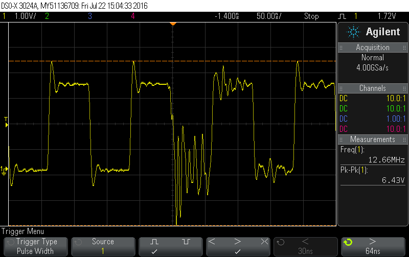
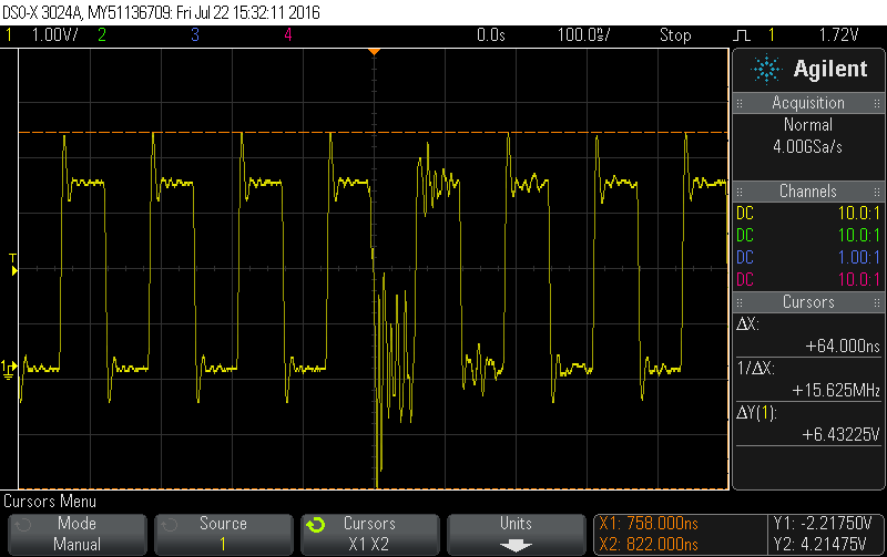
  • Ok, I have run the firmware with a scope connected and just a few minutes ago the scope triggered with a narrow pulse. The low signal level is noisy, too. And I checked and there was a duplicate byte error at about the same time the scope triggered.

    I have a screen shot saved to a PNG file. How can I get this to you?
  • Hello Marc,

    Click on the "Use rich formatting" on the bottom right of the reply box, and then attach the image.

    Regards
    Amit
  • Here are the images:

  • Hello Marc,

    I was expecting a missing clock or elongated edge, but this seems that the clock frequency changed for no apparent reason. And this is the system clock on the DIVSCLK, right?

    Regards
    Amit
  • The scope lead is connected to a wire that is soldered to the micro's DIVSCLK pin. BTW, this ouput is the PIOSC divided by 2. There apparently is no support for a divide by 1 output.
  • Hello Marc

    Yes, I do see 8Mhz based on the scope's horizontal resolution and the edges of the clock. But the multiple edges do not make sense. Is there a Crystal on your board. If yes then can you short the OSC0 pin to GND and if not then is OSC0 connected to GND?

    Regards
    Amit
  • There is no crystal on the board (other than a 32KHz crystal connected to pins XOSC0 and XOSC1) and OSC0 is floating.
  • Hello Marc

    While OSC0 as NC is an acceptable practice, I would strongly recommend OSC0 connected to GND. Also we are sure that the MOSC is not powered up (please check SYSCTL.MOSCTL register). The strange oscillations right at the same time of failure kind of bothers me with the fact the OSC0 is NC.

    I am trying to eliminate as many causes....

    Regards
    Amit
  • Hi Amit,

    A tech has grounded OSC0. The board is running as I type.

    There is no code to specifically power down the MOSC and to tell the TI part there is MOSC connected. The Main Oscillator Control Register defaults to 0x0000000C. Bits 3 and 2 are '1'. So, the power up default of this register defaults to the MOSC is not present and the MOSC circuit is powered down.

    Just to be safe I'll just go ahead and add a line of code to set this register to the desired value just in case.

    Marc.

  • Hello Marc,

    Let us monitor this run with the scope connected.

    Regards
    Amit
  • Hi Amit.

    I left the scope connected yesterday from 11am to after 10am today.

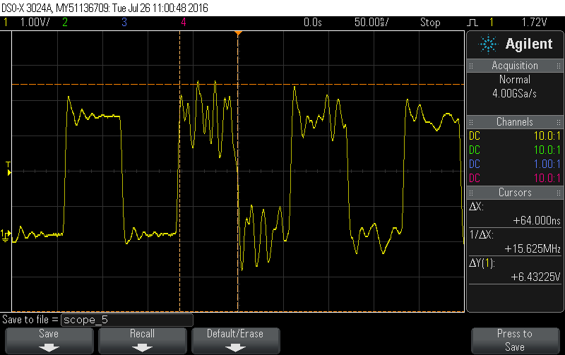
    The scope had triggered once yesterday before I left the office but there was no error. The "noise" appears to be a bit less as you can see from the image below.

    Upon arrival at the office today, Brett brought it to my attention the scope had triggered. I do not know at what time the scope triggered and thus can't say if there was an error associated with the triggering. Unfortunately, I can say though there were a number of errors. The 1st one was yesterday (Monday) at 17:20 then 20:06 with the last at 9:33 today (Tuesday).

    Brett insisted on double-checking the OSC0 was grounded and it was. The board designer confirmed this to both his and Brett's satisfaction.

    Because of this problem deep sleep is not an option and it was deep sleep we were counting on being able to use. We have a product with just regular sleep mode but the extra power consumption is not something anyone here is happy with.

    Where do we go from here? Where can we go from here?

    Marc.

  • Hello Marc,

    So there is no visible clock switching issue. Also since your use case involves an OS, it is not possible for us to reproduce the issue. The most we can do is to develop a bare metal test code with periodic interrupt from an internal timer and DMA for UART with the same deep sleep clock settings as yours and run it over extended period, to see if we can reproduce the issue.

    Also you are reading UART data register via the DMA to a 8 bit SRAM. The UARTDR has the status bit of the transaction in the next nibble. I would like that in your use case, read the UART data register as a 16 bit data and check the value of the nibble when the failure occurs.

    Regards
    Amit
  • Hi Amit.

    An absence of a clock switching issue has not been confirmed. The scope trigger was set to trigger with a 64ns (or greater) high pulse. I have not set the scope to trigger with too narrow a pulse or (if the scope supports it) a "glitch".

    In one case the scope did trigger with a (barely) too wide high pulse and there was an error that at least was in the right time window as best I could tell.

    The scope trace did show a bit of a step/ledge on the falling edge of the high pulse which made the pulse wider, wide enough to trigger the scope.

    I have to point out the incoming byte stream is without the error -- the duplicate byte -- so it is unlikely the error bit capture will be of any real value. Besides the UART error interrupts are enabled and there is code to detect an error, count it, and to read the UART until the RX FIFO is empty, the read bytes being discarded. Since the duplicate byte appears it strongly suggests there is no RX error associated with this duplicate byte.

    I think there is agreement the TI part is configured properly, the unused MOSC pin OSC0 is grounded, and the problem exists only in deep sleep mode, all other things remaining the same.

    Right now we are having a debate as to how much more time we want to sink into this investigation.

    Marc.
  • Hello Mark,

    Marc Warden said:
    An absence of a clock switching issue has not been confirmed.

    Yes, that is correct.

    Marc Warden said:
    I have to point out the incoming byte stream is without the error -- the duplicate byte -- so it is unlikely the error bit capture will be of any real value. Besides the UART error interrupts are enabled and there is code to detect an error, count it, and to read the UART until the RX FIFO is empty

    But the DMA will have read the data out, as CPU is not the only master to the UART. The DMA byte for the Status is being overwritten, so we cannot be sure, what happened at that instant.

    Marc Warden said:

    I think there is agreement the TI part is configured properly, the unused MOSC pin OSC0 is grounded, and the problem exists only in deep sleep mode, all other things remaining the same.

    Agreed and it is a correct statement.

    Marc Warden said:
    Right now we are having a debate as to how much more time we want to sink into this investigation.

    OK. I do understand that it limits the power consumption from the final product standpoint to sleep mode, but to isolate the root cause an investigation is required,

    Regards

    Amit

  • Dear Amit,

    Thank you for assisting us in finding the root cause of this problem.  I was hopeful grounding the OSC0 pin was the answer - it was a good idea.  The problem seems to be internal to the part since in Sleep mode the COM link is solid.  I'd like to propose that at this point we support you in creating some bare metal code running on an eval board that receives characters in DMA ping-pong mode while going in and out of Deep Sleep mode 128 times a second.  The primary wakeup should be generated by the RTC clock.  If you send a known pattern every 5 or so seconds, and check the results on each DMA complete interrupt I expect you will run into the problem we're seeing.  Would you have time to write the program?  It would help us because we are behind and under a lot of pressure to ship this product.

    Regards,

    Brett

  • Hello Brett

    To understand the requirements of the test code:

    1. RTC wakeup interval is ??
    2. A known UART pattern is sent every 5 seconds. How long does the UART pattern needs to be?
    3. Device is going in and out of sleep 128 times a second: What is the wakeup source to get it out of deep sleep?

    Regards
    Amit
  • RTC wake up interval is every 8mS.

    For testing though I might elect to *not* wake the device up by a periodic interrupt, but instead let it wake up via the uDMA done interrupt. Doing it this way means every test data packet received that has the uDMA filling up its 1st buffer and switching to the 2nd buffer does so with the processor in deep sleep mode.

    My test code sends a 128 byte -- not including overhead -- packet every 15 seconds. The data payload portion is the same pattern, ASCII chars starting with 'A' and continuing to '~' then repeating this pattern until 128 chars are ready to send. Using an ASCII data pattern the same one over and over again makes spotting the duplicate byte easier, as most of the time it is in this data payload portion, not the binary header/footer portion of the entire packet. 'course, this outgoing packet is sent to a web site which in turn echos it back.

    As I touched upon above, in a test situation it might be better to pick a test string size and a uDMA buffer size that always causes the uDMA buffer to fill up and always generate a uDMA done interrupt as the uDMA hardware on the fly switches from writing to the 1st buffer and begins writing to the 2nd buffer.

    In thinking how to test this using data from "outside" I believe a terminal program on a PC could be used to send over a 128 byte ASCII text file every so often.

    Actually I used this to test corner/edge conditions of my UART/uDMA low level code and never saw the problem, probably because the TI part was seldom in sleep mode under my testing conditions.


    For our device a number of interrupts can bring the TI part out of sleep mode, but in a test case all you will have and need is the periodic RTC wakeup or the UART DMA done interrupt. The DMA done interrupt of course occurs when the uDMA has filled up one Ping Pong buffer and switches to the other buffer. I'm sure you are aware of this the interrupt handler must reconfigure the uDMA control structure for the buffer just filled up to have this buffer at the ready.


    The RTC wake up interval can be used to invoke a function which reads bytes from the uDMA buffer and reassembles the ASCII data stream that was received.

    Since the data pattern is known the test code could have a duplicate copy and use string compare or something similar to find the duplicated byte, if it exists.


    I use 1024 byte uDMA buffers but you might want to use smaller buffers to cause the 128 byte test data to always trigger a uDMA done interrupt the idea is to wake the processor up from sleep mode as often as possible with this interrupt.

    When you re-init the control structure for the buffer just filled up you lose the info in the control structure XFERSIZE field as this becomes zero (along with the XFER mode field being set to STOP). You have to be creative in order to know how many bytes have been received and are available for reading from the uDMA buffers.


    Or you could just know under test conditions that say X bytes should have been sent and because the uDMA done interrupt fired the 1st buffer is full and the 2nd buffer is partially full, the exact number of bytes it contains can be derived from the XFERSIZE field in the 2nd buffer's control structure.


    If necessary I can share with you what I did though probably it would be better to communicate via email vs. here? I leave it up to you.

    Marc.

  • Hello Marc,

    I would always use a 1000 byte fixed transfer. To keep it automated, I would put another launchpad as the source with hardware handshake to make sure that deep sleep is always activated during buffer-1 to 2 or 2 to 1 transitions.

    Regards
    Amit
  • Hi Amit,

    Just checking in to see if you were able to recreate the problem or not?

    Thanks,
    Brett
  • Hello Brett

    I was not able to reproduce the issue during a sweep of the transactions.

    Regards
    Amit
  • Hi Amit,

    Just trying to clarify, what does, "during a sweep of the transactions", mean? When you get a chance can you describe a little about your test program?

    Thanks,
    Brett
  • Hello Brett

    Sure. The RTC is running at a fixed 1 second interval. Another timer is used to move the trigger pulse, which is a GPIO rising edge to a second LP. The second LP sends a data pattern to the first LP. With every DMA DONE+RTC interrupt, the time for the trigger pulse is moved closer to the RTC interrupt by a factor of 1 us.

    Regards
    Amit
  • Thanks for your effort Amit. If we ever get a chance, we'll try to recreate the duplicate character in deep sleep mode using DMA on one of your LaunchPads. Currently, we are going to try to work around the issue as best we can (use just Sleep instead of deep sleep).
  • Hello Brett

    Let me run some more experiments (once I close a few of the ongoing USB debug and development) and try to see if the issue can be reproduced and if present a suitable solution presented (if possible)

    Regards
    Amit