This thread has been locked.

If you have a related question, please click the "Ask a related question" button in the top right corner. The newly created question will be automatically linked to this question.

Interfacing MMA7455 Accelerometer to TM4C123G

Other Parts Discussed in Thread: EK-TM4C1294XL

Hello,

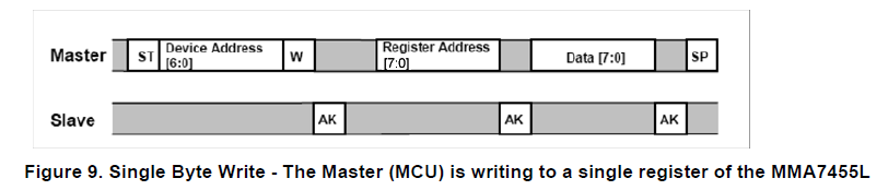
I'm having problems interfacing my TM4C MCU to a MMA 7455 accelerometer.

I continuelly receive the Arbitration Lost error.

Fist I just wanted to write to the 0x16 register of the accelerometer to set it't mode and only after that to receive data from it.

But I have issues sending data.

I check the MCS register and no sign of setting the run / start / end condition bits (0,1,2).

Also the MDR register is always empty.

I paste here the function to initialize the I2C Master and the function to write data from the master (MCU) to slave (MMA 7455).

Init Function:

void I2C_Accelerometer_Init(void)
{
	//Init PB2 as I2C_0 SCL and PB3 as I2C_0 SDA	
	SysCtlPeripheralEnable(SYSCTL_PERIPH_I2C0);		//The I2C0 peripheral must be enabled for use.
	SysCtlPeripheralEnable(SYSCTL_PERIPH_GPIOB);		//The GPIOB peripheral must be enabled for use.
	
	GPIOPinConfigure(GPIO_PB2_I2C0SCL);
	GPIOPinConfigure(GPIO_PB3_I2C0SDA);
	
	GPIOPinTypeI2CSCL(GPIO_PORTB_BASE, GPIO_PIN_2);
	GPIOPinTypeI2C(GPIO_PORTB_BASE, GPIO_PIN_3);
	
	GPIOPadConfigSet(GPIO_PORTB_BASE, GPIO_PIN_2, GPIO_STRENGTH_2MA,GPIO_PIN_TYPE_STD_WPU); //Configure PUR for PB2
	GPIOPadConfigSet(GPIO_PORTB_BASE, GPIO_PIN_3, GPIO_STRENGTH_2MA,GPIO_PIN_TYPE_OD); //Configure OD for PB3
	GPIODirModeSet(GPIO_PORTB_BASE, GPIO_PIN_2|GPIO_PIN_3, GPIO_DIR_MODE_HW);	   //Set direction by HW for PB2 and PB3

	I2CMasterInitExpClk(I2C0_BASE,SYS_clock_get,0);		//Set System clock and normal (100 kbps) transfer rate for I2C_0
}

I2C Write Function:

unsigned char I2C_Write(unsigned char Slave_Address, unsigned char Register_Address, unsigned char Register_Value)
{	
	unsigned char error_nr = 0;

	//Step 1. Set Slave address and Write mode (R/W bit = 0)
	I2CMasterSlaveAddrSet(I2C0_BASE,Slave_Address,Master_Tx_Slave_Rx);	//Set slave address and send mode
	
	//Step 2. Send the 8bit register address to write to
	I2CMasterDataPut(I2C0_BASE, Register_Address); //Send the register address to the Slave device	
	while(I2CMasterBusBusy(I2C0_BASE)){}
	
	I2CMasterControl(I2C0_BASE, I2C_MASTER_CMD_BURST_SEND_START);
	while(I2CMasterBusy(I2C0_BASE)){}
	
	error_nr = I2CMasterErr(I2C0_BASE);
	if(error_nr !=0)
	{
		if(error_nr ==0x10)
		{
			I2CMasterControl(I2C0_BASE, I2C_MASTER_CMD_BURST_SEND_ERROR_STOP);
		}
		return 0; //Error Service
	}
	else
	{
		//Step 3. Send data to write on register
		I2CMasterDataPut(I2C0_BASE, Register_Value);	//Send the register value to the Slave device
		I2CMasterControl(I2C0_BASE, I2C_MASTER_CMD_BURST_SEND_FINISH);
		while(I2CMasterBusy(I2C0_BASE)){}
		
		error_nr = I2CMasterErr(I2C0_BASE);
		if(error_nr !=0)
		{
			return 0;
		}
		return 1;
	}
}

So if you have any idea on what did I do wrong, please let me know.
I've been struggeling to find the issue for a few days already.

Thanks & Regards,

Alex


  • I'm thinking that you've "undone" the effect of your (proper):

    GPIOPinConfigure(GPIO_PB2_I2C0SCL);

    GPIOPinConfigure(GPIO_PB3_I2C0SDA);

    GPIOPinTypeI2CSCL(GPIO_PORTB_BASE, GPIO_PIN_2);

    GPIOPinTypeI2C(GPIO_PORTB_BASE, GPIO_PIN_3);

    with your (following) call to, "GPIODirModeSet()."

    Note that I2C does (always) require proper pull-up Rs - encamped upon SDA & SCL.

    Such test/troubleshooting always benefits from scope monitoring.   And - KISS dictates that you (start) w/a simple I2C EEPROM - rather than a (far) more complex device.

  • I think I already tried without the GPIODirModeSet API, anyway, will do again.

    However, would an external pull-up resistor be necessary for SCL? I just configured the internal one and connected the SCL pin to PB2 through a simple wire.

    In the MCU datasheet it is said that SDA should be configured as open-drain, so I assume no external resistor needed there.

    I'm interfacing the accelerometer since I need it to controll a robot that I'm working on.

    Regards,

    Alex

  • Gaal Alexandru said:
    In the MCU datasheet it is said that SDA should be configured as open-drain, so I assume no external resistor needed there.

    Upon what basis do you so assume?   Open-drain may pull-down - NOT pull-up - so very much an external pull-up R IS required.

    Both SDA & SCL "demand" pull-ups (of that there is NO doubt!)   Vendor's internal pull-ups are high in value - thus "round" signal edges - lower value (external) Rs always prove best.

    While you "need" that accelerator for your robot - its complexity (always) "Gets in the way."   Simpler device (EEProm) enables your systematic progress - few climb "Kilimanjaro" as (very) first climb.   KISS rules - even here.   (and especially, here)

  • I assumed on my faulty logic :)
    Will try with the external pull-ups, what Resistor would be more suitable?
  • 4K7 usually proves effective. If not available you may use 3 - 10K - all far out-perform vendor's (far too high) internal resistors.  (EZ to implement - not so much to "work" w/in real world)

    Do remove that GPIODirModeSet() call. You may wish to review the source code (it's fully provided) and see how it "spoils" your earlier I2C set-up... (and I'm uncertain about the PadConfig() - those appear "not in use" w/in vendor's Peripherals/Examples/I2C...)

  • I tried with the external pull-ups, the situation the situation is the following.
    I don't receive the ARBLST error, but I receive the DATACK and ADRACK errors.

    I tried to have the SDA just on open drain (w/o pull-up resistor) and the bus was kept busy for ever.
  • We've NO idea of the code your App (now) uses. That can't be good - can it.

    If you persist w/out pull-up R on SDA (we thought you had given up that (false) assumption) there is nothing (anyone) can do to assist...
  • Don't get me wrong, I didn't insist on not using pull-up resistor on SDA, just tried the behavior with and without (only for  my experience...)

    Anyway, I have the whole app (code) on githup at: https://github.com/gaalalexandru/droidbot, ... under modules\i2c_handler and accelerometer_handler folder is the code of interest... but I think it would be too much to ask someone to review it, since it's already quite large.

    But if you have spare time...please feel free.

    Just a short overview of the I2C startup in my code

    main calls SYS_startup

    SYS_startup calls Accelerometer_init

    Accelerometer_init calls I2C_Accelerometer_Init and then I2C_Write

  • If it's of any importance, I use KEIL and the mcu is TM4C123.
  • Don't get me wrong, I didn't insist on not using pull-up resistor on SDA, just tried the behavior with and without (only for  my experience...)

    The I2C bus does not work without pullup resistors, they are inherently required for functionality. Both lines (but especially SDA) are switchable between input and output, both on master and slave side, and (in the case of SCL and clock stretching) from more than one side as output. That only works with OD and pullup. When leaving SDA floating, the master can't pull it down, thus not generate a start condition, and thus returns busy till eternity...

    I strongly suggest a scope, to view the actual events on the bus. Is the slave returning an ACK upon addressing ? Is the address at all correct ?

    ... I didn't insist on ...

    BTW, "persist" means something different than "insist" ...

  • @f.m.,

    SO neat that even as "non-native" English speaker you've mastered the fine difference in word meaning - excellent my friend.

    Indeed - poster should visit the "other" I2C post in which both you & Robert have advised "against" I2C - suggesting SPI as a (most) valid substitute. BTW - your historical perspective on I2C is most informative - the efforts to "improve" upon the standard have "unleashed demons" - and those are (sure) to "persist."
  • I have a similar problem. I am connecting MPU-6050 accelerometer to the evaluation board EK-TM4C1294XL which uses TM4C1294NCPDTI chip via I2C. I am using 3.9k pull-up resistor connected to 3.3v on the booster pack pin on the evaluator board. When I run the following program, I am getting zero for the values. The slave address and the register addresses are correct. Previously I had connect the accelerometer to a freescale microcontroller and it worked with the slave and register addresses used here. Can you please tell me where the error is? I added the SysCtlDelay (1000) after reading one of the posts in this forum.

    #include <stdint.h>
    #include <stdbool.h>
    #include "inc/hw_ints.h"
    #include "inc/hw_memmap.h"
    #include "inc/hw_types.h"
    #include "driverlib/debug.h"
    #include "driverlib/fpu.h"
    #include "driverlib/gpio.h"
    #include "driverlib/interrupt.h"
    #include "driverlib/pin_map.h"
    #include "driverlib/rom.h"
    #include "driverlib/rom_map.h"
    #include "driverlib/sysctl.h"
    #include "driverlib/sysctl.c"
    #include "driverlib/timer.h"
    #include "driverlib/timer.c"
    #include "driverlib/uart.h"
    #include "driverlib/uart.c"
    #include "utils/uartstdio.h"
    #include "utils/uartstdio.c"
    #include "inc/hw_i2c.h"
    #include "driverlib/gpio.c"
    #include "driverlib/i2c.h"
    #include "driverlib/i2c.c"
    #include "driverlib/interrupt.c"
    #include "driverlib/cpu.c"
    #include "driverlib/cpu.h"

    //*****************************************************************************
    //
    //! In this program, the timer generates an interrupt every 5 seconds. When
    //! interrupted, I2C will receive data from slave.
    //!
    //! UART0, connected to the Virtual Serial Port and running at 115,200, 8-N-1,
    //! is used to display messages from this application.
    //
    //*****************************************************************************

    #define TIMER_INTERVAL 3 // 3 sec timer periodic interrupt
    #define SLAVE_ADDR 0x68 // address of slave unit
    #define AccelX 0x3B

    uint32_t g_ui32SysClock; // System clock rate in Hz.
    char val1; // accelerometer value

    //*****************************************************************************
    //
    // The error routine that is called if the driver library encounters an error.
    //
    //*****************************************************************************
    #ifdef DEBUG
    void __error__(char *pcFilename, uint32_t ui32Line)
    {
    }
    #endif

    //*****************************************************************************
    //
    // The interrupt handler for timer interrupt.
    //
    //*****************************************************************************
    void Timer0IntHandler(void)
    {
    TimerIntClear(TIMER0_BASE, TIMER_TIMA_TIMEOUT); // Clear timer interrupt.
    } // end Timer0IntHandler

    //*****************************************************************************
    //
    // Configure UART and its pins.
    //
    //*****************************************************************************
    void ConfigureUART(void)
    {
    SysCtlPeripheralEnable(SYSCTL_PERIPH_GPIOA); // Enable GPIO Peripheral used by UART.
    SysCtlPeripheralEnable(SYSCTL_PERIPH_UART0); // Enable UART0.
    GPIOPinConfigure(GPIO_PA0_U0RX); // Configure GPIO Pins for UART mode.
    GPIOPinConfigure(GPIO_PA1_U0TX);
    GPIOPinTypeUART(GPIO_PORTA_BASE, GPIO_PIN_0 | GPIO_PIN_1);
    UARTStdioConfig(0, 115200, g_ui32SysClock); // Initialize UART for console I/O.
    } // end ConfigureUART

    //*****************************************************************************
    //
    // Configure I2C for I2C7
    //
    //*****************************************************************************
    void ConfigureI2C(void)
    {
    SysCtlPeripheralEnable(SYSCTL_PERIPH_I2C7); // enable peripheral I2C7
    SysCtlPeripheralEnable(SYSCTL_PERIPH_GPIOD); // enable port connected to I2C7
    GPIOPinConfigure(GPIO_PD0_I2C7SCL); // Configure pin muxing for I2C7
    GPIOPinConfigure(GPIO_PD1_I2C7SDA);
    GPIOPinTypeI2CSCL(GPIO_PORTD_BASE,GPIO_PIN_0); // Select I2C function for these pins
    GPIOPinTypeI2C(GPIO_PORTD_BASE,GPIO_PIN_1); // for SDA
    I2CMasterInitExpClk(I2C7_BASE,g_ui32SysClock,false); // enable clocking of I2C7 with xmit speed of 100kbps
    } // end ConfigureI2C

    //*****************************************************************************
    //
    // initialize timer 0
    //
    //*****************************************************************************
    void InitTimer(void)
    {
    SysCtlPeripheralEnable(SYSCTL_PERIPH_TIMER0); // enable Timer0
    SysCtlPeripheralClockGating(true); // keep timer0 and UART running in sleep also
    SysCtlPeripheralSleepEnable(SYSCTL_PERIPH_TIMER0);
    SysCtlPeripheralSleepEnable(SYSCTL_PERIPH_UART0);
    IntMasterEnable(); // Enable processor interrupts
    TimerConfigure(TIMER0_BASE, TIMER_CFG_PERIODIC); // config timer
    TimerLoadSet(TIMER0_BASE, TIMER_A, g_ui32SysClock * TIMER_INTERVAL);
    IntEnable(INT_TIMER0A); // Setup the interrupts for the timer timeouts
    TimerIntEnable(TIMER0_BASE, TIMER_TIMA_TIMEOUT);
    TimerEnable(TIMER0_BASE, TIMER_A); // Enable timers
    } // end InitPortsTimer

    //*****************************************************************************
    //
    // Get accelerometer x_hi, x_low, y_hi, y_lo, z_hi, z_lo at address 0x3b through 0x40
    //
    //*****************************************************************************
    void GetADC_Data1()
    {
    I2CMasterSlaveAddrSet(I2C7_BASE,SLAVE_ADDR,false); // master to slave establish communication
    I2CMasterDataPut(I2C7_BASE,AccelX); // select x-accelerometer register in slave to read
    I2CMasterControl(I2C7_BASE,I2C_MASTER_CMD_BURST_SEND_START); // start and send
    SysCtlDelay(1000);
    while(I2CMasterBusy(I2C7_BASE)); // wait for MCU to finish transaction
    if (I2CMasterErr(I2C7_BASE)){
    UARTprintf("error");
    return;
    }

    I2CMasterSlaveAddrSet(I2C7_BASE,SLAVE_ADDR,true); // ready to receive Accelerometer x-axis data from slave
    I2CMasterControl(I2C7_BASE,I2C_MASTER_CMD_BURST_RECEIVE_START); // receive data
    SysCtlDelay(1000);
    while(I2CMasterBusy(I2C7_BASE)); // wait for MCU to finish transaction
    if (I2CMasterErr(I2C7_BASE)){
    UARTprintf("error");
    return;
    }
    val1 = I2CMasterDataGet(I2C7_BASE); // move Accelerometer x-axis high data to variable
    UARTprintf("X_Hi = %x,", val1);

    I2CMasterControl(I2C7_BASE,I2C_MASTER_CMD_BURST_RECEIVE_CONT); // receive data
    SysCtlDelay(1000);
    while(I2CMasterBusy(I2C7_BASE)); // wait for MCU to finish transaction
    if (I2CMasterErr(I2C7_BASE)){
    UARTprintf("error");
    return;
    }
    val1 = I2CMasterDataGet(I2C7_BASE); // move Accelerometer x-axis low data to variable
    UARTprintf("%x,", val1);

    I2CMasterControl(I2C7_BASE,I2C_MASTER_CMD_BURST_RECEIVE_CONT); // receive data
    SysCtlDelay(1000);
    while(I2CMasterBusy(I2C7_BASE)); // wait for MCU to finish transaction
    if (I2CMasterErr(I2C7_BASE)){
    UARTprintf("error");
    return;
    }
    val1 = I2CMasterDataGet(I2C7_BASE); // move Accelerometer y-axis high data to variable
    UARTprintf("%x,", val1);

    I2CMasterControl(I2C7_BASE,I2C_MASTER_CMD_BURST_RECEIVE_CONT); // receive data
    SysCtlDelay(1000);
    while(I2CMasterBusy(I2C7_BASE)); // wait for MCU to finish transaction
    if (I2CMasterErr(I2C7_BASE)){
    UARTprintf("error");
    return;
    }
    val1 = I2CMasterDataGet(I2C7_BASE); // move Accelerometer y-axis low data to variable
    UARTprintf("%x,", val1);

    I2CMasterControl(I2C7_BASE,I2C_MASTER_CMD_BURST_RECEIVE_CONT); // receive data
    SysCtlDelay(1000);
    while(I2CMasterBusy(I2C7_BASE)); // wait for MCU to finish transaction
    if (I2CMasterErr(I2C7_BASE)){
    UARTprintf("error");
    return;
    }
    val1 = I2CMasterDataGet(I2C7_BASE); // move Accelerometer z-axis high data to variable
    UARTprintf("%x,", val1);

    I2CMasterControl(I2C7_BASE,I2C_MASTER_CMD_BURST_RECEIVE_FINISH); // receive data
    SysCtlDelay(1000);
    while(I2CMasterBusy(I2C7_BASE)); // wait for MCU to finish transaction
    if (I2CMasterErr(I2C7_BASE)){
    UARTprintf("error");
    return;
    }
    val1 = I2CMasterDataGet(I2C7_BASE); // move Accelerometer z-axis low data to variable
    UARTprintf("%x\n", val1);
    } // end GetADC_Data

    //************************************************************************************
    //
    // When timer interrupt is generated, I2C pulls data from the slave and displays it.
    //
    //************************************************************************************
    int main(void)
    {
    g_ui32SysClock = MAP_SysCtlClockFreqSet((SYSCTL_XTAL_25MHZ | // clock running from crystal at 120MHz
    SYSCTL_OSC_MAIN |
    SYSCTL_USE_PLL |
    SYSCTL_CFG_VCO_480), 120000000);
    ConfigureUART(); // Initialize UART
    UARTprintf("Timer with sleep\n");
    ConfigureI2C(); // Initialize I2C for I2C7
    InitTimer(); // initialize timer
    //
    while(1)
    {
    SysCtlSleep(); // sleep till timer wakes up every 3 seconds
    GetADC_Data1(); // get accelerometer x,y,z values
    } // end while loop
    } // end main()
  • The slave address and the register addresses are correct.

    Have you checked the bus ? Does the slave return a NACK when addressed ?

    Previously I had connect the accelerometer to a freescale microcontroller and it worked with the slave and register addresses used here.

    Probably with example code from Freescale/NXP. Do the waveforms look similar,compared to the Freescale MCU ? Does it match the spec. ?

    I don't have a MMA7455, mainly used ST MEMS devices.

  • Hi,

    Does your project build up correctly, without any error? I don't think so. Hint: never ever #include .c file. Only .h file, while the .c file should be added at your project same way as the main file.

  • Does your project build up correctly, without any error? I don't think so. Hint: never ever #include .c file. Only .h file, while the .c file should be added at your project same way as the main file.

    Strongly support your point. While it could be made to compile, it is a mess.

    I generally refuse to look at such long, black/white "code deserts". They hurt the eyes, and creates me headaches. Hint: there is a nice code formatting tool available within this forum look for this [</>] icon ...

  • To Petrei, yes, the program compiled without error and am able to run it though the output is not what I expected. The reason the .c is in the include is because of compile error, I checked and included those libraries.
    To f.m. - No I have not checked the signal on the scope. Let me try that today.
  • The reason the .c is in the include is because of compile error, I checked and included those libraries.

    That is not a good way. There is most probably another issue with your project, perhaps you missed some include in a source file. Every module (*.c file) should build alone. The linker will finally put it together. I suggest a good C tutorial that covers the build and linking stages in detail.

    To understand why it's a bad idea, try to include the same source in another module of your project, and than re-build ...

  • Some updates:

    - I used physical resistor to pull up  SCL and SDA (~5k).

    - Configured SDA as Open Drain: GPIOPadConfigSet(GPIO_PORTB_BASE, GPIO_PIN_3, GPIO_STRENGTH_2MA,GPIO_PIN_TYPE_OD);

    - Deleted the GPIODirModeSet(GPIO_PORTB_BASE, GPIO_PIN_2|GPIO_PIN_3, GPIO_DIR_MODE_HW); 

    - Deleted also internal pull up configurations: GPIOPadConfigSet(GPIO_PORTB_BASE, GPIO_PIN_2, GPIO_STRENGTH_2MA,GPIO_PIN_TYPE_STD_WPU);

    When I check with the debugger the I2C0, still the following issues persist :)

    - Bus busy is set (I2C_MCS_BUSBSY bit)

    - Data is not sent (I2C_MDR_DATA is 0 all the time)

    - From the I2CMasterErr I keep receiving 0x0C (I2C_MASTER_ERR_ADDR_ACK and I2C_MASTER_ERR_DATA_ACK)

    I post again the init function:

    void I2C_Accelerometer_Init(void)
    {
    	//Init PB2 as I2C_0 SCL
    	//Init PB3 as I2C_0 SDA	
    	SysCtlPeripheralEnable(SYSCTL_PERIPH_I2C0);		//The I2C0 peripheral must be enabled for use.
    	SysCtlPeripheralEnable(SYSCTL_PERIPH_GPIOB);		//The GPIOB peripheral must be enabled for use.
    	
    	GPIOPinConfigure(GPIO_PB2_I2C0SCL);
    	GPIOPinConfigure(GPIO_PB3_I2C0SDA);
    	GPIOPinTypeI2CSCL(GPIO_PORTB_BASE, GPIO_PIN_2);
    	GPIOPinTypeI2C(GPIO_PORTB_BASE, GPIO_PIN_3);
    	//GPIOPadConfigSet(GPIO_PORTB_BASE, GPIO_PIN_2, GPIO_STRENGTH_2MA,GPIO_PIN_TYPE_STD_WPU); //Configure PUR for PB2
    	GPIOPadConfigSet(GPIO_PORTB_BASE, GPIO_PIN_3, GPIO_STRENGTH_2MA,GPIO_PIN_TYPE_OD);        //Configure OD for PB3
    	//GPIODirModeSet(GPIO_PORTB_BASE, GPIO_PIN_2|GPIO_PIN_3, GPIO_DIR_MODE_HW);	          //Set direction by HW for PB2 and PB3
    
    	I2CMasterInitExpClk(I2C0_BASE,SYS_clock_get,0);		  //Set System clock and normal (100 kbps) transfer rate for I2C_0
    }

    and the write function:

    unsigned char I2C_Write(unsigned char Slave_Address, unsigned char Register_Address, unsigned char Register_Write_Value)
    {	
    	unsigned char error_nr = 0;
    	//Step 1. Set Slave adress and Write mode (R/W bit = 0)
    	I2CMasterSlaveAddrSet(I2C0_BASE,Slave_Address,Master_Tx_Slave_Rx);	//Set slave address and send mode
    	
    	//Step 2. Send the 8bit register adress to write to
    	I2CMasterDataPut(I2C0_BASE, Register_Address); //Send the register adress to the Slave device
    	//while(I2CMasterBusBusy(I2C0_BASE)){}
    	
    	I2CMasterControl(I2C0_BASE, I2C_MASTER_CMD_BURST_SEND_START);
    	while(I2CMasterBusy(I2C0_BASE)){}
    		
    	error_nr = I2CMasterErr(I2C0_BASE);
    	if(error_nr !=0)
    	{
    		if(error_nr ==0x10)
    		{
    			I2CMasterControl(I2C0_BASE, I2C_MASTER_CMD_BURST_SEND_ERROR_STOP);
    		}
    		return 0;
    	}
    	else
    	{
    		//Step 3. Send data to write on register
    		I2CMasterDataPut(I2C0_BASE, Register_Write_Value);	//Send the register value to the Slave device
    		I2CMasterControl(I2C0_BASE, I2C_MASTER_CMD_BURST_SEND_FINISH);
    		while(I2CMasterBusy(I2C0_BASE)){}
    			
    		error_nr = I2CMasterErr(I2C0_BASE);
    		if(error_nr !=0)
    		{
    			return 0;
    		}
    		else
    		{
    			return 1;
    		}
    	}
    }

    Unfortunatly I don't have acces to an scope to see exactly what's hapening on the pins.

    And yes, the slave adress is correct (0x1D), also is it's register that I'm trying to write to (0x16).

  • As (I think) stated earlier, I exercised similar projects with other MCUs and other I2C slaves, so my code insight is rather limited.

    Unfortunatly I don't have acces to an scope to see exactly what's hapening on the pins.

    A logic analyzer would probably do as well. You can get expedient one's for quite affordable prices - below the "magic" 100 USD/EUR limit.

    And yes, the slave adress is correct (0x1D), also is it's register that I'm trying to write to (0x16).

    Specs are often confusing here - does this address need a shift to accommodate for the R/W bit, or not ?

    - From the I2CMasterErr I keep receiving 0x0C (I2C_MASTER_ERR_ADDR_ACK and I2C_MASTER_ERR_DATA_ACK)

    This would suggest an address issue. But without scope/logic analyzer, you are more or less limited to trial-and-error ...

  • f. m. said:
    does this address need a shift to accommodate for the R/W bit, or not ?

    Could you detail this?

    Are you referring to, how the slave handles write commands?

    I will quote from the MMA7455 datasheet:

    To start a write command, the Master transmits a start condition (ST) to the MMA7455L, slave address ($1D) with the R/W bit set
    to “0” for a write, the MMA7455L sends an acknowledgement. Then the Master (MCU) transmits the 8-bit address of the register
    to write to, and the MMA7455L sends an acknowledgement. Then the Master (or MCU) transmits the 8-bit data to write to the
    designated register and the MMA7455L sends an acknowledgement that it has received the data. Since this transmission is complete,
    the Master transmits a stop condition (SP) to the data transfer. The data sent to the MMA7455L is now stored in the appropriate register.

    And the sequence from my MCU's datasheet:

  • Could you detail this?

    Having read datasheets of different I2C slaves, the addressing seems not consistent. As you know (I hope), the LSB of the address is reserved to differ between read access and write access. Thus, each device actually occupies two addresses (from a "bus" point of view).

    Often, I2C peripherals in MCUs explicitly specify a "7 Bit I2C address". This implies a shift (1 bit left) and automatic setting of the R/W bit, depending on the access mode (read or write).

    Now, how does the slave spec. handle this address (0x1D) ? Does this value include the R/W bit, or not ? If you read "7 bit address" anywhere in the spec., it most probably implies a left-shift. And since the value 0x1D has the LSB set, I guess it <is> a 7-bit address ...

  • I'm not sure about this.

    Yes, it's a 7 bit address, but the 8th bit in the slaves register is the SPI / I2C enable bit.

    As I see in the TivaWare I2C API, the I2CMasterSlaveAddrSet functions already shifts the slave adress to the left by one. 
    HWREG(ui32Base + I2C_O_MSA) = (ui8SlaveAddr << 1) | bReceive;

    On my MCU, indeed the register for the slave adress also contains on bit 0 the read / transmit bit, but on the slave register not... I don't know how this is / could be handled.

    Could it be possible that the two devices are incompatible?

  • Could it be possible that the two devices are incompatible?

    I don't think so. Both seem to specify/handle the address in the same way. The only (and confusing) thing is - when you watch and decode the address bit transfer, you read 0x3A (or 0x3B) on the bus, i.e. left-shifted by one bit. But you don't have a scope/analyzer yet, so no danger ... ;-)

    As said, I've not yet exercised this on a TM4C device. But I think there is something missing. Looking at the MM7455 datasheet, "single byte read", there is a repeated start condition ("SR") required between the register-write and the actual read. My knowledge of the TivaWare lib is very limited, but I haven't noticed something like this in your code.

    A scope/analyzer pays off over time ...

  • Ok, just placed the order for an USB logic analyser :-)
  • In the meantime, I suggest to check if the "repeated start" condition is missing.
    After writing the register address, a "repeated start should follow, than the device address again, and then the actual read.
    When running in the debugger , it should IMHO be possible to stop after the register write, and use a voltmeter to check for the stop condition.
    Most I2C devices are static designs, and don't have a time limit for such conditions.

    How to achieve a "repeated start" I would leave it to the TivaWare experts.
    According to the TM4C datasheet, you just need to transmit a "start condition" again, without preceding stop.