This thread has been locked.

If you have a related question, please click the "Ask a related question" button in the top right corner. The newly created question will be automatically linked to this question.

PWM gens ignore PWMnCMPB value change in PWM sync updates.

Guru 55913 points
Other Parts Discussed in Thread: LM3S8971, TM4C1294NCPDT

MCU = TM4C1294NCPDTi3

Conditions: (3 Phase PWM motor drive)

1. PWM GEN mode up/down count, Gen mode Sync, Gen mode Sync global and or Gen mode DB sync global or local.

2. PWM GEN0 Raw interrupt load count zero for processing GEN sync updates, 3 time base synched PWM generators.  

3. PWMnDBRISE/FALL register values = 1,2,3,4,5, 6 etc...

A. If ever PWMnCMPA/B register values are set extremely low say (1-42) an immediate dead lock occurs in new values (above) the previous value set in PWMnCMPB furthermore being ignored and or counted during synchronous updates. That results in the pulse width of PWM0 pwmB not being constrained in monotonic counts matching the compare values of PWMnCMPB, suspecting only during (down) counts. That results in numerous missing edge times in the down counts of would be matches CMPB that remain ignored.

B. if ever PWMnCMPA/B values are initially set higher say 600 the same basic condition CMPB described above occurs during synchronous updates. However only up to the value previously loaded seemingly while counting down and loading any higher values CMPB are ignored by the PWM generator. Thus results in missing edge times pwmB and the wave form produced in the bridge is missing artifacts.

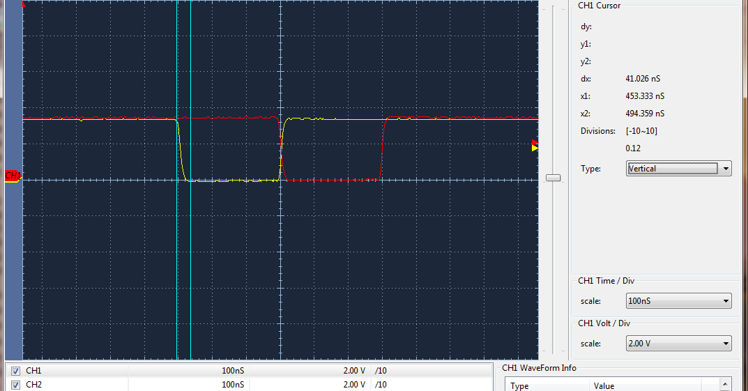
Provided register monitors recording differences CMPB in two different load values and resulting wave form (captures). That is the only way to detect the load count value failure since CCS debug shows CMPA/B register values being equal during the synchronous updates. The outcome of ignoring matches CMPB are missing edges in the pulse width changes made during synchronous update. 

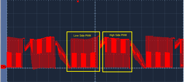
Newly discovered below scope capture Trapezoidal wave forms (produce) low side PWM when CMPB is not being (completely) ignored. Fast decay then produces in Full Bridge low side PWM when setting a starting pulse width CMPB below 100% duty cycle. That Is an indication CMPB becomes (jammed) when set nearly 100% duty and refuses to then process rising duty cycle values during synchronous updates of all 3 PWM generators. 

Why are CMPB down count changes being ignored in synchronous updates after 100% duty cycle is set in all 3 generators?

Notice low side PWM now works when Stellaris (team engineers) failed, releasing SW public domain (claiming) low side PWM in RDK user manual! That falsified claim (low side PWM fast decay mode) mislead all growing engineers down a black hole of singularity.

  • Keeping analysis on point using registers and wave forms seems appropriate. CMPB is also instigating FED issues making for odd pwmB dead band generator handling being required to compensate for this update failure. Notice the capture wave from below PWM2 and the values CMPA increments dynamic (15-960) both watches. Notice CMPB static (42) is updated dynamically from (42-960) yet the pulse width (capture) CMPB remains set at (42). 

    CMPA seems unaffected, (CMPB fails updating). However both CMPA/B receive load value changes and synchronous updates together. The PWM2DBCTL enable bit is toggled (after) CMPB produces high pin states only in past events of the last cycle during any new cycle.   

    Register watch: The resulting duty cycles pulse width (scope capture) is not keeping proportion nor reflective updates to PWMnCMPB.

    Why would CMPA pulse width update flawlessly and CMPB pulse width not ???

    OTF: on the fly

  • It seems to me the reason why dead band generator pwmB is behaving poorly is mainly due to CMPB load value changes made during the synchronous update function are being ignored.

    We are forced to clear and set PWMnDBCTRL enable each cycle as a WA compensating for PWMnCMPB update failure.

    Setting PWMENUPDT REG 28 for various levels of update priority makes no difference in the resulting wave form.

    /* Set the PWM output control block pin state for the update mode */
    ROM_PWMOutputUpdateMode(PWM0_BASE, (PWM_OUT_2_BIT | PWM_OUT_3_BIT | PWM_OUT_4_BIT |
                                        PWM_OUT_5_BIT | PWM_OUT_6_BIT | PWM_OUT_7_BIT) ,
           PWM_OUTPUT_MODE_SYNC_LOCAL);

    Technically it should not be necessary patching or WA compensating for PWMnCMPB update failure of pwmB dead band generator. It is perceived as failure in this post technically due to the way dead band has been functionally described in data sheet and HW is not actually complying with that circuit analysis.

    08-9-2016: Patch (not shown) duty cycle update (initially) setting CMPB below 98% pulse width (seemingly) removes need for patch below and leaving Dead Band enabled 100% (seemingly) possible. Or is it ?,,, the only noticeable difference is the  FED/RED edge times are no longer present in wave forms pwmA/B. That seems to infer the dead band delay counters are not actually delaying pwmB FED relative to the pulse width of pwmA RED when PWMnDBCTRL bit (left) enabled during local or global generator synchronous updates.

    Furthermore (PWM_GEN_MODE_DB_SYNC_GLOBAL or LOCAL) seemingly has no direct ability to control each dead band generators (update) pulse width  pwmB and seems a useless control. Here again PWM peripheral Hardware dead band generation is not behaving as described in datasheet and CMPB then seems to tie into that failure. Patch is placed in the pulse width synchronous update function.  

        ulPWMEnable = HWREG(PWM0_BASE + PWM_O_ENABLE);
    	/* Is High side phase A inactive, clear dead bands */
    	if((ulPWMEnable & 0x4) == 0)
    	{
    		/* Clear dead band, pass PWM0 pwmA/B through dead band gens. */
    		HWREG(PWM0_BASE + PWM_GEN_1 + PWM_O_X_DBCTL) &= ~(PWM_X_DBCTL_ENABLE);
    	}
    	else
    	{
    		HWREG(PWM0_BASE + PWM_GEN_1 + PWM_O_X_DBCTL) |= PWM_X_DBCTL_ENABLE;
    	}
    	/* Is High side phase B inactive, clear dead bands */
    	if((ulPWMEnable & 0x10) == 0)
    	{
    		/* Clear dead band, pass PWM0 pwmA/B through dead band gens. */
    		HWREG(PWM0_BASE + PWM_GEN_2 + PWM_O_X_DBCTL) &= ~(PWM_X_DBCTL_ENABLE);
    	}
    	else
    	{
    		HWREG(PWM0_BASE + PWM_GEN_2 + PWM_O_X_DBCTL) |= PWM_X_DBCTL_ENABLE;
    	}
    	/* Is High side phase C inactive, clear dead bands */
    	if((ulPWMEnable & 0x40) == 0)
    	{
    		/* Clear dead band, pass PWM0 pwmA/B through dead band gens. */
    		HWREG(PWM0_BASE + PWM_GEN_3 + PWM_O_X_DBCTL) &= ~(PWM_X_DBCTL_ENABLE);
    	}
    	else
    	{
    		HWREG(PWM0_BASE + PWM_GEN_3 + PWM_O_X_DBCTL) |= PWM_X_DBCTL_ENABLE;
    	}  
  • Appears that No one at TI is aware of this issue and perhaps list a PWM peripheral anomaly alert. One less attractive WA is to Not set the pulse width CMPB (15) near 100% for any reason if you ever want to reduce duty % of later generator synchronous update cycles. The PWM generator does not care if you load CMPB value 0x0 after 100% (15) duty, it refuses to use (ANY) update load value after 100% duty was set. That seems to be some kind of undocumented errata the Stellaris team simply skirted over. CMPA starts out at 20% duty cycle as CMPB pulse width is being sync updated near 100% in zero interrupt handler. Seemingly causes timer dead locks of CMPB at opposite ends of PWM timers ability in Up/DN count mode.

    The alternative is to subtract the minimum pulse width from the period and arrive at a lower CMPB value below 100% roughly 85% in the 1st synch generator update. That sets CMPB/A to near Equal values as CMPA duty moves 20%-85%. A mixture of high/low side PWM (fast decay) results minimum pulse width set above 0.8us and leans more high side PWM (slow decay) when below 0.8us. The latter 85% CMPA/B creates radial alignment (Cats Eyes) 50% crossings pwmA/B with dead band pwmA RED attached (horizontal bars 40ns). Discovered missing is FED never present in pwmB seems is pass through mode when pwmA is dead banding but the resulting pulse width pwmB is much smaller than pwmA. That seems to indicate dead band generator pwmB is truncating the original pulse width derived from pwmA and again pwmB pass through is short lived. 

    CH1=pwmA, CH2=pwmB

    Notice FET body diode (dv/dt) CH2 seems to double clamp (ringing) and both high and low side PWM drives have (dv/dt) artifacts in the low/high PWM.  CH1 is low side pwmB drive 0.8us.

  • BP101 said:
    Why would CMPA pulse width update flawlessly and CMPB pulse width not ???

    Might that be - quite simply - the nature of the "Deadband" beast?

    Now I've produced & presented multiple, hi-res, scope caps - displaying PWM_A & PWM_B operating under conditions of: No Deadband, slight Deadband & substantial Deadband.   And - when Deadband is enabled - PWM_B "loses its independent nature - becomes "locked" to PWM_A's output - but for being inverted - and w/the intrusion of deadband - which provides, "Safe Timing Zones" (preventing the overlap of PWM_A & PWM_B) upon both leading & trailing edges.

    When "Deadband" is enabled - even deadband w/zero parameters - it is my belief (thru experiment & observation) that PWM_B is not intended to be subject to (direct) pulse width updates.   Again (many times - now repeated) PWM_B - when under deadband - appears as the inversion of PWM_A with the addition of deadband guards upon leading & trailing edges...   Any/all expectations - beyond what's presented herein - are uniquely yours.  

  • Albeit even if dead band is cleared (watches/captures) reveal during synchronous updates CMPB remains locked near 100% duty cycle. Took some time to put it all together that pwmA pulse width being many times wider than pwmB actually indicates a dead lock occurred in all 3 PWM counters.

    The issues of near 100% duty CMPB jams PWM counter seems unrelated to dead band documented behavior. Fact is the dead band generator should invert pwmA pulse width to create an inverted pwmB pulse width and drop PWM0 pwmB only during dead band enables.

    That fact infers both pwmA and pwmB would indeed have (equal) pulse widths as scope capture reveals cats eye CMPA/B alignments. That results by not jamming CMPB near 100% duty where the underlying counter then refuses to assert any further updates up to that pulse width window.
     
    Seems the Stellaris team of engineers tried to pull one over on the community. The latter seems to be what occurred but they forgot to remove the written evidence trail in that haste.

  • Should not the record reveal that vendor's: Amit and Chuck,  along w/ posters Robert & cb1 - have each - separately & independently - requested that you provide the shortest code listing (demonstrating your belief/quandry) - so that (some) peer review may occur?

    Your description of the issue has proven - and continues - to be most difficult to grasp.   You've been posting this topic/related for months now - and only the (bravest or most "misguided") respond.

    Again - my past posts (which included detailed, PWM scope caps) revealed PWM_B performing EXACTLY to specification - with and without deadband - and never/ever evidencing ANY attempt to, "Pull one over on the community!"   Such "pull" may (now) be occurring - but the source is NOT this vendor...

  • Your continued argument for need of posting code holds no weight in lue of provided register monitors. Posted monitors and wave forms each proving later synchronous update value changes CMPB being completely ignored if or when pwmB duty cycle is at some point (stressed) near 100%.

    It is not a SW anomaly causing CMPB jamming, it is PWM peripheral HW failure in asserting the commands of SW control. Especially true in lue of vendors failure to document an errata warning explaining CMPB 100% duty jamming behavior in both LM3S8971 and TM4C1294NCPDT. The motor ware RDK was the vendors baby and how it was crying for mothers milk.

    Alternatively the WA signal wave forms posted proving that evidence of WA to remove the CMPB jam condition stated through out this post. Other earlier posts reporting farther down the tool chain pwmB dead band was behaving oddly in light of later find 100% duty jamming CMPB.

    Again it is the vendors Stellaris team that carelessly released this debacle onto the community (qs-bldc / qs-basic).  Both version SW leaving dead band (cleared) state 100% of the time was not proper 3 phase commutation HW configuration. Stellaris team directly took advantage of HW anomaly jamming CMPB at 100% duty subtracting the dead band parameter value from the period forming a CLOAKED delay period leaving the low side MOSFETS driving at near 100% duty cycle modulated by only pwmA duty cycle updates. That is just nuts to be kind!

  • BP101 said:
    "Your"... argument for need of posting code holds no weight in lue of

    It is not "just" my request for "Minimal Code" - it IS the (repeated) request of vendor's Amit, Chuck & poster Robert.   Note all have tried to assist - and are most competent & experienced - yet have no chance due to your post's technical imprecision & introduction of opinion.   

    Is it not better to attempt to SELL your post - to engage high quality response?   Can your (undocumented) opinion - and attack upon this vendor - in any way prove effective?

    A better way to present your case has been presented - repeatedly.  It is very much "w/in the realm" that (something) you've added to vendor's original RDK code has caused or contributed to your "issue."   Your refusal to follow "SOP" (shortest code listing which conclusively exhibits your "find") cannot be justified...

    As your presentation descends - so too your word use.  (again)   (there is NO "lue" - lieu is what was intended.)   Might such, "lack of attention to detail" (or disregard) similarly aid/abet your MCU's (reported) miscue condition?

  • This post is not an attack against vendor though certain past Stellaris team members very provable acts have caused mayhem up the tool chain, intentional or not.

    Could it be more that CB1 has no desire to hear truth instead holds fast to incorrect long held beliefs Fast Decay has no low side PWM pulses? 

    Again PWM0 pwmA adjusts to the specified duty cycle when pwmB does not during synchronous updates, Watch cases. That directly PROVES case HW is at fault when setting near 100% duty cycle, not SW. Again that is proven with dead band (cleared) pointing directly to ePWM peripheral having timing issues or some other anomaly. The Vendor should take a look at this and update the errata document especially since it Bamboozled even the Stellaris team. Yes they were also fooled, otherwise it would be a deliberate attempt of the vendor to defraud the public and we know that is not the case. 

    It is expected the vendor would start taking this point and case a bit more seriously especially since (fast decay) had never worked in the SW released into public domain. Slow decay mode was consistently asserting even if user was selecting fast decay PWM switching. Who would know the difference since most public domain Trapezoidal wave forms captured revealed in datasheets etc.. represent high side PWM never to show the results of low side PWM. 

  • Patch above proves necessary to even see a dead band delay added and present in the captured wave forms minimum pulse width pwmA. Adding a patch few posts up forces CMPB to be updated by disabling dead band both PWM generators decoupling CMPA/B from both dead band generators. That move seemingly becomes counter intuitive to configuring (PWM_GEN_MODE_DB_SYNC_LOCAL or GLOBAL). Like wise PWMnCMPB is not decoupling from dead band generator pwmB upon clearing PWMnDBCTRL bit. Yet PWMnCMPA decouples every time without any issues when clearing PWMnDBCTRL bit.

    Leaving dead band generators fully enabled during synchronous updates directly effects (pwmA pulse width) not being filtered down order to form pwmB pulse width as data sheet section 23.3.5 elaborates it should do by design.  In effect it appears as if CMPB for some reason simply ignores the embedded SW command to change pulse width as instructed in synchronous updates. In hind sight of past and expert Stellaris team failure to properly implement PWMnCMPB updates (subject of qs-bldc), vendor must concede HW is causing embedded SW failures as is quite provable in several ways put forth explained in detail this forum in last months.

    Otherwise it would not be necessary at any time to ever disable (specific) dead band generators prior to individual sync updates in order to update PWMnCMPB. This is a vendor lab issue not related to embedded SW patch posted above that only attempts to correct a systemic HW failure in the Stellaris PWM peripherals topology. This failure makes it appear in scope captures as if CMPB is jammed and not passing the pulse width pwmA onto dead band pwmB that data sheet 23.3.5 states originates and emanates from PWMnCMPA. Again pwmB pulse width is a STATIC inversion of pwmA being delayed by or added to the period there of PWMnDB-RISE/FALL register values.

    CH1-pwmB, CH2-pwmA. Top/bottom captures CH2 indicate 120ns RED and not unexpected pwmB drops FED entirely (CH2 bottom capture) during minimum pulse width sync updates.