


Hello
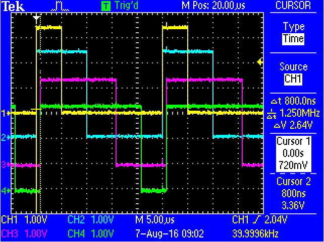
The starting point is the output 800ns Delay generated the PWM between Gen0 and Gen 1.
How do I generate the same output ?
thanks.
Ch1(Gen0_PWM0), Ch2(Gen0_PWM1), Ch3(Gen1_PWM2), Ch4(Gen1_PWM3),
int
main(void)
{
    //
    // Enable lazy stacking for interrupt handlers.  This allows floating-point
    // instructions to be used within interrupt handlers, but at the expense of
    // extra stack usage.
    //
    ROM_FPULazyStackingEnable();

    //
    // Set the clocking to run directly from the crystal.
    //
    ROM_SysCtlClockSet(SYSCTL_SYSDIV_1 | SYSCTL_USE_OSC | SYSCTL_OSC_MAIN |
                       SYSCTL_XTAL_16MHZ);


    // Initialize the UART and write status.
			ConfigureUART();

		// PWM Clock set
				ROM_SysCtlPWMClockSet(SYSCTL_PERIPH_PWM0);

		//  PWM0 Peripheral Enable
				ROM_SysCtlPeripheralEnable(SYSCTL_PERIPH_PWM0);

    //PWM Corresponding GPIO Port Enable
				ROM_SysCtlPeripheralEnable(SYSCTL_PERIPH_GPIOH);

    //GPIO Anternate Function.
				GPIOPinConfigure(GPIO_PH0_M0PWM0);
				GPIOPinConfigure(GPIO_PH1_M0PWM1);
				GPIOPinConfigure(GPIO_PH2_M0PWM2);
				GPIOPinConfigure(GPIO_PH3_M0PWM3);

		// Configuration Pin  for use by the PWM peripheral
				GPIOPinTypePWM(GPIO_PORTH_BASE, GPIO_PIN_0 | GPIO_PIN_1|GPIO_PIN_2|GPIO_PIN_3);


	// PWM Gen Configure Set,   8 config mode
	// 1. Counting mode, 2, counter load &  comparator update sync mode, 3. debug behavior
	//	4. update synchronization mode for generator counting mode changes, 5. deadband parameter synchronization mode
	// 6.whether fault conditions are latched or not , 7. whether minimum fault period support is required,
	// 8. whether extended fault source selection support is enabled or not

				PWMGenConfigure(PWM0_BASE, PWM_GEN_0, PWM_GEN_MODE_DOWN | PWM_GEN_MODE_NO_SYNC);
				PWMGenConfigure(PWM0_BASE, PWM_GEN_1, PWM_GEN_MODE_DOWN | PWM_GEN_MODE_NO_SYNC);

			// Sets the period of a PWM generator (1 Pulse)  , PWM generator  [PWM_GEN_0 ~ 3]
			// 1/16,000,000 Hz =  62.5E-9 (1 pluse period time 62.5nS),
			// Osclilloscope measure  1 pulse Period 25uS  ,
			// 62.5nS  : 1 pluse  = x(period) : 400 pluse   =    (62.5nS X 400 Plus) = 25uS

				PWMGenPeriodSet(PWM0_BASE, PWM_GEN_0, 400);
				PWMGenPeriodSet(PWM0_BASE, PWM_GEN_1, 400);


			//Set the pulse width of PWM0  duty cycle. , ui32PWMOut : PWM_OUT_0, ~7

		// PWM0 (20%)   25uS x 0.2 = 5uS
				PWMPulseWidthSet(PWM0_BASE, PWM_OUT_0, 80);

		// PWM1 (40%)  25uS x 0.4 = 10uS
				PWMPulseWidthSet(PWM0_BASE, PWM_OUT_1, 160);

		// PWM2 (60%)  25uS x 0.6 = 15uS
				PWMPulseWidthSet(PWM0_BASE, PWM_OUT_2, 240);

		// PWM3 (80%)	25uS x 0.8 = 20uS
				PWMPulseWidthSet(PWM0_BASE, PWM_OUT_3, 320);

			// Start the timers in generator 0.  Enable the timer/counter for a PWM generator block [ PWM_GEN_0 ~3]
				PWMGenEnable(PWM0_BASE, PWM_GEN_0);
				PWMGenEnable(PWM0_BASE, PWM_GEN_1);

			// Enable the outputs.
			//ui32PWMOutBits : ( PWM_OUT_0_BIT  ~ PWM_OUT_7_BIT)   bEnable :  signal is enabled or disabled.
				PWMOutputState(PWM0_BASE, (PWM_OUT_0_BIT | PWM_OUT_1_BIT), true);
				PWMOutputState(PWM0_BASE, (PWM_OUT_2_BIT | PWM_OUT_3_BIT), true);

				UARTprintf(" PWM Out  , GPIO :  PH0(Gen0_PWM0) / PH1(Gen0_PWM1)/PH2(Gen1_PWM2)/PH3(Gen1_PWM3)\n");


				ROM_IntMasterEnable();
				ROM_PWMIntEnable(PWM0_BASE,PWM_INT_GEN_0);
				ROM_PWMIntEnable(PWM0_BASE,PWM_INT_GEN_1);


    //
    // Loop forever while the timers run.
    //
    while(1)
    {
    }
}


