This thread has been locked.

If you have a related question, please click the "Ask a related question" button in the top right corner. The newly created question will be automatically linked to this question.

Is it possible odd monotonic order PWMnCMPx match values cause comparator jamming?

Guru 55913 points
Other Parts Discussed in Thread: DRV8305, TM4C1294NCPDT

TM4C1294NCPDTi3

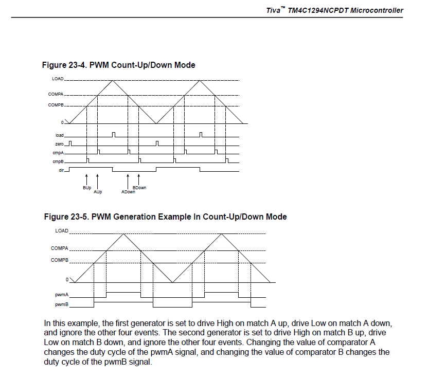
Is it possible if the PWM modules generators duty cycles or pulse width (if different values) are not staggered in descending monotonic order (Fig 23-5) PWMnCMPB might ignore synchronous updates of this register?

Notice datasheet 23-5 suggest center aligned overlapping signals and illustrates CMPB has roughly 20% more duty cycle than CMPA.

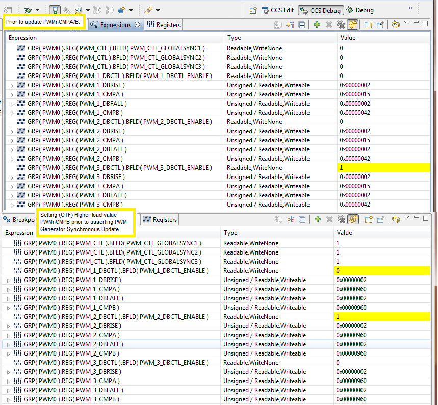
What happens if CMPB match value is higher than CMPA match value and how does that monotonic reversal affect dead band generators performance?

  • BP101 said:
    Is it possible if the PWM modules generators duty cycles...

    Bravo - the door (now) opens - possibly admitting the fact that individual coding sequences - and/or functions - (may) explain the difficulties you've (oft) reported.  

    I do not believe that the example (23-5) imposes ANY (at all) "linkages" between PWM_A & PWM_B.  Instead - as my past scope-caps prove - it is, "When and only when" - Deadband is Enabled/Imposed  - that any such linkages occur.  Further - that 20% "difference" you note - is purely (and entirely) the result of deadband parameters - active only when deadband is enabled.   There is NO/ZERO such "20%" "PWM difference" - established via design.

    What myself - and others suspect - is that (somehow) you've missed the fact that PWM_B (fully) loses its independent duty cycle control - upon the simple enabling of deadband.  (even when (both) deadband parameters are set to zero.)  Instead - again as my multiple (past) scope-caps reveal/confirm - the imposition of deadband forces PWM_B into an "Inverted form" of PWM_A - yet w/the presence of (parameter dictated) deadband (guardbands) upon PWM_B's (leading & trailing) edges.

    Thus - whenever PWM_A is logic high - PWM_B must be logic low.   And if deadband parameters are non-zero - dual guardbands will "bracket" PWM_B's leading and trailing edges.

    As many here have long suspected - it is likely that your methods and/or sequencing of  deadband functions - have caused (or at least been major contributors) to your reported issues.  

    Such explains why MANY here have requested your presentation of the shortest code block - which causes/confirms your issue - so that your peers may fully/properly (and maybe) duplicate your findings...   Or not...  

    Note: there are many possible code sequences - it may just be that the "one" you've chosen - has caused you such distress - and the opportunity to enlist the aid & support of multiple others - should (many believe) receive your full & prompt attention...

  • cb1- said:
    Further - that 20% "difference" you note - is purely (and entirely) the result of deadband parameters - active only when deadband is enabled

    As the author of the above writing - I plead "temporary insanity" - and note that "shock treatment" (legal, my state) "may" have worked.

    What I intended to write was that the difference between, "duty cycles" (PWM_A vs. PWM_B) as illustrated w/in 23-5 - resulted entirely from the different duty cycle values - programmed into that pair.  (PWM_A & PWM_B)   I would wager a large (even huge) sum - that even two identical such duty cycles may be programmed into that pair - and that identical and overlapping pulse outputs would result!

    Again - PWM_B is an entirely "independent, PWM operator" and becomes "bound/linked" to PWM_A - only when "Deadband is enabled."   That 20% difference in duty cycle - which you noted - is due ENTIRELY to the "duty cycle" values programmed into PWM_A & PWM_B.   There is absolutely NO/ZERO ~20% (offset) or deviation which exists by deliberate MCU design!

    When the deadband becomes enabled - and "large" parameter values exist - PWM_B "loses its independent duty cycle capability" instead becoming the "inversion of PWM_A - and differing from a "pure" inversion by the magnitude of the 2 (leading/trailing) deadband parameters.

  • > There is absolutely NO/ZERO ~20% (offset) or deviation which exists by deliberate design!

    Agree but that was not the point being elaborated in the post and of course overlapping exact matches CMPA/B are acceptable legal values.

    1. Again the post meant to suggest (what if) PWMnCMPB pulse width is ever made even 20% less relative to PWMnCMPA pulse width. 

    2. The monotonic matching (slope) comparators are expecting is reversed to that of a single timers increment (value) up counts, decrement (value) down counts.  

    3. No matter if dead band is even disabled; the trigger edge order signals passing through dead band are reversed to those being illustrated, text elaborated. The text suggest pwmA is used to invert, form pwmB but that behavior changes in light of enabling dead band in a reversal to the last CMPB match triggered edge. That results in dead band generator pwmB not asserting an edge delay into the pulse width pwmA and or preempting the signal passing it through untouched.

    4. PWM generators counters should not simply (stop responding) to synchronous updates of PWMnCMPB and that is occurring with logical order and good reason. Inferring the reversal of pulse widths PWMnCMPA and causing edge match jams PWMnCMPB.

  • BP101 said:
    PWM generators counters should not simply (stop responding) to synchronous updates of PWMnCMPB

    They should if deadband is enabled.

    Robert

    We are still missing your demonstration source.

  • May have reversed CMPA and CMPB in the first post and meant to say CMPB (match value) is 20% more than CMPA (match value) in the monotonic sloping counts of the PWM generator. That infers 1 timer counter for the two generators exist.
  • BP101 said:
    That infers 1 timer counter for the two generators exist.

    That's pretty much necessary for deadband to work.  Hardly surprising.

    Robert

  • Occurs if dead band is disable and the resulting pulse width pwmB should closely match pwmA with added edge delays. As stated there is never ever a delay being added to the pulse width of pwmB. Something in the architecture of 3 phase commutation is causing HW failures.

    Seemingly monotonic order of a timers count slope and comparator reactance to matches in that slope are tied together.

  • Again PWMnCMPB match value is higher than PWMnCMPA lower match value in the incrementing and higher decrementing timer count values respectively.

    That is a complete reversal to figures 23-4/5 which seem to infer but never elaborate in text that CMPA should never be less than CMPB in up counts. Likewise CMPB match value should never be more than CMPA match values in down counts.

    Very hard to elaborate and keep confusing match value to the resulting pulse width and duty cycle that occurs as a result of reverse monotonic orders.

    Notice CMPB(42) value is higher than CMPA in (1st monitor) yet a narrow pulse/width (75% duty) results CMPB and (40% duty) results from CMPA(15). From that point on and forever more CMPB(960) (2nd monitor) results after a PWM synchronous update, timer refuse to use the new value CMPB(960).

    CH2-CMPA, (1st/2nd register monitors) CH1-CMPB (2nd register monitor)


  • Still awaiting TI engineering affirmation; loading CMPA with a lower value than CMPB is loaded in up/down count mode and expecting proper behavior of the timers monotonic slope relative to comparator matches is a direct violation of PWM architecture!

    Talking about insanity electric shock treatments, prolonged agony 2 years in the making -----------------------------------

    Escaping Stellaris team engineers and perhaps needs be added TM4C datasheet: CMPA register value must never be less than CMPB register value in up count matches and CMPB register value never be less than CMPA respectively in down count matches. Otherwise dead locks occur in synchronous generator updates of comparators respectively to monotonic value orders being reversed with a timers counting slope.

    Later testing reveal that same dead lock condition occurs for a  reversal of CMPA/pwmA and CMPB/pwmB generator outputs being reversed in SW and HW.  

  • BP101 said:
    Still awaiting TI engineering affirmation;

    I think it's unlikely you will get a response until you provide some simple test code to show the issue.

    Robert

  • Let this serve as "Vote # 434 for, "Simple Test Code."

  • Today reversed the 3 PWM GEN-A/B in HW and SW; same thing occurs opposite comparator, CMPA drops or toggles the falling edge during the dead band delay period yet CMPB delivers a crisp rising edge delay added to each synchronous pulse width update.

    The odd thing is the pulse width CMPA never seems to get a synchronous update after transitioning into fast decay. Other words it retains the divided period (purposefully) set in slow decay after switching into fast decay mode.  Recently added (PulseWidthSet-B/2 and C/3) as a marker for the scope captures to know if fast decay had preformed a synchronous update during the transition. UARTpintf statements placed in each decay mode confirms entry to each mode retains rock solid.

    Again this forum any TI engineer  unable to answer why Piccolo F28069F ePWM peripheral coupled to DRV8305 keeps dead band enabled during synch updates. Something is not behaving correctly TM4C in synchronous updates.

  • BTW:
    You might notice the synch update of unused GEN0 (required) or commutation stalls during decay mode transition. That seems to indicate GEN0 is some how the master for synchronous updates. Noticed the CCS debug register view disabled GEN0 had a zero count interrupt and ADC trigger enabled after POR, repower. After configuring GEN0 and disabling the trigger and zero interrupt the PWM0CTRL was returned to POR defaults of 0x0.
  • The issue and past posted for TI engineers a sample DB test example. That example added synch updates, shows failure to add PWMnCMPA pulse width to pwmB dead band generator pulse width and static duty cycle. Later discovery reveals that occurs  when CMPB match value during sync update is far less than CMPA match value.

    This find tends to infer either the tool chain is bugged or the HW is not capable to (properly) distribute dead bands in 3 phase motor commutation of near equal pulse widths of the duty cycle not the minimum pulse width.  Again the release SW into public domain did not ever enable HW dead band generators and instead created a (MOCK delay period) and seemingly somehow jams the match count of CMPB  register. The same exact condition occurs CMPA in the reversal of 3 PWM generators low side moved to high side respectively in  SW and HW.  Benefit of patch is the minimum pulse width never drops to the MOCK dead band delay period as it once did.

    The SW patch posted Robert's reply removes  jam condition produces near equal (minimum) pulse widths CMPA/B. However the duty cycle % between CMPA and CMPB is highly uneven at any given time after transition to fast decay mode in synchronous updates. The duty cycle % should become near equal in fast decay but only the minimum pulse width remains equal being set in slow decay. The duty cycle  % CMPB produces very small changes even when both PWM dead band generators are disabled allowing PWM0 pass through matched values in the synchronous update. Updates CMPB are being ignored by the timer and never produce a wave form pulse equal to the actual match value loaded (960) even in the pass through dead band untouched.

    Agree it seems that DBG is always enabled. Yet CCS register watch shows it is not even after several updates the wave form never matches CMPB match value and today CMPA after reversing the low for high sides architectures.

  • My friend,

    You have been battling/struggling w/this for months now. Others here - have not!

    You weave MANY facts/opinions - while I'm (clearly) not the brightest bulb - I did (past) co-found - then take tech firm public - thus have some (albeit slight) qualifications.    And I'm lost (perhaps others, too) - your description is so diverse - weaves left then right - I doubt too many can "keep up."

    And - you should, "Attempt to Sell your request for help" - should you not?"

    That Salesmanship (Robert, Amit, Chuck and I) all believe - stems from the, "Most recent - shortest - code block" which clearly/convincingly demonstrates the MCU's (violation of specification.)   Yes that's "work/time/effort" demanded of you - yet that very effort LESSENS your DEMANDS upon others - and it is EXACTLY that Salesmanship - that (ease, comfort, convenience) - which (just) may induce qualified/caring others - to assist.  

    Again - it may just be that your "function calling sequence" proves incorrect - it is extremely difficult for one man - even a highly motivated one - to cover all bases - cross every T - dot every I.   "Free" assistance (may) await - but not w/out the, "Most recent - shortest - code block" demonstrating your issue...

  • "Most recent - shortest - code block"

    That original code block Roberts post was developed by TI engineers. BP101 manipulated C+ statements to make hardware produce even duty cycles CMPA/B. Only finding even duty cycles CMPA/B cause 3 phase full bridge currents to pulsate harshly. Some how the duty cycle become to narrow and evenly distributed between low and high sides. Keeping one side near 80% duty while the other side rolls during acceleration removes harshness but is not highly efficient. That topology only controls one side of the bridge duty cycle yet now low and high side PWM is present, good thing.  

    Direct manipulation of PWMnDBCTRL enable bit during synchronous updates invoked during PWM0 load zero interrupts has 2 different results. Based on whether which side CMPA or CMPB is being updated when dead band is being disable. Point is it shouldn't matter which side is tested as both DB generators are supposed to be controlled together by PWMnDBCTRL enable bit. 

    Seemingly code snips prove that PWMbDBCTRL does not (Always) have constraint over DB generators, especially during synchronous updates.  Datasheet does not inform engineers of functions around and proper handling of dead band generators during synchronous updates. Anybody's guess as how to configure them properly or alternatively to produce desired results.

    Only desire TI engineers to explain why it is necessary to clear PWMnDBCTRL bit in 3 phase commutation when Piccolo F280xF leaves it enabled without experiencing similar issues? There is a reason for that and seemingly continued silence is direct confirmation that TM4C dead band is not behaving as documented and messes with both PWMnCMPA/B comparators in an unusual way.

    The consumer has alerted vendor of mayhem and willingly agrees to side bar compete source listing if requested via PM or returning support phone call. That request has never occurred and seems to indicate a reluctance on behalf of vendor to address the consumers simple concerns.

     
  • While that is some code it doesn't illustrate the problem.

    First, it's incomplete. It is insufficient to run.

    Second, the subset it does show appears to be a portion dedicated to modulating the presence of deadband

    Third, why are you turning deadband on and off? That rather goes against the reason for using it to begin with and seems to be asking for trouble.

    Make sure it works with deadband always enabled first.

    And get us a small example code that illustrates the problem

    Robert
  • Hi Robert,

    >Make sure it works with deadband always enabled first

    Now that's what we have been trying to do but it seems even the creator of the SW struggled to make that work. Oddly updates CMPB occurs only briefly during a delay that occurs between open to closed loop commutation. Leaving dead band enabled there is no delay being added into the pulse width of both pmwA/B as if being in full pass through mode. Can only go by single snap shots captured in the duty ramp up period of open loop but it never seems to add any delays at all. The DB delay pwmA is only randomly visible and being added to the pulse width during synchronous updates yet pwmB nothing is ever added no matter what is done in SW.

    The pause may occur when PWM zero load interrupt suddenly stops further synchronous updates and the last clearing of dead band remains asserted the longest producing equal duty % as desired yet pwmB pulse width remains inverted only briefly. The motor then stalls just after entering closed loop as pwmB again inverts back to near 85% duty. Only pwmA remains near 50% duty relative to PI speed controller and pwmB never updates.

    Seems once the duty cycle pulse width is ever set pwmB near 85% it remains no matter what % pwmA duty cycle, dead band or not. The clearing of both dead bands any single generator is only updating pwmA immediately and refuses to ever update pwmB in the same cycle unless a pause occurs in PWM interrupt. The ringing that follows pwmB rising edge might indicate the missing edge time and duty cycle in the PWM frequency. Ruling out the period being it remains 80us in any duty % and the frequency remains constant in all 3 generators once set.

    This is complex SW many NVIC interrupts occurring outside of PWM. Any one thing could be effecting the PWM in some odd way. Check out the interrupt priority table for example gives a good indication of firmware extent. Trying to fix SW when PWM HW has issues seems futile! A jumper stops the IOT internet connection and reduces the MCU load though a USB port still prints Tstats to a client bulk device not being connected. For example when IOT is internet connected the duty cycle used for current measures is invaded by spikes showing up in the GUI watts scope output. That may be due to the way IOT like to master disable interrupts in various places.

        /* Set the interrupt sub-priority levels. Configure interrupt
         * group priority 4 sub-priority 4 grouping, in a 4:4 split.
         * If multiple pending interrupts have the same group priority and
         * subpriority, the interrupt with the lowest IRQ number is processed first.
         * FF:Represent the Lowest priority | 00:Represents the Highest priority.
         ****************************************************************************/
        IntPriorityGroupingSet(4);
        IntPrioritySet(INT_TIMER1A,     0x30); //OneShot commutation
        IntPrioritySet(INT_TIMER2A,     0x70); //LWIP interval (INT39 above EMAC0 INT56 priority)
        IntPrioritySet(INT_TIMER3A,     0xe0); //Fan 60Hz fan taco tick
        IntPrioritySet(INT_TIMER6A,     0x90); //Periodic GPT 1sec tick
        IntPrioritySet(INT_TIMER7A,     0xd0); //CPU utilization
        IntPrioritySet(INT_TIMER0B,     0xc0); //Fan Taco Edge Counter
        //IntPrioritySet(INT_GPIOP5,    0xe0);//Test GPIO discrete int
        IntPrioritySet(INT_TIMER0A,     0xe0); //FAN PWM speed control
        IntPrioritySet(INT_GPIOM,       0x10); //HALL sensors
        IntPrioritySet(INT_GPIOL,       0x10); //QEI velocity timer
        IntPrioritySet(INT_QEI0,        0x10); //QEI interrupt timer
        IntPrioritySet(INT_WATCHDOG,    0x20); //Watchdog timers-0/1
        IntPrioritySet(INT_UART0,       0xc0); //UART0 TX-FIFO space available
        IntPrioritySet(INT_ADC0SS0,     0x20); //BEMF zeroXing, BusVoltage
        IntPrioritySet(INT_ADC0SS1,     0x30); //INA282 MotorCurrent
        IntPrioritySet(INT_ADC1SS1,     0x50); //MOSTEMP-(Readout)
        IntPrioritySet(INT_ADC1SS2,     0x60); //PWM Trig MOSTEMP-LOW/HIGH
        IntPrioritySet(INT_ADC1SS3,     0x80); //MCU Temp
        IntPrioritySet(INT_PWM0_2,      0x30); //MillisecondTick
        IntPrioritySet(INT_PWM0_1,      0x20); // Zero Count Reload 
        IntPrioritySet(INT_PWM0_FAULT,  0x60); //Extended Fault
        IntPrioritySet(FAULT_SYSTICK,   0x70); //Exception HW INT15
        IntPrioritySet(INT_EMAC0,       0x80); //LWIP timers SW interrupt trigger
        IntPrioritySet(INT_CAN0,        0xb0); //SW trigger Print IOT tStats(Watchdog1)
        IntPrioritySet(INT_USB0,        0xa0); //Used only for OTG mode (eUSBModeOTG)


  • As you've had so much trouble "taming" PWM_B (which is the complementary output to PWM_A - when deadband is enabled) would it not make GREAT Sense to, "Automate" the generation of, "PWM_B?"  

    If we assume that (some) of what you report proves correct - and PWM_B "is" (somehow) "plagued" - there is a rather elementary (and brutally effective) solution!

    And that is your movement from, "Dual Input Logic, Gate Drivers" to, "Single Input Logic, Gate Drivers!"   Now you/I/several others are aware that the original BLDC-RDK employed, "dual input drivers."   Yet - per your (long) claim & report - & complexity of ALL of your "fixes & modifications" - the "Single Input Logic Gate Driver makes great sense!

    Fairchild's FAN73932 is one such device - just an 8 pin soic (easily mounted) - and ALWAYS presents a properly "deadbanded" PWM Output - upon its Low-Side output.   Rather than past "Hin & Lin" (dual input) you now have just "IN."   You have the same output pin designations as past, "HO & LO" except that NOW - LO always is an inverted replica of HO - and includes 400nS (minimum) of deadtime.  If - as you claim - improper "PWM_B" (i.e. the generator's low side) "is" improper - this single gate driver is a SURE FIX!

    Now - (I hear your squawk - even before it arrives...) you still have three such gate drivers (one for each phase) and you must (somewhat) alter your software to fully & properly implement this, "Taming of deadband."

    Three gate drivers - each one operating differently - depending upon, "Where in the six-step BLDC Commutation Cycle we are."

    • Driver (Phase "A") is actively PWM'ing its High Side and "deadband PWM'ing its Low Side.  (deadband prevents shoot-thru - only a Single PWM signal is input to the gate drivers (single) "IN" pin.
    • Driver (Phase "B") is actively driving its Low Side to (near) 100% PWM to serve as the ground return for Phase "A's" PWM High Side output.   The "trick" here is to remove PWM from "IN" of this gate driver - instead supply a logic low to "IN."   The driver thus inverts that low - turning ON the Low Side output and Low Side FET.   Perfect - so far.
    • Driver (Phase "C") is not involved in this one of our six commutation steps.   We'd like it to "Float" - and this is accomplished by outputting a logic low to driver C's "SD" (shut-down) pin.   It matters not what's applied to "IN" when "SD" is driven low.   Phase C now floats.

    Let's summarize the signal requirements:

    • 3 PWM signals - each routed to "IN" of each single input, gate driver.
    • 3 GPIO signals - each routed to "SD" of each single input, gate driver.

    Note that we are "free" of the "Deadband" requirement and/or capability of the MCU.   And - we can likely accomplish the 3 PWM signals (required) via just TWO MCU PWM Generators - operated WITHOUT Deadband!  (insuring that both PWM signals w/in the same generator may be fully independent.)

    Now it is necessary that we are able to switch off - or interrupt (pull to ground) - each of the PWM signals between the MCU and "IN" of the single input gate drivers.   Such is required to transition from the driver "PWM'ing" to driver providing a logic low to "IN."   It may prove sufficient to order the PWM duty cycle to a very low value (yet NOT zero) so that the driver's Low Side approaches 100% PWM On - as it inverts this "IN" signal for presentation to its Low Side output.

    Gate Driver vendor has another device which provides increased deadband - should that be a concern.

    I've conceived this technique earlier today - I do not have this device thus I've not experimented or test/verified.   The logic seems sound - completely overcomes your long & repeated report of "PWM_B" proving erratic/under-performing - and (likely) warrants part acquisition & report of your (likely) success...

  • >As you've had so much trouble "taming" PWM_B (which is the complementary output to PWM_A - when deadband is enabled) would it not make GREAT Sense to, "Automate" the generation of, "PWM_B?"

    It was never tamed by the experts who should have perhaps questioned odd behavior long ago.  Will take some time review your brain storming idea above post. Mean time have some more feed back and new signal clues are showing face.

    New patch below enables dead band in fast decay and checks for SW re-entry slow decay by mistake. The fast decay duty cycle pwmA remains close to 85% after MUT reaching top speed. That also happens to be the minimum pulse width set during slow decay and retained crossing into fast decay.  Again pwmB fails to retain an inverted duty cycle filtering down from pwmA after entering fast decay, that inversion (decoupling) appears only briefly during the transition into fast decay when GPTM1A is being reprogrammed in the ADC interrupt handler.

    Any further local (immediate) DB synchronous updates then stop pwmA from filtering down to pwmB in the enabled dead band generators of fast decay mode. Same thing occurs DB global sync updates so it not the method and might be more of how than where the synch update occurs.  Seemingly TM4C is capable of automated dead band updates pwmB from pwmA. A good question is why did the creator try to update SW pwmB in both decay modes?

  • We're told: "cb1 searches for hangman's noose" - good 90 minutes of thought/composition, "kicked to the curb" in favor of...(I cannot describe...)

  • Simple demonstration code would not include an application! Just enough code to drive the PWM in the conditions that shows the problem.

    The idea is to reduce the problem scope to a manageable level not leave the entire end application as a possible problem.

    Robert

    Speaking of problem scope, why in the seven Mulhavean hells are you bringing IOT into this!?
  • Neither, it appears, can anyone else.

    Robert
  • Robert Adsett72 said:
    Speaking of problem scope, why in the seven Mulhavean hells are you bringing IOT into this!?

    Does not this poster provide - again & again - the very BEST case for, "KISS?"   

    Simple - "Single Input Gate Driver" (far too long "over-looked") provides a "guaranteed Solution."   Especially so as poster claims (shouts) of MCU's (alleged) PWM issues!

    Might it be that "basement/garage" craftsmen (even CEOs) oft FEAR "delivery" (i.e. having their project be judged) and thus delight (perhaps subconsciously) in endless delay & complaint...  Note: I'm simple reporter - am repeating what's been heard ... on the street...

  • >Simple - "Single Input Gate Driver" (far too long "over-looked") provides a "guaranteed Solution."

    Though seemingly a good idea and also recently reviewed It is an interrupt driven PWM synchronous update process of PWMnCMPA/B.

    Again to reiterate the base problem: The low side pulse width (required to start MUT in sensorless mode) set even to 85% duty and some minimum pulse width, CMPB refuses any post updates causing a fixed duty cycle at the minimum pulse width setting. Same issue occurs in the reverse scenario using CMPA near 85% causes a fixed duty cycle of LO. Again the duty cycle of LO must be set near 85% to develop smooth phase current which results in post updates of either comparator from receiving duty cycle changes. That scenario occurs even when dead band is completely disabled at all times. While leaving dead band enabled produces near equal but inverted duty cycles HO/LO can not be used to start the MUT in sensorless mode being slow decay is required to get the rotor to even move in open loop commutation.

    And setting dead band all 3 generators in fast decay mode has no effect to stop a static duty of either CMPA or CMPB which ever is used to produce LO. 

    A no win scenario since LO must be initially set much higher duty % than HO to get the rotor to even move. That directly causes either comparator as LO to ignore synchronous updates and the duty cycle remains static as set in slow decay. 

    The only time pass through dead band seems to occur is when the PWM zero interrupt is being delayed in the synchronous update process. Hence this some kind of timing NVIC issue between PWM0 and the dead band generators refusing to decouple while the PWM zero load interrupt is being serviced.  That was the reason for posting the interrupt priority table being the PWM zero interrupt has been discovered to play some part in the PWM sync update failure.  

  • BTW the only time dead band generators decoupled from PWM0 in synch updates is when ADC0 interrupt handler was reprogramming GPTM1A, a one shot FOC commutation timer. That brief DB decoupling was highly disruptive and often lead to MUT stalling just after entering closed loop commutation.

    Had to move the DB control code out of the update and back into 6 step PWM output drive function. That stops dead band decoupling PWM0 when GPTM1A is being reprogrammed and transition of open to closed loop commutation remains 85% static LO.
  • Really - do you believe that "anyone" - "anywhere" - can follow this twisting, winding trail?

    One complexity/hook piled atop another - and another.   Anti-KISS upon FULL Display!

    (and far, far beyond this humble reporter...)

  • My friend, you are chasing a will o' wisp.

    Robert
  • Serves me right for getting involved with HW architectures that do not express timing diagrams, hope and pray the results are better than expected.

    Clearly the vendor has not (stressed) silicon in said peripheral to the extent SW might and can in such expressed HW architectures past and present!

    For instance loading a static value CMPB match register directly limits the extent to which CMPA can match or reduce it's own pulse width. That is a HW constraint never expressed in the very limited documentation covering the ePWM peripheral.

    Evidently Stellaris team was aware of that limitation and pushed the ePWM envelope. Reduced CMPB pulse width dead band parameter variable thus makes CMPA an counting limiting constraint. 

    Not one word TM4C1294NCPDT datasheet clues setting static value PWMnCMPB during synch updates has constrains over PWMnCMPA limiting pulse width only to matching CMPB (indefinitely). That results in dead band generator pwmB becoming statically defined refusing to filter pwmA pulse width down to pwmB or even inverting pwmA as datasheet claims. 

    That stated many times, PROVEN several different ways, vendor perhaps unaware said trait, should get in to lab ASAP. 

  • My friend - for the Nth time - PWM_B - when deadband is enabled - appears ONLY and ALWAYS - as an inverted replica of PWM_A.   (and may include both leading & trailing "guard-bands" - equal to the deadband parameters)   Thus - you have NO/ZERO direct control over PWM_B when deadband is enabled!


    The single input gate driver automatically creates the inverted signal you desire
    - and may include deadband.

    Continuing to saddle - mount your steed - and charge (again - another windmill) - is unlikely to induce vendor response.   (yet predictably will tire your steed - and break (another) lance!)

  • At this point I think the only person who thinks there is an issue with the PWM generator is you.

    That is likely to remain so until you are able to produce a simple test case.

    Robert
  • >Thus - you have NO/ZERO direct control over PWM_B when deadband is enabled!

    Have not disputed that concept though when dead band is disabled sync updates of CMPB most definitely should be occurring and are not. The point being made is once a static pulse width is set on CMPB in slow decay it can never be updated with DYNAMIC value changes when automatic change to fast decay and first disabling dead band. The funny thing is when force enabling dead band the inversion pwmB duty on time grows in the opposite direction pwmA on time in the inversion making things worse. Again that inversion pwmB only happens when staring MUT in fast decay mode using Halls and locks pwmB duty cycle when starting in slow decay.

    >>The single input gate driver automatically creates the inverted signal you desire - and may include deadband

    Yes but the duty cycle required for smooth current generation in open loop commutation requires slow decay, LO duty remains static near 85% as HO's duty starts 0% ramping up to 85% with rotor acceleration and no inversion of pwmB. That inversion pwmB was not occurring in fast decay mode signals a decoupling failure when it is actually disabled. Mistaken early on believing pwmB was inverted by disabled dead band. Fact is CMPB locks slow decay then ignores sync updates as the duty pwmB was made static creating a MOCK dead band pulse from the dead time parameter setting and not the actual dead band generator. Was bamboozled!

    The trouble is the PWM single generators timer has limitations that are not elaborated in the data sheets. The timers value CMPA/B are bound linked directly to a single timers ability to produce 2 signals of fairly close duty & pulse widths. Seemingly dual timers would not have similar limitations in load counts being largely unequal causing dead locks in sync updates. Thus any one generator having master priority over the other generators timer load value would not cause dead locks in the synchronous updates of the other timer in the generator pair producing the center aligned signals. The clue is seeing ringing in the center of pwmB where relative pwmA center ringing (minimum pulse width) is not simply the entire period of the static or dead lock CMPB passing though dead band.

  • There is no miracle fix for CMPB in setting an initial low match value and CMPA much higher match value during synchronous updates. Lock condition CMPB (partially) self corrects allowing pwmA dead band pulses to propagate during gen global sync updates when DBENABLE bits might be set or cleared during PWMENBLES (local sync update) individual pin states only by the following methods.

    1. Subtract a minimum pulse width value from CMPB load matches during synchronous updates.
    2. Use CMPA value as a constraint and control over the (wide range) of duty cycle changes during global synchronous updates.

    Results in pwmB producing low side PWM pulses in nearly equal value to pwmA steady state pulse width. The goal is to achieve balance in the PWM distribution of inverter bridge phase drive outputs and keeping fairly equal high and low side phase pulses during steady state. One can not judge inverter pulse width balance by scoping pwmA/B gate drives as the PWM produced differs.

    Note the (JAM) load of CMPB match results in stopping PWMnDBFALL synchronous updates of the immediate, zero count, or global type from naturally occurring.