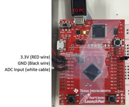
This thread has been locked.

If you have a related question, please click the "Ask a related question" button in the top right corner. The newly created question will be automatically linked to this question.

TM4C123GH6PM's ADC become abnormal while activate its PWM function

Other Parts Discussed in Thread: TM4C123GH6PM

Hi TI Folks,

  Good day to you.

  In my design with TM4C123GH6PM, I met below problem, please advise how to solve the issue?

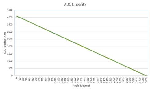
1. I used GPIO PD1 (AIN6) as ADC input to read potentiometer value (0-3.3V). Everything work well, the potentiometer reading is linear.

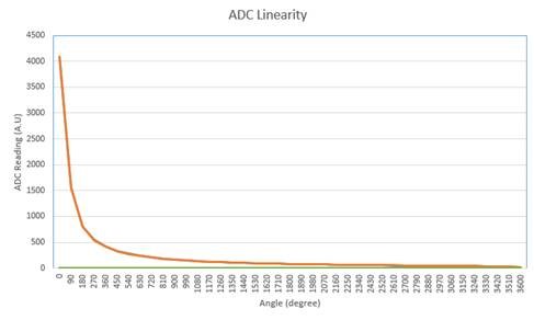
2. After I configure another port (GPIO B7) as PWM output (M0PWM1), The ADC reading become non-linear. 

3. If I disable the PWM configuration, then everything become normal. Any advice for this?

   By the way, I use VisualStudio with tivaware library TivaWare_C_Series-2.1.0.12573. And Same behaviour when I switch to Code composer studio.


Best regards

Jiang WeiJi

  • weiji jiang said:

    GPIO PD1 (AIN6) as ADC input ...  Everything work well, the potentiometer reading is linear ...  configure port (GPIO B7) as PWM output (M0PWM1) ADC reading become non-linear.

    While vastly superior to (famed), "Does not work!" would not (some) mention of the degree/extent of reported, "non-linearity" prove helpful?

    Further - might PB7 be driving a load which produces noise/spikes - or which "challenges" your board's power supply - either of which may disrupt the ADC's operation?   

    Usually it proves helpful to employ another (different) ADC channel - and similarly - MCU PWM output pin/port.   Should the issue remain - a power disturbance is likely - if the issue clears - there may be an (unwanted) signal coupling (or leakage) between (chosen) ADC & PWM pins.

  • Also, check your A/D input circuit. High impedance inputs are vulnerable to noise and other artifacts. All inputs must be appropriately filtered (search bookshelf tag for some TI articles on the care and feeding of A/Ds)

    Also, further useful tests are how does the non-linearity depend on PWM duty cycle?

    Robert
  • Hi Robert,
      Good day to you.
    1. The testing is done in the Tiva-C Launchpad. So I don't think there is filter problem. If I am wrong, please correct me.

    2. If didn't active PWM (To comment off Line 51-64 in the attached main.c), ADC result is linear when changing the potentiometer.

    3. If turn on PWM but no connecting to load (To uncomment Line 51-64 in the attached main.c), ADC result is Non-linear when changing the potentiometer.

    The ADC value did not fluctuate (+/- 2), so this finding is not caused by noise, and ADC operate normally. I tried other PWM0 GPIO and observe this issue too.

    4. See the main.c which used for testing.

    #include <stdint.h>
    #include <stdbool.h>
    #include "inc/hw_memmap.h"
    #include "inc/hw_types.h"
    #include "driverlib/debug.h"
    #include "driverlib/sysctl.h"
    #include "driverlib/adc.h"
    #define TARGET_IS_BLIZZARD_RB1
    #include "driverlib/rom.h"
    #include "driverlib/sysctl.h"
    #include "driverlib/pin_map.h"
    #include "driverlib/gpio.h"
    #include "driverlib/pwm.h"
    
    int main(void)
    {
    	//create array for storing data read from ADC FIFO
    	uint32_t ui32ADC0Value[4];
    	volatile uint32_t ui32TempAvg;
    	volatile uint32_t ui32TempValueC;
    	volatile uint32_t ui32TempValueF;
    	volatile uint32_t ui32Load;
    
    	//enable clock
    	ROM_SysCtlClockSet(SYSCTL_SYSDIV_5|SYSCTL_USE_PLL|SYSCTL_OSC_MAIN|SYSCTL_XTAL_16MHZ);
    
    	//TEST Enable GPIO
    	SysCtlPeripheralEnable(SYSCTL_PERIPH_GPIOD);
    	GPIOPinTypeADC(GPIO_PORTD_BASE,GPIO_PIN_1);	//Configure PD0 as ADC
    
    	//enable adc peripheral
    	ROM_SysCtlPeripheralEnable(SYSCTL_PERIPH_ADC0);
    
    	//average the sample, 64 means take 64 samples and do averaging, so total sampling time will be 64 *4
    	ROM_ADCHardwareOversampleConfigure(ADC0_BASE, 64);
    
    	//reprogramming sampling rate (pending)
    
    	//configure ADC sequencer, sample sequencer 1, processor triggered sequence with highest priority
    	ROM_ADCSequenceConfigure(ADC0_BASE, 1, ADC_TRIGGER_PROCESSOR, 0);
    
    	//configure all four steps in the ADC sequencer, last sequencer require extra setting (ADC_CTL_LE for setting interrupt flag, ADC_CTL_END tell ADC is last)
    	ROM_ADCSequenceStepConfigure(ADC0_BASE, 1, 0, ADC_CTL_CH6);
    	ROM_ADCSequenceStepConfigure(ADC0_BASE, 1, 1, ADC_CTL_CH6);
    	ROM_ADCSequenceStepConfigure(ADC0_BASE, 1, 2, ADC_CTL_CH6);
    	ROM_ADCSequenceStepConfigure(ADC0_BASE, 1, 3, ADC_CTL_CH6|ADC_CTL_IE|ADC_CTL_END);
    
    	//enable ADC sequencer 1
    	ADCSequenceEnable(ADC0_BASE, 1);
    
    /*	// Initialise PB7 M0PWM1
    	ROM_SysCtlPWMClockSet(SYSCTL_PWMDIV_1);				// clock defined in sysctl.c
    	ROM_SysCtlPeripheralEnable(SYSCTL_PERIPH_PWM0);		// TM4C123GH6PM has two modules (0 and 1)
    	ROM_SysCtlPeripheralEnable(SYSCTL_PERIPH_GPIOB);
    	ROM_GPIOPinTypePWM(GPIO_PORTB_BASE, GPIO_PIN_7);
    	GPIOPinConfigure(GPIO_PB7_M0PWM1);
    
    	ROM_PWMGenConfigure(PWM0_BASE, PWM_GEN_0, PWM_GEN_MODE_UP_DOWN | PWM_GEN_MODE_NO_SYNC);
    	ui32Load = (ROM_SysCtlClockGet() / 25000) - 1;
    	ROM_PWMGenPeriodSet(PWM0_BASE, PWM_GEN_0, ui32Load);
    	ROM_PWMPulseWidthSet(PWM0_BASE, PWM_OUT_1, 900);
    	ROM_PWMOutputState(PWM0_BASE, PWM_OUT_1_BIT, true);
    	ROM_PWMGenEnable(PWM0_BASE, PWM_GEN_0);
    */
    
    	while(1)
    	{
    		//clear interrupt
    		ROM_ADCIntClear(ADC0_BASE, 1);
    		ROM_ADCProcessorTrigger(ADC0_BASE, 1);
    
    		//wait the conversion to complete
    		while(!ROM_ADCIntStatus(ADC0_BASE, 1, false)){}
    
    		//after conversion done, start reading out the sequencer FIFO
    		ROM_ADCSequenceDataGet(ADC0_BASE, 1, ui32ADC0Value);
    
    		//do averaging, 2 for rounding issue
    		ui32TempAvg = (ui32ADC0Value[0] + ui32ADC0Value[1] + ui32ADC0Value[2] + ui32ADC0Value[3] + 2) / 4;
    
    /*		//do conversion from Celsius to Farenheit
    		ui32TempValueC = (1475 - ((2475 * ui32TempAvg))/ 4096 )/10;
    
    		ui32TempValueF = ((ui32TempValueC *9) +160)/5;
    */
    
    
    	}
    
    
    }
    

      Please advise how to solve this problem.

    Best regards

    Jiang WeiJi

  • weiji jiang said:
    The testing is done in the Tiva-C Launchpad. So I don't think there is filter problem. If I am wrong, please correct me.

    I don't believe the launchpad has any filtering so, yes, that is an issue.  In addition you need to have impedance matching on the input. Follow my earlier advices of searching the tags, the TI workshops were quite good.

    weiji jiang said:
    The ADC value did not fluctuate (+/- 2), so this finding is not caused by noise,

    That is an overoptimistic assessment. There is a phenomenon called noise rectification.

    Robert