This thread has been locked.

If you have a related question, please click the "Ask a related question" button in the top right corner. The newly created question will be automatically linked to this question.

TM4C129 External Power Issue - Board Will Not Power Up


Hi TI:

I've read most of the threads regarding powering a TM4C129x Launchpad from external power; but, I still can not communicate with the board once I re-wire for external power.     Some of the threads speak of the looking at the "lower left corner" or "VBUS" or "PB1 & VBUS" to attach power to.  I'd like to understand this in terms of the 98 X11 Connector Pins at the bottom of the board.

Setup...

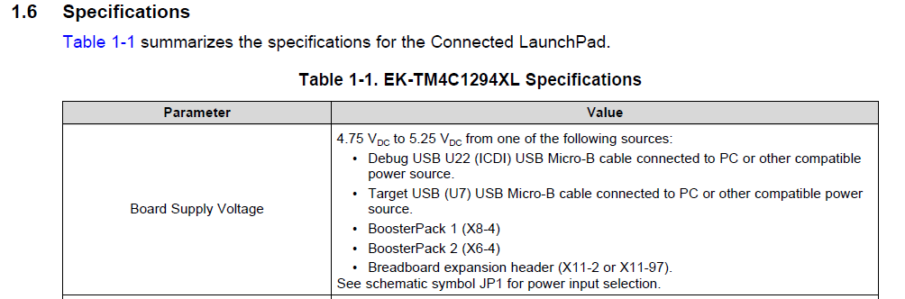
1. Move JP1 (Power Select) from ICD1 to BoosterPack.  Correct?

2. Attach 5V external supply connected to X11 Pin 60 (VBUS) and Ground X11 Pin 62 (GND).  

Questions:

I. Did I select the correct Pins to attach power to or

    (a) are there different X11 Pins that I should be using?  If so, what Pins are they?    similarly.....

    (b) Is there a completely separate two pins that I should be using?  IE. They are not a part of the 98 X11 Connector Pins at the bottom of the board.

          If so, what are they?

II. Did I miss something?  Need to use 3.3V?  JP3?  Other?

Thank you.

Rick

  • Always helpful - yet not (clearly) included w/in your posting - does your board (still) "power-up & communicate" when powered from its "original" power inlet & source?

    If indeed your external power scheme (fails) to power (both) the resident ICDI MCU and/or the board's main MCU - issues such as you describe occur.

    Most always - a thorough review of the board's schematic - focused upon the board's (normal) power inlet & power routings - reveals your path...
  • Hi cb1-

    Thank you for the quick reply.

    The board still powers up using the "original" power inlet & source. All is well there.
    I definitely should have included that in the original post.

    Definitely, appreciate the hints. Regarding schematic reading... I was hoping not to have to embrace a new learning experience; but, of course, there is always great value in it. So... to the schematics we go.

    Thanks

    Rick
  • Thank you. Neither firm nor I have interest in "129" - thus I've no schematics @ the ready - with which to assist.

    The issue IS worthwhile - and the "learning" will prove helpful. From your description I'd bet that (both) of your MCUs (ICDI & Main) are NOT being fully/properly powered. (when our firm designs such, "multi-zoned/MCU'ed boards" we include individual Leds - to confirm that "EACH" Zone/Mcu, is properly powered.)

    It is potentially damaging for you to "Partially Power" your board. (such that a powered IC will connect to one unpowered - in that event one (or if especially unlucky) both may be damaged. Suggest that you avoid any more such "Powering" until "Cavalry" (factory) arrives or your schematic review "lights a path." Bon chance mon ami.

  • Hello Rick,

    You may also want to have a look at the connected launchpad user guide located at this link: www.ti.com/.../spmu365. Specifically, you may want to review section 2.2 on power management. The user guide also has the schematic of the board in it as well.

    Finally, there are a lot of threads within the E2E forum on this topic so a search may prove beneficial as well.
  • Hi Chuck:

    Thank you for the reply.  I have read spmu365 and looked through the forums.  Clearly, I have very little experience with this, so it's very easy to get tripped up on fairly minor questions.

    I was looking for something that said, "If you are connecting the board to external power, then you want to change this Jumper setting and connect your 5V right here (with a circle and arrow) and connect your Ground here (with a circle and arrow).  Thus, the post.

    I definitely appreciate the encouragement to read through the schematics, so... to the schematics.

    Thanks

    Rick

  • Hello Rick:

    It's not presented in as obvious a manner as you are looking for but I think this should answer your question ...

    Additional pinout information for X11 (breadboard connector) can be found on p.26 of the launchpad user guide.

  • Hi Chuck:

    If I hadn't spent time on the schematics per cb1- and yourself, this would not have made as much sense.

    The board is now powered up with no smoke coming from it. Thank you. This is very much appreciated.

    Rick