This thread has been locked.

If you have a related question, please click the "Ask a related question" button in the top right corner. The newly created question will be automatically linked to this question.

A System Tick problem in the bitband example of the EK-TM4C1294XL

Other Parts Discussed in Thread: EK-TM4C1294XL

Hi there,

I am new to the EK-TM4C1294XL board, and just started to run some examples. 

In the binband example, there is a function:

void Delay(uint32_t ui32Seconds). as it comments, which should delay for the specified number of seconds.

But when I ran it, it looked too faster than seconds.

Checking the code, I think the code is good and add some debug variables in it.

void
Delay(uint32_t ui32Seconds)
{
     volatile uint32_t tick;
     uint32_t start = ROM_SysTickValueGet();
    uint32_t end;
    //
    // Loop while there are more seconds to wait.
    //
    while(ui32Seconds--)
   {
   //
    // Wait until the SysTick value is less than 1000.
   //
   while( tick = ROM_SysTickValueGet())
  {
      if(tick > 1000)
         break;
   }

            //
           // Wait until the SysTick value is greater than 1000.
            //
           while(tick = ROM_SysTickValueGet())
           {
               if(tick < 1000)
               break;
            }
       }
      end = ROM_SysTickValueGet();
}

Does anybody get the same problem with me? or did I miss anything?

Thanks,

Henry

  • Hello Henry,

    Are you able to time the actual delay based on the output of the example program? Can you provide how much error you are seeing? Keep in mind, the routine will have up to +/- 1 second of variation given the default counts when the routine is entered. Also, have you done anything with the clock configuration with the example or any other modifications other than the code changes you show above?
  • Hi Chuck,

    Thanks.
    It runs faster than my expectation. I counted the time by clock of my phone, and cannot depend on the system clock.
    Let me try another test program.

    Regards,
    Henry Xin
  • Hello Yuepeng,

    It may be that there is a problem with the clock setup. Can you check to make sure it is operating at the expected frequency?

    Which TivaWare version are you using?
  • Hi Chuck,

    I added a piece of test code in the bitband example project from TivaWare_C_Series-2.1.3.156.

    The system clock is set as:

    //
    // Set the clocking to run directly from the crystal at 120MHz.
    //
    g_ui32SysClock = MAP_SysCtlClockFreqSet((SYSCTL_XTAL_25MHZ |
    SYSCTL_OSC_MAIN | SYSCTL_USE_PLL |
    SYSCTL_CFG_VCO_480), 120000000);

    The test code as:

    while(1)
    {
    //
    // Turn on the LED.
    //
    GPIOPinWrite(GPIO_PORTN_BASE, GPIO_PIN_0, GPIO_PIN_0);
    Delay(2);
    //
    // Turn off the LED.
    //
    GPIOPinWrite(GPIO_PORTN_BASE, GPIO_PIN_0, 0x0);
    Delay(2);
    }

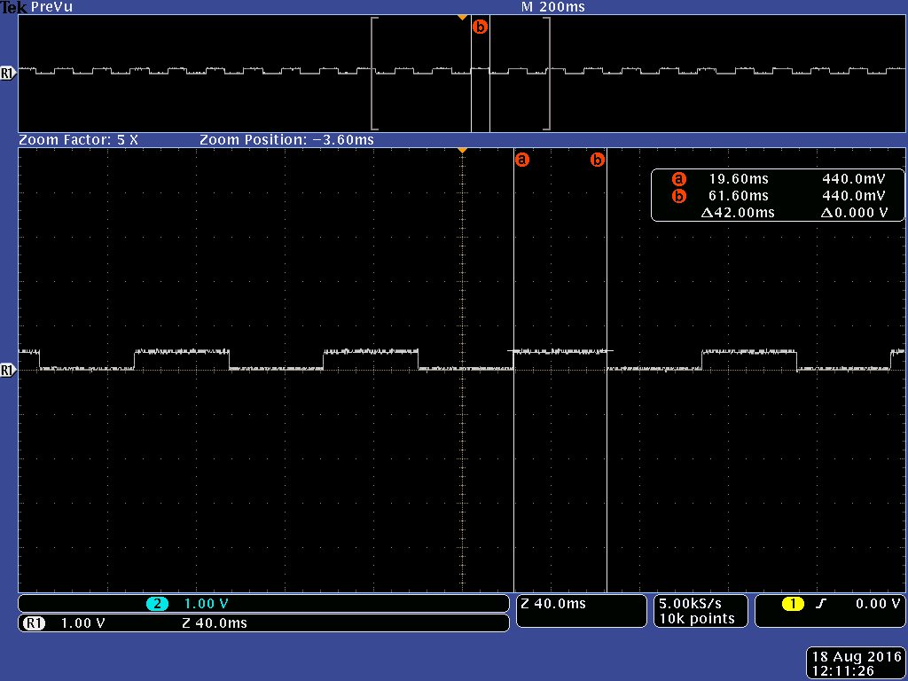
    I measured the LED frequency as:  (The interval between on and off is 42 ms, it is not correct according to the delay setting)

  • Hi Henry,

    I agree that there seems to be something wrong with the delay/system tick interrupt period. Give me a bit to look into it and get back with you with a more definitive answer about what it happening.
  • Hello Henry,

    The problem lies in the initialization of the SysTick reload value. As it states in the driver library user guide and in the header of the flash version, the max value that can be programmed/passed is 16, 777, 216 since the SysTick counter is a 24-bit counter. The example is passing the value returned by SysCtlClockFreqSet which will be 120000000. This results in the incorrect value being programmed into the reload register and thus an incorrect time for the roll over of the counter.

    Note that the value of 1000 used in the Delay function for the compare of the return value of ROM_SysTickValueGet in the while loop is arbitrary since the main goal of this code is to delay for one wrap around cycle without using interrupts. Certainly this could be improved by enabling the SysTick interrupt but for the simplicity of this example it did not make sense to do so.

    To resolve the issue, I changed the reload register init to divide the system clock by 10 changing the reload value to 12,000,000 which is now within the acceptable range. This, however, changes the timer from a seconds timer to a 0.1 seconds timer so all values passed would need to be multiplied by 10 to get 1 second.

    Below is the resulting main function after the change.

    //*****************************************************************************
    //
    // This example demonstrates the use of bit-banding to set individual bits
    // within a word of SRAM.
    //
    //*****************************************************************************
    int
    main(void)
    {
        uint32_t ui32Errors, ui32Idx;
    
        //
        // Set the clocking to run directly from the crystal at 120MHz.
        //
        g_ui32SysClock = SysCtlClockFreqSet((SYSCTL_XTAL_25MHZ |
                                             SYSCTL_OSC_MAIN | SYSCTL_USE_PLL |
                                             SYSCTL_CFG_VCO_480), 120000000);
    
        //
        // Initialize the UART interface.
        //
        ConfigureUART();
        UARTprintf("\033[2J\033[H");
        UARTprintf("Bit banding...\n");
    
        //
        // Set up and enable the SysTick timer.  It will be used as a reference
        // for delay loops.  The SysTick timer period will be set up for one
        // second.
        //
        ROM_SysTickPeriodSet((g_ui32SysClock/10)); // Divide the system clock by 10 to bring into acceptable range.
        ROM_SysTickEnable();
    
        //
        // Set the value and error count to zero.
        //
        g_ui32Value = 0;
        ui32Errors = 0;
    
        //
        // Print the initial value to the UART.
        //
        UARTprintf("\r%08x", g_ui32Value);
    
        //
        // Delay for 0.1 second.
        //
        Delay(1);
    
        //
        // Set the value to 0xdecafbad using bit band accesses to each individual
        // bit.
        //
        for(ui32Idx = 0; ui32Idx < 32; ui32Idx++)
        {
            //
            // Set this bit.
            //
            HWREGBITW(&g_ui32Value, 31 - ui32Idx) = (0xdecafbad >>
                    (31 - ui32Idx)) & 1;
    
            //
            // Print the current value to the UART.
            //
            UARTprintf("\r%08x", g_ui32Value);
    
            //
            // Delay for 1 second.
            //
            Delay(10);
        }
    
        //
        // Make sure that the value is 0xdecafbad.
        //
        if(g_ui32Value != 0xdecafbad)
        {
            ui32Errors++;
        }
    
        //
        // Make sure that the individual bits read back correctly.
        //
        for(ui32Idx = 0; ui32Idx < 32; ui32Idx++)
        {
            if(HWREGBITW(&g_ui32Value, ui32Idx) != ((0xdecafbad >> ui32Idx) & 1))
            {
                ui32Errors++;
            }
        }
    
        //
        // Print out the result.
        //
        if(ui32Errors)
        {
            UARTprintf("\nErrors!\n");
        }
        else
        {
            UARTprintf("\nSuccess!\n");
        }
    
        //
        // Loop forever.
        //
        while(1)
        {
        }
    }
    

  • Hi Chuck,

    Thanks for your answer. I have verified that your code works well.

    Regards,
    Henry Xin