This thread has been locked.

If you have a related question, please click the "Ask a related question" button in the top right corner. The newly created question will be automatically linked to this question.

Crystal Y1 and low frequency harmonic riding MOSC 25Mhz distorting DIVSCLK output frequency.

Guru 56418 points

Other Parts Discussed in Thread: LM3S8971

Testing 2 newer EK-TM4C1294NCPDTi3-XL launch pads and MOSC 25Mhz frequency has low frequency harmonic distorting DIVISCLK signal PQ4, X11-93.

This same 800-890Hz harmonic is also causing issues with HIB modules 32Khz RTCCLK output being proper frequency GPIO-PP3, X11-73.

Scope probe placed Y1 C44 produces 25Mhz sine wave loaded with perhaps 2nd fundamentals appear on DIVSCLK on GPIO- PQ4 & PP3. Scope probe Y1 one side C44 does not impede the running application and it remains oblivious to MOSC frequency some what removed of said harmonic. 

The point is 2 programmed GPTM timers have time diverging edge counts and interrupt times when under load for no good reason (frequency drift). Idea behind desire to program the HIB module RTCCLK leading to this discovery but even that has proved futile to produce 32Khz RTCCLK on GPIO-PP3

There seems to be a hardware issue with Y1 having proper oscillation at the primary fundamental oscillator frequency 25Mhz!

Can this issue be corrected in the field by making capacitor or resistor value changes around Y1?

Previous DIVSCLK thread: https://e2e.ti.com/support/microcontrollers/tiva_arm/f/908/t/540441

Scope capture with Y1 C44 scope probe CH2 seems to compensate for undesired possible 2nd harmonic shown below and distorting 25Mhz DIVSCLK CH1.
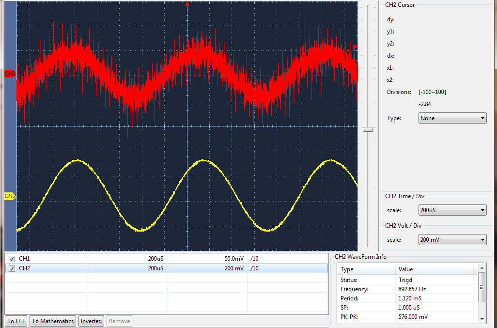
  • Another capture of the possible 2nd fundamental harmonic riding 25Mhz MOSC (CH1). Notice DIVSCLK (CH2 bottom capture) seems to produce 25Mhz and has some nice sine wave character but ONLY when CH1 scope probe Y1 is put on C44.

    That distortion of DIVSCLK (CH2 bottom capture) seemingly is due to the 2nd harmonic riding inside of 25Mhz MOSC (CH1).

    How can this be corrected by simply changing load capacitors C44/C45 or resistor R49 near Y1? 

  • Aliasing (and fairly classic aliasing at that)

    Robert
  • Hello BP101

    I would disagree, that two timers are getting affected by a cross talk on the scope probe and aliasing as it may seem to me when measuring the clock on the crystal. If not careful you may be loading the crystal caps/
  • Hi Amit,

    The timers are diverging for some unknown reason but only under high NVIC interrupt servicing and not due to scope probe on C44. Very odd the DIVSCLK starts producing 25Mhz MOSC but only with the extra capacitance of scope probe on C44. Still can not get a valid 32Khz RTCCLK on PP3 but instead get 25Mhz sine wave when scope probe is on C44.

    That 800hz harmonic seems is one of the crystals secondary frequencies interrupting the primary fundamental. Unstable clock source might explain why the EMAC PHY using MOSC often will for no reason stop communicating over TCP after POR. Back in the day we had similar issues 8Mhz Fox crystal driven by series 74HCT04. Had to use 20pf pull downs and oscillator hysteresis to stop parasitic secondary fundamentals from being present in the CPU clock source.

    Curious though if repeated reentrance calls to SYSCtrlClockFrequencySet() might cause a similar result in MOSC having a period of off time creating that lower harmonic frequency?
  • Hello BP101

    When there is a high NVIC opration, the CPU may be getting delayed in servicing the timers. That is a completely different mechanism and I do not believe it has got anything to do with the "harmonics". Did you check the clock signal with an Active probe or a Passive probe.
  • That would be a first on me past was long ago advised having any harmonic secondary frequency in the primary fundamental of CPU clock source can lead to unpredictable register and clocking behavior.
  • BP101 said:
    That would be a first on me past was long ago advised having any harmonic secondary frequency in

    That's the whole point of mentioning aliasing, there is no secondary frequency. It's a measurement error. At 1uS sample rate (as indicated) you take a single point measurement every 25 periods. Best case is noise, worst case is you get an aliased (false) signal.

    The symptom of the frequency changing as you change time scales is pretty good confirmation of that.

    Amit's note on loading the oscillator circuit is a good bet as well.

    Robert

  • Hi Amit,

    That was the point of trying to rule that possibility out using RTCCLK on PP3 but even that won't work either. Assume probe is passive being X10 AC coupling both channels.

    I'd like to see anything close to 25Mhz on DIVSCLK without holding the scope probe on C44. Oddly some time ago did catch the application vectoring back into main(void) and might RET out causing application reboot looping.

    That must be what is going on here.
  • Agree there could be some capacitive loading from scope probe. That is the point the extra capacitance makes the crystal drive the MOSC amplifier enough to produce DIVSCLK output on PQ4 otherwise not at all. The probe represents 10 megohm impedance AC coupling might have some but very little influence on harmonics.

    Connected 16Mhz external oscillator scope 10K samples depth. Same probe can not drag the frequency below 16Mhz at any horizontal time base setting. Anticipate next might say that is an amplified XTAL source and I argue so is DIVSCLK on PQ4 yet no output that resembles a buffered MOSC of 25Mhz. It stands to reason if Y1 does not have enough frequency magnitude in the fundamental it might under drive the MOSC amplifier but just enough for PLL lock. We past used 20pf pull downs for Fox 8Mhz crystal and C44/45 are only 12pf. Thinking to replace 12pf for 20pf and see what happens. The application is also confirmed not looping in main(void) so the MOSC clock set is not reentrant.
  • > Best case is noise, worst case is you get an aliased (false) signal.

    Have to agree with some of yours and Amit's take on captures. Yet after 12pf C44/C45 are made 24pf sine wave (center capture) is now gone. The cats eyes still appear but only at 1 horizontal setting and 25Mhz MOSC sine wave is more stable, not bouncing as much. Oddly the TM4C123 ICDI 16Mhz crystal used 12pf pull downs so seems odd the same values for 25Mhz crystal. Curious though it would seem to me a 50pf would have been the pull down capacitance and will research the crystals data sheet. It also seems the EMAC is behaving better.

    Really don't care so much to produce DIVSCLK output and only wanted it working as not to load the oscillator with scope probe. Originally was trying to get 32Khz RTCCLK from HIB module output on PP3. There again 32Khz crystal used 12pf pull downs yet the frequency is spot on target. The odd thing is the RTTCCLK is ticking away 1 second intervals. HIB module CCS debug registers confirm are fully configured for external output source, yet no RTCCLK signal occurs other than a convoluted varied frequency wave form.
  • Data sheet NDK crystal has a 9-50Mhz fundamental fixed (primary) frequency order by value.  Must insure desired fundamental remains the primary frequency with little to no secondary harmonics in the final wave form. Seems the trim pull down capacitors might dictate crystals harmonic behavior.

    /cfs-file/__key/communityserver-discussions-components-files/908/Crystal-NDK_2D00_NX3225GA_2D00_STD_2D00_CRG_2D00_2.pdf

  • Seems odd but 24pf is having an GOOD impact on the EMAC being more stable though suggest 18-20pf not the maximum 24pf. The top & center scope captures (2nd posted) are not showing the correct measured signal frequency. However the 1st capture 892Hz (1st post) is showing the results of the suspected secondary harmonic and again the bottom capture showing near 25Mhz DIVSCLK is only present when scope probe is placed on C44.


    Rs is the next part of the equation that could impact RTCCLK (HIB driven) and DIVSCLK (MOSC driven) may reduce frequency magnitude necessary to drive the clock tree gate block input stages.  That seems to infer the RTTCLK/MOSC gate blocks are being under driven by each crystal????

    Is it possible scope probe is some how enabling single ended crystal bypass, NOXTAL (1) register RST=1 cleared 0 and scope probe injects gate bias??

    Clearing both by a single register write as data sheet suggested (MOSCPWR/NOXTAL=0) left a new launch pad inoperative. Yet in Run mode CCS debug shows NOXTAL=0.  

  • > CL = (C1*C2)/(C1+C2) + CSHUNT:

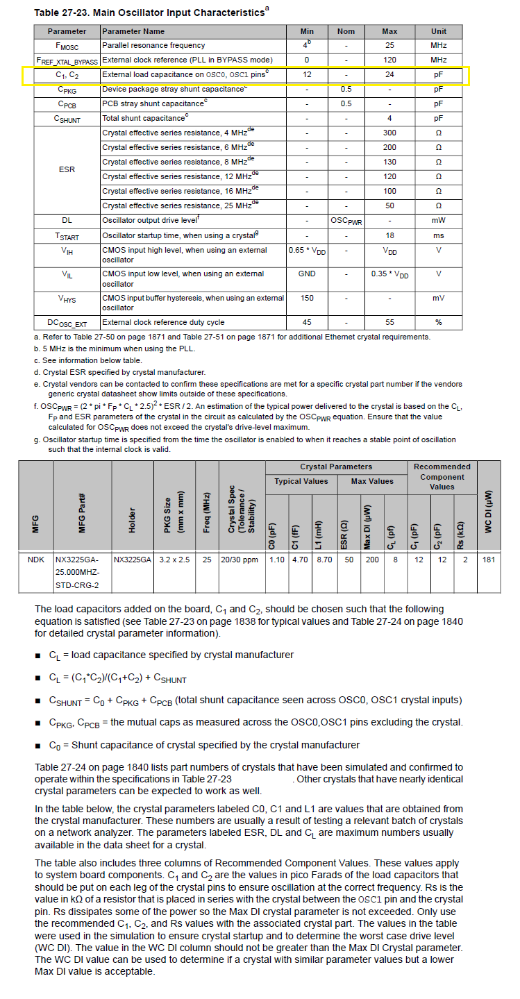
    Seems someone might have made a mistake calculating MOSC total CL:

    CL formula divides (C44, C45) total CL (product/sum) is half or 6pf + shunt 4pf we get 10pf =CL. And when CL= 10pf (C44,C45) crystal load capacitance, DL and Rs factors would also be miscalculated. When crystal load caps are each  24pf (C44,C45) the actual CL=16pf including 4pf shunt before any PCB capacitance is added.

    (24pf *24pf / 24pf +24pf) or  576/48=12pf + 4pf shunt = CL 16pf 

    As a point the ICDI TM4C123 16Mhz crystall on lauch pad C8,C9 = 12pf,  Rs=2k and scope probe frequency remains stable at all 30Mhz horizonal time base. 16Mhz wave form has only very small waviness 1ms horizontal time base. The NDK 16Mhz crystal wave form has little to no secondary harmonics impeding the fundamental frequency. Logically the higher frequency 25hz crystal would require more pull down capacitance than 16Mhz to stop any secondary harmonic driving parasitic oscillatinons in the fundamental frequecny.

    Next thread........

  • BP101 said:

    MOSC 25Mhz frequency has low frequency harmonic distorting DIVISCLK signal PQ4, X11-93.

    This same 800-890Hz harmonic is also causing issues with HIB modules

    We were taught that a "harmonic" is a, "positive, integer MULTIPLE of the original frequency."    (that original frequency is noted as the fundamental frequency.)

    Thus - poster's description of a, "25MHz signal having a "low frequency harmonic" seems FAR, "Off mark."

    On the 20 meter Ham Band (14MHz) we measured harmonic radiation @ 28MHz, (2nd harmonic); 42MHz (3rd harmonic); 56MHz (4th harmonic).  That 4th harmonic proved often "too close" to TV Channel 2 (centered around 52MHz)  - and Low Pass Filters (which "passed signals up to ~30MHz") were normally employed to KILL these "integer MULTIPLES of the original frequency."   (i.e. "harmonics")

    We note that 800-890Hz - as poster reports - would pass thru such a Low Pass Filter unimpeded - thus 800-890Hz has NO CHANCE to be a harmonic of a 25MHz fundamental frequency!  

  • Thus - poster's description of a, "25MHz signal having a "low frequency harmonic" seems FAR, "Off mark."

    RF design guys would probably disagree here. Providing a non-linear component is present (an ordinary diode suffices), those integral harmonics mix in an additive/subtractive fashion, according to their energy levels. This is actually a common method in radio technology to "push" a signal up or down in frequency.

    And this is also the "physical" way the whole spectrum of (unwanted) EMI emissions is created.

    However, I agree with poster CB as well - the energy level of such 800..900Hz VLF mixing product is very minute...

  • >Thus - poster's description of a, "25MHz signal having a "low frequency harmonic" seems FAR, "Off mark."

    Yet XTAL manufacturer NDK uses the word harmonic to describe even the (primary or fundamental) frequency.

    Secondly the vendors FE has yet to explain the absence of DIVSCLK or RTCCLK being produced on either external output. Again MOSC (25Mhz) driven DIVSCLK output (only) occurs when scope probe is placed on active side C44 or C45. What might be occurring is the MOSC clock input is biased enough the output then is able to drive the clock gating input circuitry, otherwise it does not drive clock gating at all. Seeing this odd behavior assures something isn't properly configured. That assumption is made based on the belief vendor would never release an Rev2 silicon with 2 failures, DIVSCLK and RTCLK outputs and not being listed in errata document.

    Oddly vendors test SW of DIVSCLK would not even start the MOSC into oscillation with 12pf C44,C45. Have yet to try same firmware 24pf C44,C45 but suspect (Rs=2k) in all installed XTALS 16-25Mhz even 32Khz is highly suspect. Otherwise RTCCLK and DIVSCLK gating sys control registers never worked to begin with.  

    Again scope captures 25Mhz MOSC when C44, C45 are made 24pf no longer produce the 800-900hz sine wave with 25Mhz riding it. And the ICDI 16Mhz MOSC very same scope probe does not inject or present any secondary sine wave harmonics riding on the primary fundamental frequency 16Mhz. The show me tell me method is the only way to investigate this crime scene.

  • BTW: The 30Mhz scopes captured harmonic frequency (958.466hz) may not be the actual frequency of spikey sine wave (center capture). Though horizontal set 500ns yet is far below division need to see zoomed 25Mhz sine wave peak to peak. So the scope don't always report the correct frequency unless the ADC samples lock to the fundamental in the horizontal time base sample window.

    Past study of crystals vendors documentation stated they can produce undesired parasitic oscillations (harmonics) of the fundamental if not pulled down by proper values of capacitance.

  • BP101 said:

    >Thus - poster's description of a, "25MHz signal having a "low frequency harmonic" seems FAR, "Off mark."

    Yet XTAL manufacturer NDK uses the word harmonic to describe even the (primary or fundamental) frequency.

    Not a contradiction, after all one is an integer multiple.

    Wikipedia said:
    A harmonic of such a wave is a wave with a frequency that is a positive integer multiple of the frequency of the original wave, known as the fundamental frequency. The original wave is also called 1st harmonic, the following harmonics are known as higher harmonics.

    en.wikipedia.org/.../Harmonic

    Robert

  • BP101 said:
    BTW: The 30Mhz scopes captured harmonic frequency (958.466hz)

    This is a measurement error. unless you have put a physical low pass filter on your scope probe you cannot accept this as real measurement.

    Robert

  • f. m. said:
    RF design guys would probably disagree here.

    I don't believe so.   Any signal "Lower in frequency than the fundamental" - and stemming from that fundamental - cannot be a, "Harmonic!" 

    The "mixture" you mention is indeed possible (often desired) but those mixture (sums, differences) are NOT true harmonics.

    Poster is flat wrong to label any signal frequency LOWER than his fundamental as a "harmonic" of that fundamental frequency!

  • Oddly that sounds logical until reading XTAL research is necessary to use spectrum analyzer and a couple of other key points.

    Have to agree CB1 the word harmonic was forever used to describe steps of higher oscillator frequency around the fundamental, never lower. Perhaps the word clock Jitter or white noise more accurately describes case where 900+Khz sine is ridding 25Mhz fundamental. This parallel resonance mode XTAL (C44,C45=24pf) reduced 900+Khz parasitic oscillation, jitter like sine wave below 3.5+Khz. Again the 16Mhz XTAL of ICDI on launch pad very same probe has little to no yet extremely low frequency rolling sine wave but nothing like the MOSC has. Seems to me a low pass probe filter would defeat the objective to fine tune out undesired parasitic oscillations back into alignment with the fundamental, effectively smoothing the primary wave of any jitter effects.

    Oddly the LM3s8971 25Mhz XTAL had used 18pf pull down caps but don't recall seeing 900+Khz sine in the 25Mhz with TEK 50Mhz scope.
    After doing some research XTAL clock jitter etc.. mentions addition of a series resonance capacitor where TI has simply installed Rs=2k and no series cap. A spectrum analyzer is recommended fine tune XTAL oscillators in either resonance mode, only like to have one this case. Another thought is modern day storage scopes are perhaps showing us things that were not sampled as deep 1000KB back in the day of written electronic text books.

  • Oh good Lord!

    You don't often see such effort expended to justify finding meaning in a measurement error.

    Robert

    To be fair I have seen millions spent on a measurement error. Luckily from a distance
  • Like I said agree some of that might be measurement error but not all. MOSC being so close to 480Mhz PLL could be picking up some kind of back wash. Wouldn't you know it Fairchild engineering forum reply to ? a possible harmonic in flyback voltage. lol

    https://community.fairchildsemi.com/thread/2635

    Setting scope acquisition 1000 depth removes inner modulated frequency patterns leaving the larger period yet 10K depth is what the captures were taken. XTAL parallel resonance pull down capacitors were likely suspect when often 18pf pull down caps are selected for 25Mhz MOSC. Extra clock jitter matters and can cause timing issues in ADC and GPTM timers more specifically if it upsets the PLL.

    The likely reason C44,C45 are 12pf on launch pad was a cost driven or supply chain issue trade off. For sure will not be using 12pf C44,C45 in any production runs after this review. Still like to know is the XTAL series resonance can be improved and the gain drive increased for DIVSCLK clock gating to actually produce 25Mhz MOSC. Both DIVSCLK and RTCCLK do not have anything close to what should be produced even with jitter in the mix.

  • If you do the actual work instead of going with the answer you like you would discover that on any timescale longer than about 10uS/div you do not have a valid measurement.

    Robert

    It's an interesting phenomenon in many instances of pathological science that the root cause that lead off in the wrong direction was a bad measurement that could not be questioned. Even when the practitioner knows the technique is invalid they keep coming back to the same measurement
  • The idea behind the authors suggestion to use spectrum analyzer in crystal controlled oscillators was to show those parasitic parallel resonant frequencies obscure in real time captures at the horizontal time base. The basic 10K sample depth of modern storage scopes reveals things the 1k sample depth could not. For instance the modulated 25Khz wave form viewed at 1k sample depth can actually track single modulation pulses though switching to 10K depth same horizontal sweep reveals only 25Khz. That seems to indicate the scope has very stable low end ability in high ended frequencies being very accurate not measurement error.

    You have yet to comment and obviously don't find it odd at all the launch pad used 12pf caps on all 3 crystal (32khz,16Mhz,25Mhz)? Most text reference crystal oscillators mention proper pull down cap value has a lot to do with parallel resonance. Past encounters with lower frequency oscillators proved clock jitter is directly connected to proper aligned resonance at the fundamental harmonic.

    This issue (jitter) seemingly relates to GPTM interrupt events driven simultaneously upon zero count typically end in an MCU faulting condition. Alternatively the default value (next clock cycle) interrupt never causes faults. Other odd timing issues occur in the GPTM driven by 120Mhz PLL derived SYSCLK versus 16Mhz PIOS. It would seem PIOS is highly stable with GPTM while MOSC 12pf even made 24pf (C44,C45) still has far to much MOSC jitter.

    The goal is to reduce jitter MOSC crystal oscillator by making electronic improvements (gain) etc... The purpose of this post DIVSCLK is missing in action and something is still wrong with both RTCCLK and DIVSCLK in the clock gating logic being driven by either oscillator!

  • Measuring jitter would require even more samples than that for frequency. Even 10uS/ div would be too slow. And, yes a spectrum analyzer would be a better tool for that.

    However, that only emphasizes that your current measurement is meaningless.

    Classic GIGO.

    Robert
  • >However, that only emphasizes that your current measurement is meaningless.

    I wouldn't go as far to say meaningless since there is an underlying issue with DIVSCLK and RTTCLK being nonfunctional and DIVSCLK then outputs an distorted sine wave ever scope probe is placed on active side C44.

    Perhaps the 16Mhz MOSC being far more stable all the way down to 1 sec/div has no bearing in your mind and posted capture can simply be dismissed as directly induced measurement error. However the 16Mhz MOSC suggests 25Mhz MOSC posted scope capture +900Khz sine wave is real comparatively. Otherwise we have to then deduce most all scope captures have (fake) artifacts when measured at any frequency or time division.

    The scopes horizontal sweep timing has some bearing with the input signal yet the trigger allows us to synchronizes the sweep to the probes detected frequency and does not directly generate Doppler or beat frequency properties into the input frequency. What comes out the ADC sample pipe is what is put in at the other end, noise and all. That said, if the 10Mohm probe capacitance has that much influence on MOSC frequency, seemingly the crystal is not properly tuned to begin with.  Comparatively 25Mhz MOSC by todays standards of 1.5Ghz MCU oscillators constitutes a low frequency clock source. 

    The issue of DIVSCLK &  RTTCLK not producing any output that remotely resembles either MCU oscillator frequency is concerning and still remains unanswered. That alone gives great reservations amongst seeing other GPTM timing issues around NVIC that leave one asking more questions, few answers in the mix.

  • BP101 said:

    >However, that only emphasizes that your current measurement is meaningless.

    I wouldn't go as far to say meaningless

    You would, however, be wrong.

    Robert

  • Again this post regards the values of C44,C45 made 12pf on launch pad and table 27-3 shows 24pf 25Mhz maximum MOSC. Who knows how accurate the XTAL tolerance is %PPS at the fundamental and likely the formula has some tweaking factor.

    Helpers who only point out error versus suggesting any possible value changes SW or HW are not helping so much here. Must fully rectify failure of DIVSCLK, RTCCLK may help correct NVIC divergence in MOSC/SYSCLK driven GPTM interrupt handlers with triggered 1 shot timers constrained to certain clock domains.

    That NVIC or global interrupt controller has noticeable slow down in 1 second interval timer interrupts diverging from edge counts timer interrupts. Now the counts in the edges per second are far less diverged in the same second 1 shot GPTM driven by PIOSC versus MOSC. SYSCLK GPTM for Edge count interrupts speed 423 edges/second (102Hz) produce 1 interrupt for every 423 edges, fan produces 2 pulses every revolution up to (213Hz) or 6300RPM. No extreme edge timing pushing NVIC to the brink of priority overdrives @1 second one shot GPTM. Yet it does most badly if one shot 1 second GPTM clock source is SYSCLK versus PIOS that constrain total edge counts to maximum of 6800 RPM. Otherwise the input edge speed ends up reporting 30KRPM or higher for MOSC clock source feeding same 1 shot timer for the very same 1 second interval calculation. Something in the clock domains is going Koo Koo and effecting NVIC.

    The divergence of GPTM edge counts/sec do not occur until other GPTM timers, PWM generators and ADC interrupts are tasking NVIC in higher priority interrupts. 

  • BP101 said:
    Again this post regards the values of C44,C45 made 12pf on launch pad

    Line one of the original post

    BP101 said:
    Testing 2 newer EK-TM4C1294NCPDTi3-XL launch pads and MOSC 25Mhz frequency has low frequency harmonic distorting DIVISCLK signal PQ4, X11-93.

    BP101 said:

    Helpers who only point out error versus suggesting any possible value changes SW or HW are not helping so much here.

    Your determination that there is a low frequency harmonic is based entirely on an invalid measurement.


    Robert

  • >Your determination that there is a low frequency harmonic is based entirely on an invalid measurement.

    Might that only be your opinion and there could be some truth in light of other forensic evidence showing face. This is real and you can't make up forensic evidence surrounding the clock sources.

    >Testing 2 newer EK-TM4C1294NCPDTi3-XL launch pads and MOSC 25Mhz frequency has low frequency harmonic distorting DIVISCLK signal PQ4, X11-93.

    And still no answers for distorted wrong frequency DIVSCLK or RTCCLK in light of posting all kinds of forensic evidence tied to the same condition, whether wrongly called a harmonic or not. We have to connect the dots weigh the Bones of forensic evidence to prove internal medicine valid or even the cure.

    More recent forensics prove GPTM driven by 16Mhz PIOSC has far more stable NVIC interrupt servicing than clock source based from 120Mhz SYSCLK derived( 25Mhz MOSC, 480Mhz PLL/4) when GPTM periods are set equal for each source. GPTM configured 1 second one shot or 1 second periodic has significant time drift of interrupt assertions into NVIC when clock source driven by SYSCLK versus PIOSC.
  • Have confirmed the 16Mhz PIOSC driven GPTM edge counts and one shot seconds constrained in 2 interrupts only increases fan taco pulse counts 300 versus 30K RPM as it does with SYSCLK 120Mhz. So it seems MOSC driven GPTM and NVIC interrupts are being delayed in the process.

    Forensic study; The GPTM edge counts and one shot delay periods (1sec) remain the same and only the GPTM clock source was changed from SYSCLK to PIOSC.

    The 480PLL/4 SYSCLK 120Mhz seems to be the cause in the GPTM interrupts being delayed only when ADC/PWM traffic into NVIC ramps up. BTW both GPTM have a higher INT priority than ADC sequencers or PWM interrupts.

    I like to see no RPM divergence in the NVIC interrupt handling even with PIOSC both GPTM. There might actually be another issue with GPTM edge count interrupt UNPENDS being missed, we double clear INT for good measure. These are fairly slow interrupt timings from 102Hz up to 213Hz. It's hard to imagine the NVIC is being swamped by 1 second intervals to process 960 captured edges each interrupt cycle.

    Link to fan taco RPM timer setup:

    https://e2e.ti.com/support/microcontrollers/tiva_arm/f/908/t/471775