This thread has been locked.

If you have a related question, please click the "Ask a related question" button in the top right corner. The newly created question will be automatically linked to this question.

Unable to get LCD to display color

Other Parts Discussed in Thread: EK-TM4C1294XL, EK-TM4C129EXL, MSP430F6659

Hi all,

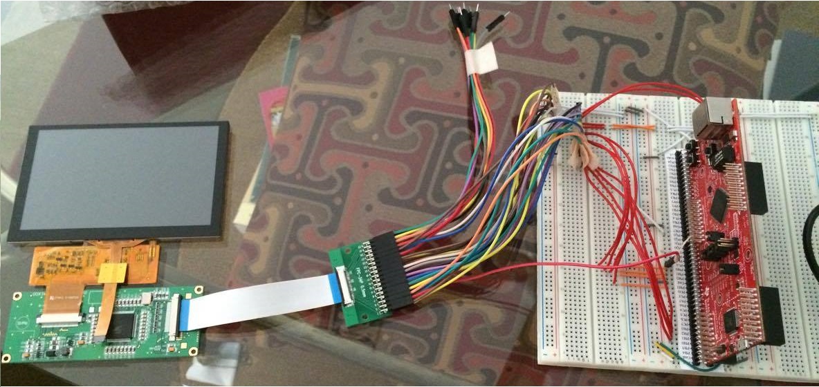
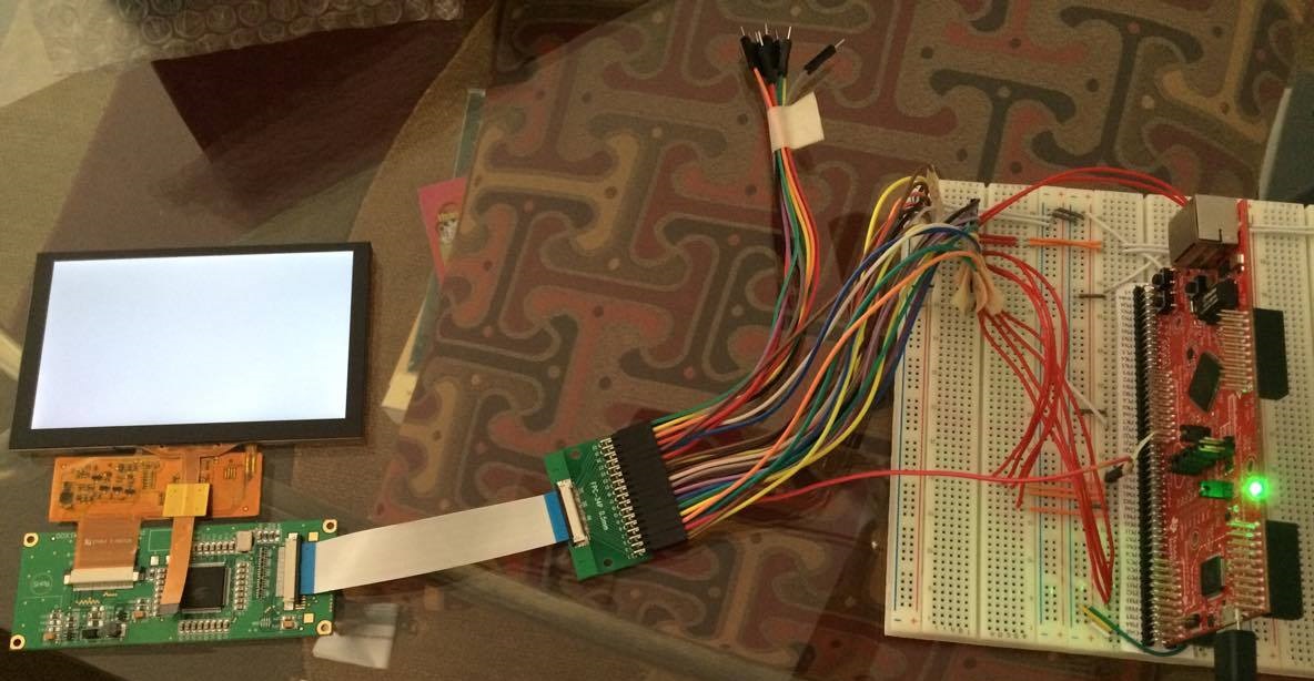
I'm having some trouble interfacing with this LCD that I'm working with. The model for the LCD is NHD-5.0-800480TF-ATXL#-CTP, and it uses the controller board NHD‐5.0‐800480TF‐34 with built-in SSD1963 controller chip. The LCD has a total of 40 pins that connects to the controller board through a ribbon cable, and the controller board give users access to 34 pins to connect to the MCU, also using a ribbon cable (plus some adapters to connect to the breadboard that I have the launchpad plugged into). Here are some extra datasheets for reference. They are in the order of LCD, controller board, and then controller chip SSD1963.

Display Data Sheet.pdf

NHD-5.0-800480TF-34 Controller Board.pdf

Solomon Systech LCD Controller Data Sheet.pdf

I found the code for the Arduino Mega on the company's website, and thus I transfer that over into C for the Tiva C laucnhpad. Here is the link to the Arduino code, followed by the datasheet for the SSD1963, with the difference that this one came from the actual company that made the chip itself (the code examples from the datasheet seems to match the ones on the display company's website):

And now here is my code:

//*****************************************************************************
//
// Main routine.
//
//*****************************************************************************
int main(void)
{
	//
    // Run from the PLL at 120 MHz.
    //
	uint32_t g_ui32SysClock = MAP_SysCtlClockFreqSet((SYSCTL_XTAL_25MHZ |
			SYSCTL_OSC_MAIN | SYSCTL_USE_PLL | SYSCTL_CFG_VCO_480), 120000000);

    //
    // Initialize peripherals.
    //
	initLCD(g_ui32SysClock);

	//
	// Setup LCD for display.
	//
	lcdSetup(g_ui32SysClock);

    //
    // Main loop.
    //
    while (1)
    {
    	lcdDemo(g_ui32SysClock);

    	MAP_SysCtlDelay(g_ui32SysClock / 3); // 1 s delay
    }
}

//*****************************************************************************
//
// Initialize LCD.
//
//*****************************************************************************
void initLCD(uint32_t g_ui32SysClock)
{
	//
	// Enable the peripherals to be used.
	//
	MAP_SysCtlPeripheralEnable(SYSCTL_PERIPH_GPIOH);
	MAP_SysCtlPeripheralEnable(SYSCTL_PERIPH_GPIOM);
	MAP_SysCtlPeripheralEnable(SYSCTL_PERIPH_GPIOQ);
	MAP_SysCtlPeripheralEnable(SYSCTL_PERIPH_GPIOL);

	//
	// Waits for peripherals to be ready.
	//
	while (!MAP_SysCtlPeripheralReady(SYSCTL_PERIPH_GPIOH) &&
			!MAP_SysCtlPeripheralReady(SYSCTL_PERIPH_GPIOM) &&
			!MAP_SysCtlPeripheralReady(SYSCTL_PERIPH_GPIOQ) &&
			!MAP_SysCtlPeripheralReady(SYSCTL_PERIPH_GPIOL));

	//
	// Configure pin PQ3 as output.
	//
	MAP_GPIOPinTypeGPIOOutput(GPIO_PORTQ_BASE, GPIO_PIN_3);

	//
	// Configure pin PH0-PH3 as output.
	//
	MAP_GPIOPinTypeGPIOOutput(GPIO_PORTH_BASE, GPIO_PIN_0 | GPIO_PIN_1 |
			GPIO_PIN_2 | GPIO_PIN_3);

	//
	// Configure pin PM0-PM7 as output.
	//
	MAP_GPIOPinTypeGPIOOutput(GPIO_PORTM_BASE, GPIO_PIN_0 | GPIO_PIN_1 |
			GPIO_PIN_2 | GPIO_PIN_3 | GPIO_PIN_4 | GPIO_PIN_5 | GPIO_PIN_6 |
			GPIO_PIN_7);

	//
	// Configure pin PL0 as output.
	//
	MAP_GPIOPinTypeGPIOOutput(GPIO_PORTL_BASE, GPIO_PIN_0);
}

//*****************************************************************************
//
// Setup/initialize LCD.
//
//*****************************************************************************
void lcdSetup(uint32_t g_ui32SysClock)
{
	//
	// Drive DISP & RD HIGH.
	// Drive WR & REST LOW.
	//
	MAP_GPIOPinWrite(GPIO_PORTH_BASE, GPIO_PIN_0 | GPIO_PIN_1 | GPIO_PIN_2 |
			GPIO_PIN_3, 0x0A);
	MAP_SysCtlDelay(g_ui32SysClock / 3 / (25/3)); // 120 ms delay

	//
	// Drive REST HIGH.
	//
	MAP_GPIOPinWrite(GPIO_PORTH_BASE, GPIO_PIN_2, 0x04);
	MAP_SysCtlDelay(g_ui32SysClock / 3 / (25/3)); // 120 ms delay

	//
	// Perform software reset.
	//
	lcdWriteCommand(0x01);
	MAP_SysCtlDelay(g_ui32SysClock / 3 / (25/3)); // 120 ms delay

	//
	// Set multiplier and divider for PLL.
	//
	lcdWriteCommand(0xE2);
	lcdWriteData(0x1D);
	lcdWriteData(0x02);
	lcdWriteData(0x04);

	//
	// Enable and lock PLL.
	//
	lcdWriteDataToReg(0xE0, 0x01);
	MAP_SysCtlDelay(g_ui32SysClock / 3 / 1000); // 1 ms delay
	lcdWriteDataToReg(0xE0, 0x03);

	//
	// Perform software reset.
	//
	lcdWriteCommand(0x01);
	MAP_SysCtlDelay(g_ui32SysClock / 3 / (25/3)); // 120 ms delay

	//
	// Set LCD mode.
	//
	lcdWriteCommand(0xB0);
	lcdWriteData(0x08);		// 18-bit, FRC enable, dithering disable
	lcdWriteData(0x80);		// TFT mode
	lcdWriteData(0x03);		// Horizontal size = 800 - 1; high byte
	lcdWriteData(0x1F);		// Horizontal size = 800 - 1; low byte
	lcdWriteData(0x01);		// Horizontal size = 480 - 1; high byte
	lcdWriteData(0xDF);		// Horizontal size = 480 - 1; low byte
	lcdWriteData(0x00);		// Even/odd line RGB sequence = RGB

	//
	// Set pixel data format to 8-bit.
	//
	lcdWriteDataToReg(0xF0, 0x00);

	//
	// Set address mode. Image is flipped vertically on display. RGB order from
	// is buffer to display is flipped to BGR.
	//
	lcdWriteDataToReg(0x36, 0x09);

	//
	// Set pixel clock frequency.
	//
	lcdWriteCommand(0xE6);
	lcdWriteData(0x0F);
	lcdWriteData(0xFF);
	lcdWriteData(0xFF);

	//
	// Set horizontal period.
	//
	lcdWriteCommand(0xB4);
	lcdWriteData(0x04);		// HSYCN total = 1056; high byte
	lcdWriteData(0x20);		// HSYCN total = 1056; low byte
	lcdWriteData(0x00);		// HSYNC start position = 88; high byte
	lcdWriteData(0x58);		// HSYNC start position = 88; low byte
	lcdWriteData(0x80);		// HSYNC pulse width = 128 = 127pixels + 1
	lcdWriteData(0x00);		// HSYNC pulse start position; high byte
	lcdWriteData(0x00);		// HSYNC pulse start position; low byte
	lcdWriteData(0x00);		// HSYNC pulse subpixel start position

	//
	// Set vertical period.
	//
	lcdWriteCommand(0xB6);
	lcdWriteData(0x02);		// VSYCN total = 525; high byte
	lcdWriteData(0x0D);		// VSYCN total = 525; low byte
	lcdWriteData(0x00);		// VSYNC start position = 32; high byte
	lcdWriteData(0x20);		// VSYNC start position = 32; low byte
	lcdWriteData(0x01);		// VSYNC pulse width = 1 = 0lines + 1
	lcdWriteData(0x00);		// VSYNC pulse start position; high byte
	lcdWriteData(0x00);		// VSYNC pulse start position; low byte

	//
	// Go into normal mode. Whole display area is used.
	//
	lcdWriteCommand(0x13);

	//
	// Exit idle mode. Full color depth is used for display.
	//
	lcdWriteCommand(0x38);

	//
	// Show image.
	//
	lcdWriteCommand(0x29);
	MAP_SysCtlDelay(g_ui32SysClock / 3 / 100); // 10 ms delay
}

//*****************************************************************************
//
// Test function.
//
//*****************************************************************************
void lcdDemo(uint32_t g_ui32SysClock)
{
	uint16_t i = 0;
	uint16_t j = 0;

	//
	// Set start and end position for column/page address. (full screen)
	//
	lcdWindowSet(0, 799, 0, 479);

	//
	// Start transaction from MCU to display.
	//
	lcdWriteCommand(0x2C);

	//
	// Fill screen with blue pixels.
	//
	for (; i < 480; ++i)
	{
		for (; j < 800; ++j)
		{
			lcdWriteData(0xFF);
			lcdWriteData(0x00);
			lcdWriteData(0x00);
		}
	}
	//
	// Set start and end position for column/page address. (full screen)
	//
	lcdWindowSet(0, 799, 0, 479);

	//
	// Start transaction from MCU to display.
	//
	lcdWriteCommand(0x2C);

	//
	// Fill screen with green pixels.
	//
	for (; i < 480; ++i)
	{
		for (; j < 800; ++j)
		{
			lcdWriteData(0x00);
			lcdWriteData(0xFF);
			lcdWriteData(0x00);
		}
	}

	//
	// Set start and end position for column/page address. (full screen)
	//
	lcdWindowSet(0, 799, 0, 479);

	//
	// Start transaction from MCU to display.
	//
	lcdWriteCommand(0x2C);

	//
	// Fill screen with red pixels.
	//
	for (; i < 480; ++i)
	{
		for (; j < 800; ++j)
		{
			lcdWriteData(0x00);
			lcdWriteData(0x00);
			lcdWriteData(0xFF);
		}
	}
}

//*****************************************************************************
//
// Send a command to LCD.
//
//*****************************************************************************
void lcdWriteCommand(unsigned char command)
{
	uint8_t all_pin = GPIO_PIN_0 | GPIO_PIN_1 | GPIO_PIN_2 | GPIO_PIN_3 |
			GPIO_PIN_4 | GPIO_PIN_5 | GPIO_PIN_6 | GPIO_PIN_7;

	//
	// Drive RS LOW to send command.
	//
	MAP_GPIOPinWrite(GPIO_PORTQ_BASE, GPIO_PIN_3, 0x00);

	//
	// Send 8-bit all together.
	//
	MAP_GPIOPinWrite(GPIO_PORTM_BASE, all_pin, command);

	//
	// Toggle WR. (Active LOW)
	//
	MAP_GPIOPinWrite(GPIO_PORTH_BASE, GPIO_PIN_0, 0x00);
	MAP_GPIOPinWrite(GPIO_PORTH_BASE, GPIO_PIN_0, 0x01);
}

//*****************************************************************************
//
// Send data to LCD.
//
//*****************************************************************************
void lcdWriteData(unsigned char data)
{
	uint8_t all_pin = GPIO_PIN_0 | GPIO_PIN_1 | GPIO_PIN_2 | GPIO_PIN_3 |
			GPIO_PIN_4 | GPIO_PIN_5 | GPIO_PIN_6 | GPIO_PIN_7;

	//
	// Drive RS HIGH to send data.
	//
	MAP_GPIOPinWrite(GPIO_PORTQ_BASE, GPIO_PIN_3, 0x08);

	//
	// Send 8-bit all together.
	//
	MAP_GPIOPinWrite(GPIO_PORTM_BASE, all_pin, data);

	//
	// Toggle WR. (Active LOW)
	//
	MAP_GPIOPinWrite(GPIO_PORTH_BASE, GPIO_PIN_0, 0x00);
	MAP_GPIOPinWrite(GPIO_PORTH_BASE, GPIO_PIN_0, 0x01);
}

//*****************************************************************************
//
// Write/overwrite value in specified register.
//
//*****************************************************************************
void lcdWriteDataToReg(unsigned char reg, unsigned char val)
{
	lcdWriteCommand(reg);
	lcdWriteData(val);
}

Here are some tests that I've did so far:

- Connected a logic analyzer to an oscilloscope, hooked the probes to the data pins PM0-PM7, hooked the channel 1 probe to the WR signal, and stepped through each line in the code to make sure that all values that are sent are being sent as specified.

- Wrote color data to frame buffer, then reading it back out. All data are the same coming out as how they came in, proving that the MCU is communicating correctly with the SSD1963.

Possible causes:

- The LCD or the circuitry on ribbon cable flap connecting to the controller board is faulty/short-circuited.

- I missed something when I transferred the code from Arduino to C.

- I'm not setting the Horizontal Period, Vertical Period, and/or the PLL multiplier and divider correctly (though I've looked through the datasheet for the values on this and I'm quite certain that they are set to the correct values, though I could be wrong, as I'm not 100% sure).

I've been stuck on this for the past couple of weeks, and I'm in desperate needs to get this done in time for my school project. Does anyone have any sort of idea (or have even worked with a NewHaven Display before) on what I might have done wrong, or what other tests I could do? Thanks a bunch.

  • Hello Thomas

    Does the display work as expected or is it that the color information is not getting represented?
  • Hi Amit,

    The color information is not being represented on the display. I can't say for sure that the display is working as expected, as the only thing I've been able to confirm is that the SSD1963 chip on the controller board is receiving color data that I'm sending from the launchpad. Which means I'm also not sure if I am initializing the display correctly either. I've only been assuming that I have because I'm using the C-version of the Arduino code on company's site.

    Thomas
  • Hello Thomas

    Is the backlight on the LCD display switched ON?
  • Hi Amit,

    Yes, the backlight is on. The controller setup the backlight so that it is tied HIGH normally, but can be controlled by GPIO pin to turn on or off. So it does automatically turns on when I supply VDD.

    Thomas
  • Hello Thomas

    Can you please send a snapshot of the what the screen is showing?
  • Hi Amit,

    Here are the pictures you requested. Top is with the LCD off and launchpad not plugged in. Bottom is with the LCD on with the launchpad plugged in and the code running. It should be displaying either a full screen of blue, green, or red.

    Thomas

  • Hello Thomas

    And which mode of transfer are you using? 6800 or 8080 as per the SSD data sheet?
  • Hi Amit,

    The controller board setup allowed for only 8080 to be used by the user.

    Thomas
  • Hello Thomas

    Which GPIO is CS, D/C#, WR# and RD# as per the 8080 timing diagram on page 84 of the SSD1963 specification.
  • Have you tried to read out the ID register(s), to check if your HW interface works ?
    (Should be reg. 0xA3 and reg.0xA8 in your case - with values of 0x06 and 0x98, respectively).
  • Hi Amit,

    - CS I plugged into GND so that it is always selected (suggested in the Arduino code)
    - D/C# is the RS (Register Select) pin on the controller. I assigned this to pin Q3 on the launchpad
    - WR# is the WR pin. I assigned this to PH0
    - RD# is the RD pin. I assigned this to PH1
    - I also assigned the REST (reset) and DISP (display) pin (on the controller-to-MCU side) to PH2 and PH3, respectively

    Thomas
  • Hi f. m.,

    Those ID registers are for the touch panel controller, not for the LCD. That datasheet is kind of confusing. It contains both info on the LCD and the touch panel.

    Thomas

  • Just opened the first PDF ...

    Then, did you try the "read_ddb" command  (SSD1963 datasheet, sect.9.32) ?

    If a read of a register with an known return values doesn't work, there's probably some issue with the interface.

    In that case, compare the sequence/timing with the datasheet (requires a scope ...).

    Not sure if it was mentioned here, but the initialization timing is critical as well. Because of internal charge pumps, such display drivers have startup times of dozens of milliseconds ...

  • Thomas Phan said:
    CS I plugged into GND so that it is always selected (suggested in the Arduino code)

    Tieing that "CS" pin to Gnd - even if the (highly) professional Arduino so suggested (and especially if the Arduino suggested) seems unwise!   Doing so makes your display "sensitive" to data & control signals, "ALL of the Time" - not just during your desired, Display data transfers.

    I agree that initialization of the Display Controller (SSI chip) is key/critical - and you MUST allow sufficient time for each command to be captured by the SSI chip.   That SSI chip had a very long run - I'd suggest that you visit the chip vendor's site - as well as other display makers - with the objective of acquiring additional initialization & code examples.  

    Silent in your report is your measure of all key voltages - especially those felt @ the SSI chip AND the Display - as well.   We're not told, "How you're powering (both) the Display Controller (SSI) and the Display."   It is unlikely that "stealing power" from your MCU board will prove adequate.

    Getting the power right is job one - followed by full & proper initialization.   Note that the SSI chip team believed that the "CS" pin should be "brought out" - suggesting that Arduino's "locking" of that pin was w/out merit!   (surprise that...)

  • Hello Thomas

    Some of the devices use CS# as a strobe signal.
  • Amit Ashara said:
    Some of the devices

    "Devices" - as used here - may not be as clear as you believe...  (i.e. Is "devices" to mean other control chips, or displays, or...?)

    Brevity may not (always) prove best...

  • Hi cb1,

    I'm a little confused on your comment about stealing power. Could you elaborate on that? From my understanding, or at least my assumption of the NewHavenDisplay company, is that the controller board they made for this specific display somehow provides the appropriate power to the display, both for VDD and for backlight (probably through the use of step-up converter(s)). So, and I have asked one of their admins about this too, by providing the 3.3V to the controller, that should be enough to get everything working.

    As for initialization, I just followed the timing given by the Arduino code. Though I have tried adding a 1ms delay between each command (as it seems from the datasheet that the timing between each command is in the nanoseconds), but that didn't do anything either.

    I will try f. m.'s suggestion of reading the DDB info to see if it returns any default values.

    Thomas
  • Hi Amit,

    Does this means that I should try not to ground CS#, but to keep it HIGH and pulling it LOW every time I send a command as shown in the datasheet?

    Thomas
  • Hello Thomas

    That would be my expectation from the interface,
  • By "stealing power" was meant, "From where are you sourcing power to apply to the "Display-Controller" assembly?

    By implication - if you are NOT using a separate power supply for the "Display-Controller" assembly - instead relying upon power harvested from your Launchpad (or similar) that may prove insufficient. (such LPads or Eval Boards are NOT intended as effective (extra) power source devices.)

    Key here is the measurement of voltage at (both) the Controller board (SSI) AND to the Display. (at the display)

    I was the poster who suggested that, "Tieing CS to Gnd" seemed highly suspect. That line should be properly driven - SSI chip's Timing
    Chart should very well detail. And the chip's timing chart ALWAYS trumps an "Arduino method" (especially an Arduino method!)
  • By "stealing power" was meant, "From where are you sourcing power to apply to the "Display-Controller" assembly?

    I have made the experience that the power supply is another critical point with such "MCU board + display" combinations. Flashing and debugging had an very high error rate, until I supplied both boards from an external ("stronger") supply.

    I was the poster who suggested that, "Tieing CS to Gnd" seemed highly suspect. That line should be properly driven - SSI chip's Timing
    Chart should very well detail.

    I surely second that. While I didn't study the driver datasheet in detail, CS might have some function in bus transactions, so a static levels would not work. And if the display driver and the touch driver share signal lines (haven't seen a schematic), a static CS would be perhaps be fatal ...

    (especially an Arduino method!)

    While IMHO Arduino seems rather neutral, that (implied) criticism applies mostly to the superficial "standard Arduino user", who doesn't care about specs, internals and details.

  • f. m. said:
    While IMHO Arduino seems rather neutral, that (implied) criticism applies mostly to the superficial "standard Arduino user"

    May I note that "criticism" was not intended - instead team/I have noted that (often) recommendations and/or reports from (that) source are not backed w/supporting data and/or justification.   Thus - they prove suspect - and "detail & excellence" often are "traded" for "speed & ease."   (the clear "hallmark" of Arduino...)

    Placing (less) than "full faith" in the correctness of "A-sourced" tech advice seems appropriate...

  • Thus - they prove suspect - and "detail & excellence" often are "traded" for "speed & ease."   (the clear "hallmark" of Arduino...)

    Placing (less) than "full faith" in the correctness of "A-sourced" tech advice seems appropriate...

    Just one example from my experience with Arduino-users on different MCU fora (which, I believe, poster cb1 can confirm).

    The most often posted question by these folks is "How fast can I toggle a GPIO on this MCU ?".

    A little research in the internals of a modestly modern MCU - like a Cortex M - reveals the ignorance behind such a query ...

    This, of course, has some influence on the image of Arduino as such in the "Embedded World".

  • Can and (right here, right now) does confirm!

    Yet - even those (bit) beyond "A" may (at times) benefit from the vast eco-system of such devices. (always being careful to insure that (undue) liberties w/"normal design" are not too prevalent...)
  • Just some updates on what I have done since previously.

    - I was able to get in touch with someone from the display company, after which they told me that the controller board I was using is set up to only allow for 16-bit transaction, and I was using 8-bit. (Honestly, the datasheet for this controller wasn't very clear on that)

    - I've tested the LCD with the new updated code for 16-bit format, using the Arduino code that the company employee sent herself, but that didn't work out either. I've just updated her on this.

    - I've tried to set up the code so that it does use the CS signal accurately based on the datasheet's timing (instead of leaving it selected all the time by tying it to GND), but that didn't work.

    - Before I only read data from the frame buffer once after writing to it with enough pixels to fill the entire screen, meaning I only read the first pixel that I wrote. This time I read back 800*480 pixels, first with after writing one consistent value, then with writing different alternating values, and they both returned the data as written.

    The only thing I haven't tried yet is connecting the LCD to an external power supply, but I honestly doubt that is the problem here. Though I will do that as soon as possible.
  • Hello Thomas

    Just my 2 cents looking at he post. Why not use the Kentec Display booster pack which has supported software for both touch and display in TivaWare?
  • Hi Amit,

    I wasn't the one doing research on LCD, but I would guess that because the TI one isn't very popular and well-known. I actually only heard about it yesterday when a TI employee came by our lab. When you search for capacitive touchscreen LCD, the New Haven one is the one that comes up the most.

    Thomas

  • Hello Thomas

    I am not sure if not knowing and not being popular are the same thing. But it will surely jump start your project since it is known to be a working solution and has software support in TivaWare and from MSP432 as well.
  • Hi Amit,

    I will look into it, thanks. I feel like my inexperience and limited knowledge of embedded application must be the reason why I can't get this current LCD working, as I've looked all over NewHaven's forum, and everyone seems to have gotten past the point of where I am now and is experiencing other troubles instead. Hopefully I can resolve this and not end up having to buy another LCD.

    Thomas
  • Hello Thomas

    We may succeed past this point only to get stuck into the next one. I would bet on a safe proven route for you to be able to complete your project.
  • Amit,

    Yet - should we not note - that the (sometimes) "Safe, Proven" one also lands this space - rather often.   (thus perhaps NOT so safe or proven...)

    And - poster's display is 800x480 - far outclassing, (pixel-starved), "safe/proven!"

  • Hello cb1

    I am suspecting that 800x480 would not work as expected and we would end where we started from...
  • Amit,

    Just as the "safe/proven" method (sometimes) works here - so too does the SSD1963 & a correctly mated display.
    In fact - the SSD1963 has a HUGE, successful, installed base.

    Posters working w/out proper experience, equipment & details often fail - neither the SSD Control IC nor the 800x480 display - appears to be (exclusively) at fault...
  • Thomas,

    Were you successful in getting the display working? I am interesting in adding a color display to a project but am unsure if the EK-TM4C1294XL kit can support it. I was looking at the BOOSTXL - K350QVG-S1 by Kentec but I cannot determine if some of the development tools are available.

    I am guessing the Tiva-C graphics libraries work with it and I may need to develop my own touch driver.

    Any suggestions.

    Kind regards,
    Doug
  • Hi Douglas,

    Unfortunately to say, I did not get it to work with the Tiva C. I can, however, say that it's probably an issue related to timing. I was able to get this exact code to work with the Arduino (as it was codes made for the Arduino in the first place and I tried to adapt it to the Tiva C). The only difference between the Arduino and the EK-TM4C1294XL is that it runs at a much slower rate, whereas the latter (at least for how I had it) was operating at 120 MHz. I believe that might have been the problem.

    Thomas

  • Thomas Phan said:
    I can, however, say that it's probably an issue related to timing. I was able to get this exact code to work with the Arduino (as it was codes made for the Arduino in the first place and I tried to adapt it to the Tiva C). The only difference between the Arduino and the EK-TM4C1294XL is that it runs at a much slower rate, whereas the latter (at least for how I had it) was operating at 120 MHz. I believe that might have been the problem.

    Might well be the case. The datasheet of the LCD display is a highly recommended read in this case. It states required delays in the initialization process (due to internal charge pumps), and usually features a diagram and a code example for the initialisation process. Have been there as well ...

  • While delays between Display Initialization Commands are always key/critical - so too are:

    • set-up, hold times of the various strobe signals
    • pulse width of certain key signals

    It is likely that the higher system clock of the ARM MCU may abbreviate certain key signals - and thus violate the SSD specification...

    The fact that an Arduino code example HAS WORKED (poster has stated such) suggests that finding that Arduino code - and carefully, systematically adapting it - provides a reasonable path to success...

    (we should note that there (remains) conflict as regards data bus width.   (8 vs. 16 bits)   It is extremely hard to understand how the O.P. (succeeded) w/Arduino code (and hardware) and then announced that 8 bit data from the ARM MCU proved inadequate.   Surely the extra effort (and wiring) to manage a 16 bit "interconnect" (via the Arduino) would NOT have been forgotten!)

  • cb1_mobile said:
    • set-up, hold times of the various strobe signals
    • pulse width of certain key signals

    It is likely that the higher system clock of the ARM MCU may abbreviate certain key signals - and thus violate the SSD specification...

    A good point to check. But since the TM4C does not have an "automated LCD driver" peripheral, this is not very likely. I had a (hobby) application with a similar display, and used another MCU (twice as fast, 168MHz) and bit-banged an 8-bit, 8080 interface. Even with this MCU, I did not come close to the most settling and transition time limits. That led to my guess about the initialisation timing issue being more likely.

    The Arduino code could serve as template for the sequence. Watch out for delays as well, I expect that code to be rather poorly commented/documented ...

    Using a scope or logic analyzer to compare your bus sequence timings with the LCD display specs is, as always, highly recommended.

  • Your report of that (other) ARM Cortex M4's failing to violate set/transition times convinces me.

    What still deserves review - poster noted that a 16 bit bus was mandated by the display vendor (actually the repackager) yet poster claims (repeatedly) to have succeeded with 8 bit bus. That's a glaring conflict - and throws most everything here into doubt...
  • Sorry, I never made updates to this post as it didn't seem like I would make progress on here.

    I eventually settled for a 20x4 basic character LCD, but before I dropped the NHD LCD, I made some new findings on it. (I'm not sure if I ever claimed that this Arduino code was working, but if I did, apologies. I only found the code on the company's site and assumed that it works with an Arduino, so I took it and tried to adapt it to the ARM MCU)

    - Yes eventually after talking to a tech from NHD, I found out that the model of the driver board that came along with the display was made to only support 16-pin, and was provided codes for the 16-pin data bus version.

    - I also got a hold of an Arduino Mega and tested the code for the 16-pin data bus version, which worked (no surprise there).

    - However, when I tried to adapt the new code for the ARM MCU, that didn't work again. However, it did get to the initialization screen (a mostly white screen with various grainy color dots, kinda like statics; I'm told by the tech that this was normal since this screen means that initialization was successful and that it was showing that static screen because of the empty data buffer). But that was the end of that.

    Since it got to the initialization screen, but did not display a full screen of solid color afterward (I set up the code so that it's supposed to do that), I figured that it was a problem with timing issue of how I'm sending the color data over. I ran out of time to do more debugging and try to get the two (fairly) incompatible pieces of hardwares to work together, so I settled for a simpler LCD. Of course, I also had the choice of using the Arduino to talk to the LCD, and then use the ARM MCU to talks to the Arduino, but our PCB design was close to submission at that point, and we didn't have time to try to add the design of an Arduino Mega to our PCB, so we ended up settling.

    Lesson learn on hardware choices and compatibility for beginners with time-constraint I guess. Hopefully things proceed better for Douglas.
  • Hello,

    I have the same problem as stated above. I have interfaced ssd1963 based display with msp430f6659 but due to low speed now i want to interface it with TIVA EK-TM4C129EXL development board.

    i use grlib  provided by TI for TIVA  development board.

    I have check all signals with scope and it looks ok.

    But display remain white only and nothing display on screen (Not even a garbage value).

    My code is same as posted above.

    Please Help me to get out of this problem..  

  • You may note (by "mousing over" o.p.'s name) that Thomas was last here, Two Years ago!     (i.e. likely, "unobtainable" - and poetic...)

  • I don't know if you have read the rest of the comment yet, but my last one on this post showed the most I could get from working with the display using the Tiva EK-TM4C129EXL. I'm thinking there is some timing issue when sending data over, because it seems unlikely that the code itself is wrong when it also worked on an Arduino, and I basically copy and pasted. Most people on here and on the display forum probably just used the Arduino's route as it is the most compatible, and that's what I would recommend as well. Unless you're not constraint on time, then I'd try to play with all of the values that has to do with refresh rate/timing.

    P.S. It was only slightly more than a year ago so Idk what cb1_mobile is talking about with the two years lol
  • Hello,
    thanks for your reply,

    I am also playing with timing but till not succeed. I have verify my code with above posted code and it is almost same.please give me a code that works in TIVA if it possible. Also i am using graphics library provided for TIVA c series platform so is there any page on internet that help me in this case..
  • Hello, cb1_mobile

    I note that above post is old, But still i have posted my question over here because it is same as above and i want to skip above discussion as i go through it.
    Please do not reply just to increase the point, Reply with some useful information so that one can solve the problem.