This thread has been locked.

If you have a related question, please click the "Ask a related question" button in the top right corner. The newly created question will be automatically linked to this question.

uDMA scatter gather looping


Hi

Based on the information in 

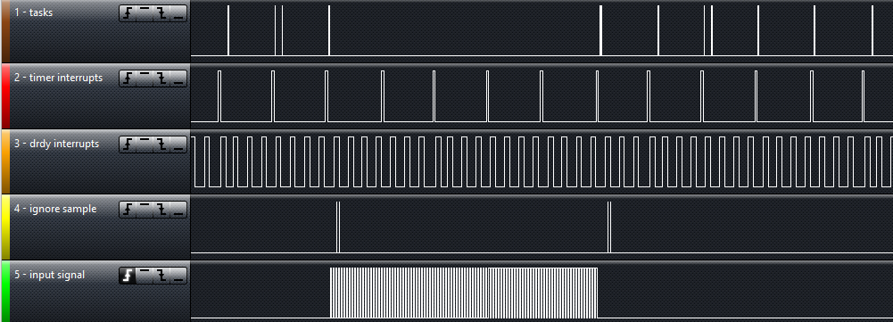
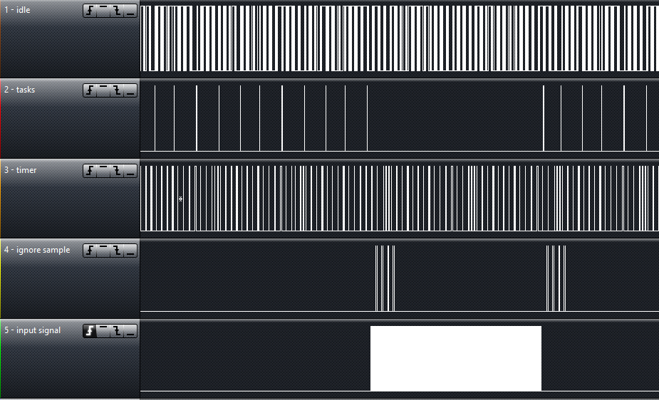
I tried to implement a DMA channel that reloads timer5  with a given constant value upon each rising edge on GPIO PortE Pin5. 

As far as i can tell, this works once (the TIMER_TAILR register shows the value copied by the DMA, not the one set using timerParams.period = TIMER_LOAD_PERIOD; but then my application seems to lock up somehow. 

Is my approach completely wrong, or am I only slightly off?

Any help is greatly appreciated!

Timer Initialization:

/* ********************************************************************************************************************
 *  @brief  Initialize board specific Timer settings.
 *
 *  This function initializes the board specific Timer settings
 *
 * ********************************************************************************************************************/
void B134_332_initTimer(void)
{
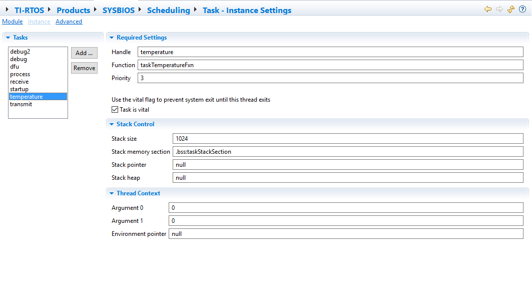
	Timer_Params timerParams;


	Error_Block eb;
	Error_init(&eb);

	Timer_Params_init(&timerParams);
	timerParams.period = TIMER_LOAD_PERIOD;
	timerParams.periodType = Timer_PeriodType_COUNTS;
	timerParams.startMode = Timer_StartMode_USER;
	timerParams.runMode = Timer_RunMode_ONESHOT;
	g_mlsTimer = Timer_create(5, ISR_Timer5, &timerParams, &eb);
	if (g_mlsTimer == NULL) {
		System_abort("Timer create failed");
	}

}

DMA Initialization:

uint8_t GPTMCTL_disable= 0x00;
uint8_t GPTMCTL_enable = TIMER_CTL_TAEN;
uint32_t GPTM_ILR= TIMER_DMA_LOAD_PEROID;

// Temporary storage for the first uDMA primary task, for scatter-gather looping
static tDMAControlTable uDMAsg_LoopTask;

static tDMAControlTable uDMAsg_TaskList[] =
{

	//
	// Task 2: copy source buffer to timer interval load
	//
	uDMATaskStructEntry(1,
						UDMA_SIZE_32,
						UDMA_SRC_INC_NONE,
						&GPTM_ILR,
						UDMA_DST_INC_NONE,
						(void*)(TIMER5_BASE + TIMER_O_TAILR),
						UDMA_ARB_1,
						UDMA_MODE_PER_SCATTER_GATHER
				),


	//
	// Task 4: loop
	//
	uDMATaskStructEntry(
	                4,
	                UDMA_SIZE_32,
	                UDMA_SRC_INC_32,
	                &uDMAsg_LoopTask,
	                UDMA_DST_INC_32,
	                &(B134_332_DMAControlTable[UDMA_CH14_GPIOE & 0x1f]),
	                UDMA_ARB_4,
	                UDMA_MODE_MEM_SCATTER_GATHER
	        )
};

void initMLSFallingEdgeDetection(){
	// initialize interrupt

	uDMAChannelDisable(UDMA_CH14_GPIOE & 0xffff); // Ensure channel is disabled before modifying register
	uDMAChannelAssign(UDMA_CH14_GPIOE);
	uDMAChannelAttributeDisable((UDMA_CH14_GPIOE & 0xffff)|UDMA_PRI_SELECT,UDMA_ATTR_ALL);
	uDMAChannelAttributeDisable((UDMA_CH14_GPIOE & 0xffff)|UDMA_ALT_SELECT,UDMA_ATTR_ALL);
	uDMAChannelAttributeEnable((UDMA_CH14_GPIOE & 0xffff)|UDMA_PRI_SELECT,UDMA_ATTR_USEBURST);
	uDMAChannelAttributeEnable((UDMA_CH14_GPIOE & 0xffff)|UDMA_ALT_SELECT,UDMA_ATTR_USEBURST);


	uDMAChannelScatterGatherSet(UDMA_CH14_GPIOE & 0xffff, 2, uDMAsg_TaskList, true);

	// Copy the primary control structure from the uDMA controltable
	uDMAsg_LoopTask.pvDstEndAddr = B134_332_DMAControlTable[UDMA_CH14_GPIOE & 0xffff].pvDstEndAddr;
	uDMAsg_LoopTask.pvSrcEndAddr = B134_332_DMAControlTable[UDMA_CH14_GPIOE & 0xffff].pvSrcEndAddr;
	uDMAsg_LoopTask.ui32Control = B134_332_DMAControlTable[UDMA_CH14_GPIOE & 0xffff].ui32Control;
	uDMAsg_LoopTask.ui32Spare = B134_332_DMAControlTable[UDMA_CH14_GPIOE & 0xffff].ui32Spare;

	Timer_setPeriod(g_mlsTimer, TIMER_LOAD_PERIOD);

}

Starting the DMA:

void startFallingEdgeDetection(){
	Timer_start(g_mlsTimer);
	GPIODMATriggerEnable(MLS_GPIO_PORT, MLS_GPIO_PIN);
	uDMAChannelEnable(UDMA_CH14_GPIOE & 0xffff);

}

  • Hello Roman

    As far as I an understand your code, it is implemented for one shot mode of operation. So the timer will only fire once and reload, but it will not restart.
  • Hi Amit

    Thanks for the quick reply.

    It is correct that i would like the timer to only cause one interrupt. After initialization i get a continuous burst of rising edges that each should cause a dma transfer reloading the timer and preventing it from running out. This however only seems to happen once.

    Somehow the looping of the sg dma does not work. I however find it hard to exactly pinpoint the issue.  Does this clarify my problem?  

  • Hello Roman,

    And how are the burst of the continuous burst of rising edges generated?
  • The signal on GPIO E4 is an external input to my board. It is either low, or consitsts of variable length pulses with frequencies in the range of 20kHz to 2Mhz.

    To properly interpret my adc signals, i need to know the beginning and end of such pulse bursts.

    Detecting the rising edge is easy, what i am struggling with is detecting the falling edge i.e. the absence of a pulse. By loading the timer on every rising edge to a value equivalent to 50us i can be sure that when the timer runs out the pulses on the input pin must have stopped.

    I tried this completely interrupt based and it works for moderate pulse frequencies, but for higher pulse frequencies i starve my low priority tasks due to the interrupt handling taking up too much time. That's why I'm trying to use a continuously running dma.

  • Hi Amit

    I have continued doing some more debugging work and have made some progress:

    By changing the task list to

    static tDMAControlTable uDMAsg_TaskList[] =
    {
    	
    	//
    	// Task 2: copy source buffer to timer interval load
    	//
    	uDMATaskStructEntry(1,
    						UDMA_SIZE_32,
    						UDMA_SRC_INC_NONE,
    						&GPTM_ILR,
    						UDMA_DST_INC_NONE,
    						(void*)(TIMER5_BASE + TIMER_O_TAILR),
    						UDMA_ARB_1,
    						UDMA_MODE_PER_SCATTER_GATHER
    				),
    	
    
    	//
    	// Task 4: loop
    	//
    	uDMATaskStructEntry(
    	                4,
    	                UDMA_SIZE_32,
    	                UDMA_SRC_INC_32,
    	                &uDMAsg_LoopTask,
    	                UDMA_DST_INC_32,
    	                &(B134_332_DMAControlTable[UDMA_CH14_GPIOE & 0x1f]),
    	                UDMA_ARB_4,
    	                UDMA_MODE_PER_SCATTER_GATHER
    	        )
    };

    (both tasks are now UDMA_MODE_PER_SCATTER_GATHER) 

    I have now been able to observe the uDMA channel reinitializing itself successfully in debugging mode. So that part of my question seems to be solved. 

    The cause for the Timer not reloading seems to be that the Timer peripheral does not seem to realize that the TIMER_TAILR register is written. Also changing the destination to TIMER_TAV does not seem to help. In the next debugging steps, the timer just continues counting down. 

    Similar to using the uDMA to e.g. writhe a ssi peripheral output buffer register, i have assumed that i could also use the uDMA to write the TIMER_TAV or TIMER_TAILR register. Is this not the case? 

    How can I use a DMA transfer to load a given value into my timer while its counting down?

    Thanks a lot in advance for your help!

  • Hello Roman

    As per the timer description "If software updates the GPTMTnILR or the GPTMTnPR register while the counter is counting down, the counter loads the new value on the next clock cycle and continues counting from the new value if the TnILD bit in the GPTMTnMR register is clear. If the TnILD bit is set, the counter loads the new value after the next timeout. If software updates the GPTMTnILR or the GPTMTnPR register while the counter is counting up, the timeout event is changed on the next cycle to the new value. If software updates the GPTM Timer n Value (GPTMTnV) register while the counter is counting up"

    So the question is which mode is being used (up or down count) and what is the setting of the TnILD bit in GPTMTnMR register?
  • Hi Amit

    I noticed this section in the Datasheet and therefore ensured that the TAILD bit is clear and the counter is counting down. Still i did not observe the timer being reloaded, even though I am not absolutely sure it didn't. I ended up writing directly to the TIMER_O_TAV register which is working for me. 
    So most of my initial questions are solved: I can now reload the timer and the scatter gather dma indefinitely reloads itself. 

    Thank you very much for assisting me in getting there!

    Here is the current state of my code for anyone interested: 

    uint8_t GPTMCTL_disable= 0x00;
    uint8_t GPTMCTL_enable = TIMER_CTL_TAEN;
    uint32_t GPTM_ILR= TIMER_DMA_LOAD_PEROID;
    
    // Temporary storage for the first uDMA primary task, for scatter-gather looping
    static tDMAControlTable uDMAsg_LoopTask;
    
    static tDMAControlTable uDMAsg_TaskList[] =
    {
    
    	//
    	// Task 1: copy source buffer to timer interval load
    	//
    	uDMATaskStructEntry(1,
    						UDMA_SIZE_32,
    						UDMA_SRC_INC_NONE,
    						&GPTM_ILR,
    						UDMA_DST_INC_NONE,
    						(void*)(TIMER5_BASE + TIMER_O_TAV),
    						UDMA_ARB_1,
    						UDMA_MODE_PER_SCATTER_GATHER
    				),
    
    
    	//
    	// Task 2: loop
    	//
    	uDMATaskStructEntry(
    	                4,
    	                UDMA_SIZE_32,
    	                UDMA_SRC_INC_32,
    	                &uDMAsg_LoopTask,
    	                UDMA_DST_INC_32,
    	                &(B134_332_DMAControlTable[UDMA_CH14_GPIOE & 0x1f]),
    	                UDMA_ARB_4,
    	                UDMA_MODE_MEM_SCATTER_GATHER
    	        )
    };
    
    void initMLSFallingEdgeDetection(){
    	// initialize dma channel
    
    	uDMAChannelDisable(UDMA_CH14_GPIOE & 0xffff); // Ensure channel is disabled before modifying register
    	uDMAChannelAssign(UDMA_CH14_GPIOE);
    	uDMAChannelAttributeDisable((UDMA_CH14_GPIOE & 0xffff)|UDMA_PRI_SELECT,UDMA_ATTR_ALL);
    	uDMAChannelAttributeDisable((UDMA_CH14_GPIOE & 0xffff)|UDMA_ALT_SELECT,UDMA_ATTR_ALL);
    	uDMAChannelAttributeEnable((UDMA_CH14_GPIOE & 0xffff)|UDMA_PRI_SELECT,UDMA_ATTR_USEBURST);
    	uDMAChannelAttributeEnable((UDMA_CH14_GPIOE & 0xffff)|UDMA_ALT_SELECT,UDMA_ATTR_USEBURST);
    
    
    	uDMAChannelScatterGatherSet(UDMA_CH14_GPIOE & 0xffff, 2, uDMAsg_TaskList, true);
    
    	// Copy the primary control structure from the uDMA controltable
    	uDMAsg_LoopTask.pvDstEndAddr = B134_332_DMAControlTable[UDMA_CH14_GPIOE & 0xffff].pvDstEndAddr;
    	uDMAsg_LoopTask.pvSrcEndAddr = B134_332_DMAControlTable[UDMA_CH14_GPIOE & 0xffff].pvSrcEndAddr;
    	uDMAsg_LoopTask.ui32Control = B134_332_DMAControlTable[UDMA_CH14_GPIOE & 0xffff].ui32Control;
    	uDMAsg_LoopTask.ui32Spare = B134_332_DMAControlTable[UDMA_CH14_GPIOE & 0xffff].ui32Spare;
    
    
    }

    The only issue remaining is that all my RTOS tasks cease functioning while DMA Channel 14 is enabled. Here is what I observe on my logic analyzer (GPIO's being toggled upon entry and exit of any task, timer ISR function, and GPIO ISR function, as well as an indication of the start and end of bursts i detect on the input)

    Here is the code relevant for the burst detection:

    void initMainLaserSuppression() {
    	if(0==GPIO_read(MLS_BOARD_GPIO)){
    		//pin is actively pulled down
    		initMLSFallingEdgeDetection();
    		GPIO_enableInt(MLS_BOARD_GPIO,GPIO_INT_RISING);
    	}
    }


    void ISR_GPIOPortE(){
    	GPIOIntClear(MLS_GPIO_PORT,MLS_GPIO_INT_FLAG);
    	g_mlsDirtyFlag=1;
            Timer_start(g_mlsTimer);
    	GPIODMATriggerEnable(MLS_GPIO_PORT, MLS_GPIO_PIN);
    	uDMAChannelEnable(UDMA_CH14_GPIOE & 0xffff);
    }
    
    void ISR_Timer5(){
    
    	g_mlsDirtyFlag=1;
    	uDMAChannelDisable(UDMA_CH14_GPIOE & 0xffff);
    	GPIODMATriggerDisable(MLS_GPIO_PORT,MLS_GPIO_PIN);
    	GPIOIntClear(MLS_GPIO_PORT,MLS_GPIO_INT_FLAG);
    
    }

    The tasks don't get executet as long as DMA channel 14 is enabled, not depending on the DMA actually getting triggered by the GPIO peripheral or not. If I don't disable the DMA channel in ISR_TIMER5 , the tasks never get executed again.

    Do you know by what this could be caused? Can you point me in any direction where to continue debugging this issue? Any help is greatly appreciated!

  • Hello Roman,

    It seems that the DMA task has finished and the DMA request are being generated for which the interrupt is being generated. The DMA must be re-initialized on completion of the tasks. If no immediate re-initializtion is required, then it must be disabled.
  • Hi Amit

    I am sorry, but I don't quite understand your reply. 

    I set up the scatter gather dma to loop itself (i.e. copy the initial primary control table entry back to its original location in the last task of my task list.) Therefore I would have thought the DMA will never finish its task. This is also what I observe. The DMA performs its task whenever it is enabled, without ever re-initializing it. 

    The issue I have is that any tasks configured in the context of the TI-RTOS or more specifically in the SYS/BIOS cease to be executed while the DMA is running. I fail to see the connection between the DMA and these tasks getting triggered for execution. I also can not imagine that these tasks get starved during that time, since I don't change the processing load at all. 

    Here is the example code of such a task:

    /*********************************************************************************************************************//**
     * @brief task used to read the temperature.
     *
     * collectTemperature() is doing the reading/processing.
     *
     * @param arg0 argument 0
     * @param arg1 argument 1
     *************************************************************************************************************************/
    Void taskTemperatureFxn(UArg arg0, UArg arg1)
    {
        while(runtime)
        {
    
    	RegisterGPIOToToogle(START, TOOGLE_ALL_TASKS);
            collectTemperature();
            UpdateHeater();
    
            RegisterGPIOToToogle(STOP, TOOGLE_TEMPERATURE);
    
        	Task_sleep(100);
        	
        }
    }

    Configured as follows:

  • One more thing: 

    For debugging purposes, I registered an idle function to be executed when all tasks are blocked:

    Idle.idleFxns[0] = "&_c_idle00";
    Task.allBlockedFunc = Idle.run

    The Idle function does get executed while the DMA channel is enabled:

    It therefore seems that the DMA channel being active is somehow inhibiting the tasks from getting unblocked. I have however no clue how these two could be connected. 

  • Hello Roman

    Do you mean the GPIO toggle for the signal marked "tasks" and "ignore sample" do not happen, when the "input signal" starts toggling?
  • Hi Amit
    Only Tasks don't get executed (visible on the LA by the missing toggling of the GPIO on the "tasks" signal). The "Ignore Sample" toggles just indicate that I correctly identified the start and end of the toggling burst on "input signals" (this gpio toggling is caused by an execution of ISR_Timer5 or ISR_GPIOPortE)
    Regards
    Roman
  • Hello Roman,

    And what is the rate of the GPIO toggle?
  • "input signal" toggles in that screenshot with 25kHz. In the final application it can be anything between 20kHz and ~500kHz (edit: preferably it will work up to 2Mhz).

  • Hello Roman

    That is a very nominal rate for UDMA. The only thing that can be happening is somehow the DMA interrupt handler is getting triggered via the peripheral causing it to go the interrupt handler all the time till the DMA channel is not disabled.

    The triggering peripheral has an interrupt mask for the DMA done interrupt. If the condition is not being cleared then the CPU may just be entering and exiting the interrupt handler.
  • Hi Amit
    Thanks for the tip. I have not thought of that.
    Will the scatter gather transfer generate an interrupt every time it switches between primary and alternate?
    That interrupt will be triggered on the GPIOPortE Interrupt vector, right? Is there a way I can mask it? In the datasheet the GPIOIM (GPIO Interrupt Mask) register only shows 8bits for the 8 pins on Port E which can be used to mask interrupts. Can I also mask the interrupt caused by the DMA?

    In the uDMA section I only found the DMA Channel Interrupt Status (DMACHIS) Register. Would I have to clear that one?

    However, the whole point of using the infinite loop scatter gather dma was to get rid of any interrupt handlers being called. I would therefore really like to prevent the DMA done interrupt from being handled at all. Can I somehow do that?

    Thanks again for your help!
    Regards
    Roman
  • Hello Roman,

    It should generate a done interrupt at the end of the task. Since the GPIO is the source of the DMA trigger, the GPIO's Interrupt mask register must have the bit DMAIME clear so that any interrupt coming from the DMA does not cause a GPIO peripheral interrupt.
  • Hi Amit

    I unfortunately can't find a DMAIME bit in the GPIOIM Register described in the TM4C123 Datasheet:

    Am I looking in ther wrong place?

  • Hello Roman

    Are you using TM4C123x device?
  • Hello Roman,

    OK. The DMA had a rather convoluted mechanism in TM4C123. The DMA and interrupt for the peripheral done is triggered on the peripheral interrupt. When the interrupt handler is called, the CPU must check the interrupt status bit of the peripheral and the UDMACHIS to find out the cause of the interrupt. If the uDMACHIS is set then it must be cleared.
  • Is there a way to mask the uDMA interrupt so it doesn't trigger the peripheral interrupt handler? As stated before, if I have to go clear the UDMACHIS bit for every execution of the uDMA, I could have done the whole implementation interrupt based with the exact same performance...
    Is there a way to achieve my goal without wasting that much processing power?
  • Hello Roman,

    No, there is no way to mask it. The Interrupt status must be cleared. The only method to avoid it is to disable the interrupt in the NVIC for the peripheral that triggers the DMA request by using IntDisable API call with the interrupt number of the peripheral as the argument.
  • Hi Amit

    I checked wheter the UDMA_CHIS bit is set and this does not seem to be the case:

    I don't think i clear it anywhere. Does the RTOS clear it somewhere without my knowledge?

  • Hello Roman

    I am not sure if the RTOS handles it internally. However a quick way to eliminate this is to disable the interrupt vector in the NVIC.
  • Hi Amit

    I tried disabling the interrupt in the NVIC when enabling the DMA channel and enabling it again after disabling the dma channel:

    void ISR_GPIOPortE(){
    	GPIOIntClear(MLS_GPIO_PORT,MLS_GPIO_INT_FLAG);
            IntDisable(INT_GPIOE);
    	g_mlsDirtyFlag=1;
            Timer_start(g_mlsTimer);
    	GPIODMATriggerEnable(MLS_GPIO_PORT, MLS_GPIO_PIN);
    	uDMAChannelEnable(UDMA_CH14_GPIOE & 0xffff);
    }
    
    void ISR_Timer5(){
    
    	g_mlsDirtyFlag=1;
    	uDMAChannelDisable(UDMA_CH14_GPIOE & 0xffff);
    	GPIODMATriggerDisable(MLS_GPIO_PORT,MLS_GPIO_PIN);
    	GPIOIntClear(MLS_GPIO_PORT,MLS_GPIO_INT_FLAG);
            IntEnable(INT_GPIOE);
    
    }

    I still observe the same behaviour that the tasks do not get executed:

  • Hello Roman

    I am still at a loss to explain why the tasks are not getting executed. May be it would be good to ask the question on the RTOS forum.
  • Hi Amit

    As you suggested, I posted my question in the RTOS forum.

    I however made an interesting observation, that I hope you might be able to explain or that would give you another idea, what further actions I could take:

    Regards,

    Roman

  • Hello Roman

    Yes, that is correct. On TM4C123x the uDMA has a nuance (mentioned in the datasheet). The DMA request comes is generated by using the interrupt line.

    "When μDMA is enabled for a peripheral, the μDMA controller stops the normal transfer interrupts for a peripheral from reaching the interrupt controller (the interrupts are still reported in the peripheral's interrupt registers). Thus, when a large amount of data is transferred using μDMA, instead of receiving multiple interrupts from the peripheral as data flows, the interrupt controller receives only one interrupt
    when the transfer is complete. Unmasked peripheral error interrupts continue to be sent to the interrupt controller."
  • I was aware of this although i thought the "routing"of the interrupt was controlled by enabling or disabling the DMACTL register bits in the gpio peripheral. From your answer i understand that this is not the case?

    Furthermore i can't explain why the Timer2 interrupts would stop getting serviced. This is also the more worrying issue to me. I can live without gpio port e interrupts, but not without those from timer 2.

  • Hello Roman

    This was a limitation for the uDMA model on the TM4C123x devices and was fixed in the TM4C129x
  • I am sorry, but i don't understand what you mean by this limitation. Could you elaborate?
  • Hello Roman

    The fact when the DMA channel masks the peripheral interrupts. Only error interrupts (for some of the data peripherals) are still seen by the NVIC.
  • Hi Amit

    I understand that if I use the GPIOPortE Peripheral to actively generate DMA requests, its interrupts will not reach the NVIC. However there are a number of places where I can mask/disable these DMA requests or the DMA transfers and the datasheet is not very clear in the effect they have on this behaviour:

    In the DMA:
    DMAREQMASKSET
    DMAENASET
    DMACHASGN 

    Or in the Peripheral:
    GPIODMACTL

    Which of those actually determine if regular (non error) peripheral interrupts will reach the NVIC? 

    Regards,

    Roman

  • Hello Roman

    I would need to check with the Designers to ascertain that.
  • Hi Amit

    I would appreciate it very much if you could provide me with that information. Thanks a lot in advance!

    In the meantime I have spent some more time debugging and tried forcing RTOS to use Timer3 instead of Timer2 for its task scheduling by occuping Timer2 with a dummy.

    The result is positive in the way that it gives me a workaround for the time being:

    As you can see, the tasks keep getting executed even while the dma channel 14 is active.

    My only explanation for this behaviour is that just because Timer 2 could be configured to trigger DMA Channel 14 transfers, its interrupts are blocked from reaching the NVIC whenever DMA channel 14 is enabled (with GPIOE assigned to it). 

    Is this conclusion correct? And is that supposed to be this way?

    Regards

    Roman

  • Hello Roman

    Yes, that would be correct interpretation.
  • Hi Amit

    Thanks for confirming that.

    Since to me that seems like a serious limitation complicating the use of the uDMA a lot, I would like to ask you if it were possible that you could quickly summarize the expected behaviour of an enabled DMA channel (e.g. 14) on interrupts of the assigned and the potentially assignable peripherals?

    I was not able to find any indication of such cross implications in the TM4C123 datasheet. 

    Regards

    Roman

  • Hello Roman

    The implication of the interrupt being masked when using the DMA is given in the datasheet. Section is 9.2.10 "Interrupts and Errors" in the DMA chapter.
  • I am familiar with that section. It states the following:

    When μDMA is enabled for a peripheral, the μDMA controller stops the normal transfer interrupts for a peripheral from reaching the interrupt controller (the interrupts are still reported in the peripheral's interrupt registers).

    This however contradicts what I observe: When I enable uDMA for a peripheral (GPIO E), the uDMA controller seems to stop normal interrupts of another peripheral (TIMER 2A).  

  • Hello Roman

    Hmm, that is because the Timer 2A and GPIO E have both got the same channel assignment of Channel 14. I think it is because of this that the interrupt of Timer 2A (which is unrelated to the DMA) is getting blocked.
  • Hi Amit

    I agree, that could be the reason. But is this intentional?

    Do I have to expect this behaviour on all channels concerning all peripherals or is this an exception?

  • Hello Roman,

    No, this is not intentional and could be a bug in the design. I will need to test it out to confirm if it is a bug or not.
  • Hi Amit

    Were you able to get any additional information on this issue?

    Regards,

    Roman

  • Hello Roman,

    Apologies for not having responded earlier. I can confirm that there is a blocking mechanism which prevents interrupt from a module on the same channel map from reaching the NVIC, even if it is not being used for DMA operations. I am trying to analyze the root cause, as to why it is occurring.