This thread has been locked.

If you have a related question, please click the "Ask a related question" button in the top right corner. The newly created question will be automatically linked to this question.

Problem trying to use ADC1 and Touchscreen library at the same time

Hello everyone.

I'm new using the TM4C129x, for the moment I want to read values from two ADC channels with the ADC1 (because I see that ADC0 is used by the touchscreen) and at the same time use the touchscreen, everything working in FreeRTOS.

The problem is that when I try to put them to work together the touch doesn't work, I have a task to control the ADC and another for the LCD, both tasks have the same priority.

I have check the individual codes running alone and both works but when I try to put them together it fails the touch. Below I leave you what I think is the important code

First the ADC configuration:

void
InitADC(void)
{
    //
    // Habilita el módulo del ADC1
    //
    ROM_SysCtlPeripheralDisable(SYSCTL_PERIPH_ADC1);
    ROM_SysCtlPeripheralReset(SYSCTL_PERIPH_ADC1);
    ROM_SysCtlPeripheralEnable(SYSCTL_PERIPH_ADC1);
    
    while(!(ROM_SysCtlPeripheralReady(SYSCTL_PERIPH_ADC1)));
    
    //
    // Habilita el puerto E (Ahí están los canales del ADC que vamos a usar)
    //
    ROM_SysCtlPeripheralDisable(SYSCTL_PERIPH_GPIOE);
    ROM_SysCtlPeripheralReset(SYSCTL_PERIPH_GPIOE);
    ROM_SysCtlPeripheralEnable(SYSCTL_PERIPH_GPIOE);
    
    while(!(ROM_SysCtlPeripheralReady(SYSCTL_PERIPH_GPIOE)));


//******************************************************************************
//
//              Start the ADC sequence configuration
//
//******************************************************************************    
    
    //
    // Configura dos pines del puerto E (E1 y E2) como entradas del ADC
    //
    GPIOPinTypeADC(GPIO_PORTE_BASE, GPIO_PIN_3);
    GPIOPinTypeADC(GPIO_PORTE_BASE, GPIO_PIN_2);

    //
    // Configura el ADC para trabajar a 16MHz (480MHz(reloj principal) entre 30(prescaler))
    //
    ADCClockConfigSet(ADC1_BASE, ADC_CLOCK_SRC_PLL | ADC_CLOCK_RATE_FULL, 30);

    //
    // Configura el secuenciador 0 del ADC1 para que sea disparado por software
    // con prioridad 0
    //
    ROM_ADCSequenceConfigure(ADC1_BASE, 0, ADC_TRIGGER_PROCESSOR, 0);
    
    //
    // Configura los steps del secuenciador 0 para tomar una muestra del canal 0
    // y después una muestra del canal 1, esta última muestra dispara la
    // interrupción del ADC y finaliza la secuencia.
    //
    ROM_ADCSequenceStepConfigure(ADC1_BASE, 0, 0, ADC_CTL_CH0);
    ROM_ADCSequenceStepConfigure(ADC1_BASE, 0, 1, ADC_CTL_CH1 | ADC_CTL_IE | ADC_CTL_END);
    
    //
    // Limpia la interrupción del ADC antes de habilitarla para evitar falsos
    // disparos.
    //
    ADCIntClearEx(ADC1_BASE, ADC_INT_SS0);
    ROM_ADCIntEnableEx(ADC1_BASE, ADC_INT_SS0);
    
    //
    // Habilitamos el secuenciador 0 para que comience el muestreo
    //
    ROM_ADCSequenceEnable(ADC1_BASE, 0);
    
//******************************************************************************
//
//              Finish the ADC sequence configuration
//
//******************************************************************************  
    
    //
    // Se habilita la interrupción del ADC
    //
    ROM_IntEnable(INT_ADC1SS0);
}

ADC interrupt handler:

void
ADC1SS0IntHandler(void)
{
    uint32_t samples[NUM_SAMPLES];
    int iRetVal = 0;
    
    //
    // Clear any pending status
    //
    ADCIntClearEx(ADC1_BASE, ADC_INT_SS0);
    
    //
    // Lee el valor obtenido por el ADC
    //
    iRetVal = ADCSequenceDataGet(ADC1_BASE, 0, samples);
    
    if(iRetVal == 2)
    {
      //Some calculations
    }
}

ADC Task:

void
ADCTask(void *pvParameters)
{   
    //
    // Habilita el reloj para el TIMER0
    //
    ROM_SysCtlPeripheralEnable(SYSCTL_PERIPH_TIMER0);
    
    //
    // Habilita interrupciones del procesador
    //
    ROM_IntMasterEnable();
    
    //
    // Configura el submodulo TIMER_A del modulo TIMER0
    //
    ROM_TimerConfigure(TIMER0_BASE, TIMER_CFG_PERIODIC);
    ROM_TimerLoadSet(TIMER0_BASE, TIMER_A, 120000);
    
    //
    // Setup the interrupts for the timer timeouts.
    //
    ROM_IntEnable(INT_TIMER0A);
    ROM_TimerIntEnable(TIMER0_BASE, TIMER_TIMA_TIMEOUT);
    
    //
    // Habilita los timers
    //
    ROM_TimerEnable(TIMER0_BASE, TIMER_A);
  
    
    InitADC();

    while(1)
    {
      if(DoOperations)
      {
        DoOperations = false;
        TOCOandBPMCalculation();
      }
      
    }
}

Display Task

void
WidgetTask(void *pvParameters)
{
    //
    // Add the compile-time defined widgets to the widget tree.
    //
    GetScreen(1,&Imagen_a_mostrar);
    
    WidgetAdd((tWidget*)&g_sBackground, (tWidget*)Imagen_a_mostrar);
    WidgetAdd(WIDGET_ROOT,(tWidget*)&g_sBackground);
    
    //
    // Paint the widget tree to make sure they all appear on the display.
    //
    WidgetPaint(WIDGET_ROOT);
   

    //
    // Loop forever, processing widget messages.
    //
    while(1)
    {
        //
        // Process any messages from or for the widgets.
        //
        WidgetMessageQueueProcess();
    }
}

Sorry for the code in Spanglish, I hope you can help me and feel free to ask for more parts of the code and I'm using IAR by the way.

Regards, Juan


  • Hello Juan

    I think the issue is that the timer trigger for the ADC of touchscreen has got replaced with processor trigger. Please check the trigger source register of the ADC for the touch screen.
  • Hi Amit,

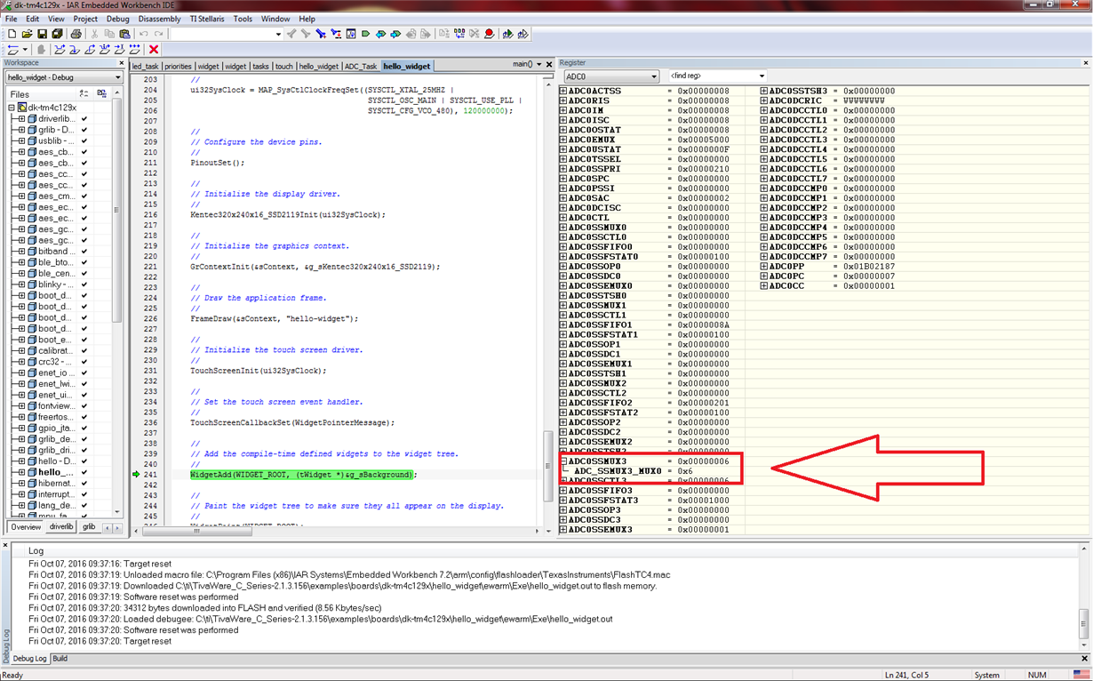
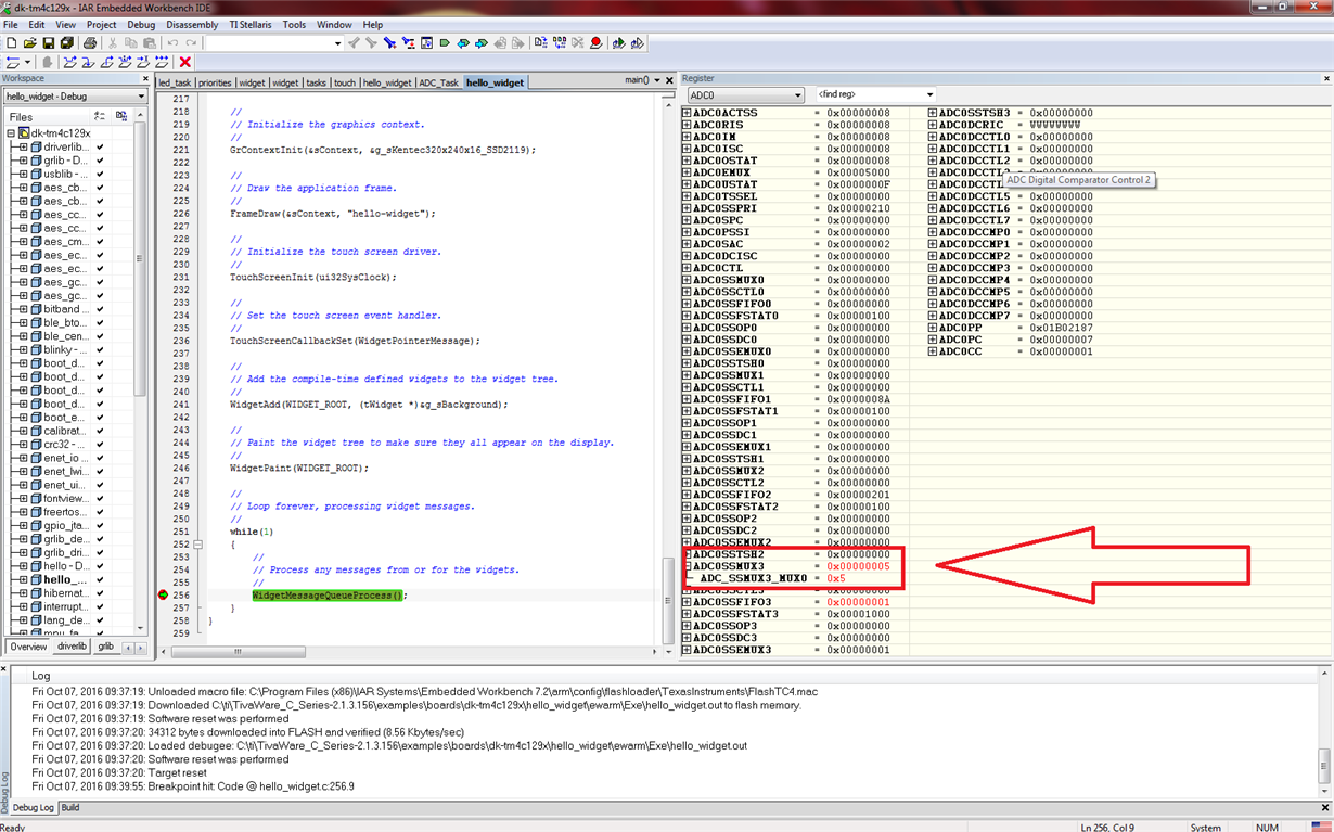
    I guess the register is ADC0SSMUX3 (sequencer 3 of the ADC0), I check it and changes from 0x5 to 0x6 (timer trigger to pwm generator) several times, but in the example of hello_widget does the same.

    Regards.
  • Would it not speed, ease & enhance your troubleshooting of the Touch Screen to enable that code alone - and then consistently touch the same screen location - while closely monitoring the two ADC produced coordinates. For simplicity - I'd "take no action" upon any "Touch Detection" - at this stage you simply want to confirm that the Touch has been recognized by both ADC Channels.

    To do this - you need to create some means to monitor the two ADC Channels - tasked w/reading your touch screen.

    Once that's been achieved - you may slowly, cautiously, systematically add basic Lcd operation - while providing regular touch input (we do that via a small, pneumatic (soft) rubber-button solenoid) which insures a regularly placed Touch Input. At some point - as you add Lcd code - your ADC reporting of "Touch" may be lost - and the "newest added code block" rises to, "Most likely suspect."

    It IS possible that the two ADC channels (still) respond to Touch - yet the "follow on (action part) of your touch code becomes disturbed." Again - close monitoring of what "should" be happening is a sound method for discovering, "Why, where & how" your code is failing.
  • Hi cb1

    I think I didn't write pretty well what I want to achieve, I don't want to make my own library for the touchscreen.
    What I mean to do is to read the signal from two sensors connected to the ADC1 while I use the TI's libraries to control the touchscreen (which uses the ADC0). I can do both things separately but when I want to make them work together as separate tasks with FreeRTOS the touchscreen fails.

    Regards.
  • I was suggesting that you (use) the existing library (maybe w/very slight modification) to "monitor" the success (or not) of the ADC channel reads.

    We understood that you believe the Touchscreen fails - I suggested one means by which you could learn the, "Where & why" of that failure...

    Might it be that "uncritical use/acceptance" of a furnished library (impedes) real understanding? And if so - can that be good?
  • Hello Juan

    That is not correct. The timer must be the source and such changeover should not happen.
  • Hi cb1

    Now I got it jeje sorry, I will see what can I do, because I don't have the equipment you suggest but I'll see what can I do, thanks.
  • Hi juanquique_22
    > I have a task to control the ADC and another for the LCD, both tasks have the same priority.

    Why do assign each sequencer same priority ? my preference would be Screen highest 0 and next trigger priority 1.
    Also (check datasheet) both ADC0/1 (analog block) must be set to use the same clock source configuration.
  • Hi Amit

    Do you know what could be doing that?

    I let you some screenshots

    This is after initialize the touch library

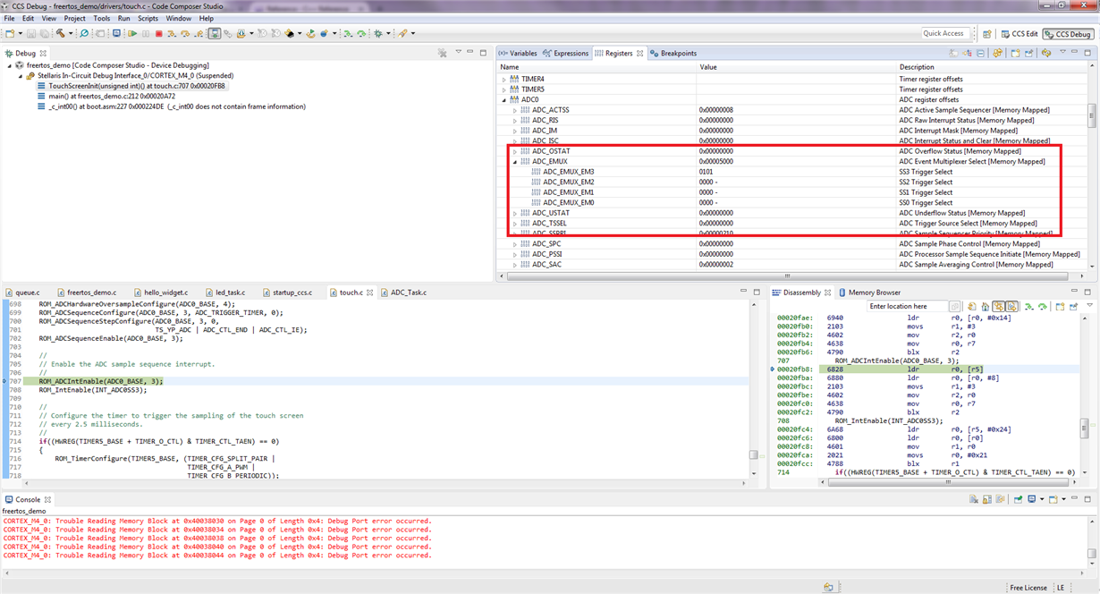
    As you can see the register has the value of 0x6

    After some Go/Pause:


    Some times the value is 0x5 and another is 0x6 and this is from the hello_widget example.

    If you can suggest me more ideas it will be great, by the moment I'll keep doing some tests

    Regards

  • Hello Juan

    Create a HW breakpoint on the register so that when the MCU accesses the register again the program execution halts. That way you will be able to see which code causes the change/update.
  • Hi BP101

    I haven't realized about the priority and I change it. About the clock, I can't find what you say about sharing the same clock source and just in case I didn't initialize in my code (hoping that the clock stays as it's used in the touch library), but still the code doesn't works.
  • Hi,
    If ADC0 was sampling channels so too should ADC1 without need of the clock set. Only mention being FreeRTOS LCD application was working and must have already set ADC analog block clock source.

    Not sure this thread did Amit mention a need to add an ADC trigger initiator to ADC interrupt handler? Perhaps edit your posted source to show you have done did that if so!
  • Hello BP101

    The issue that Juan is facing is that the trigger source is being changed somehow. I have already asked him to put a hardware breakpoint on the Trigger source register access.
  • Hi Amit

    I don't know how to put the hardware breakpoint, do you have a link of how can I do that? or can you explain it please.
  • Hello Juan,

    First launch CCS in debug mode. Once the code is downloaded via CCS, go to View -> Breakpoints

    In the Breakpoint window, right click, then click on Breakpoint (Code Composer Studio) pop up, and go to Hardware Watchpoint. In the location give the 32-bit hex address of the register and in memory select write.
  • Hi Amit,
    >The issue that Juan is facing is that the trigger source is being changed somehow.

    Point was:
    Without RTOS a trigger initiator placed after sequencer set starts a trigger loop and placing a trigger in the INT handler keeps it running but if the sequencer INT is ever missed the loop can end. Installing a processor trigger source initiator in Systick handler might be more reliable and could have missed that in the source listing or posters explanation.
  • Hi Amit

    I'm working on it because I normally work with IAR, give sometime and I let you know what happend.
  • Hi Amit

    I can't install CCS but I find how to make a hardware breakpoint on IAR.
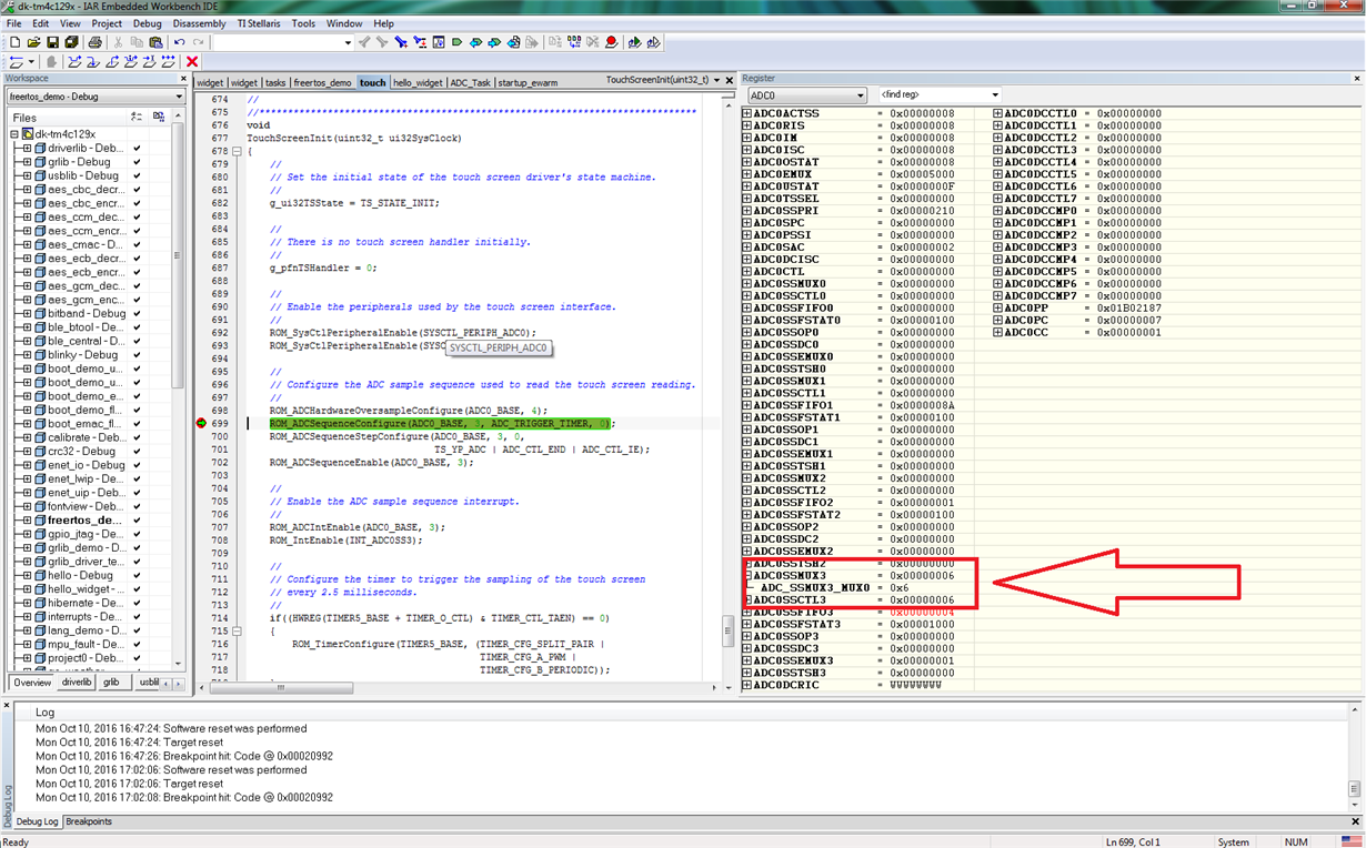
    The code just stops in the call to the function ROM_ADCSequenceConfigure(ADC0_BASE, 3, ADC_TRIGGER_TIMER, 0); in the line 699 of touch.c as expected.
  • Hello Juan

    And that time it gets configured as 0x5 (Timer) and later somehow it gets configured as 0x6 (PWM)?
  • Hi Amit

    Yes it keeps doing that, maybe is a mistake on IAR, maybe the hardware breakpoint is not well implemented on IAR, actually sometimes I get some strangers errors, I don't know if the debugger is bad implemented on the IAR (I don't know a lot about the matter), but well thats a complete different subject.

    If I run the code, IAR stops just after the call to function ROM_ADCSequenceConfigure(); and the register has a value of 0x6

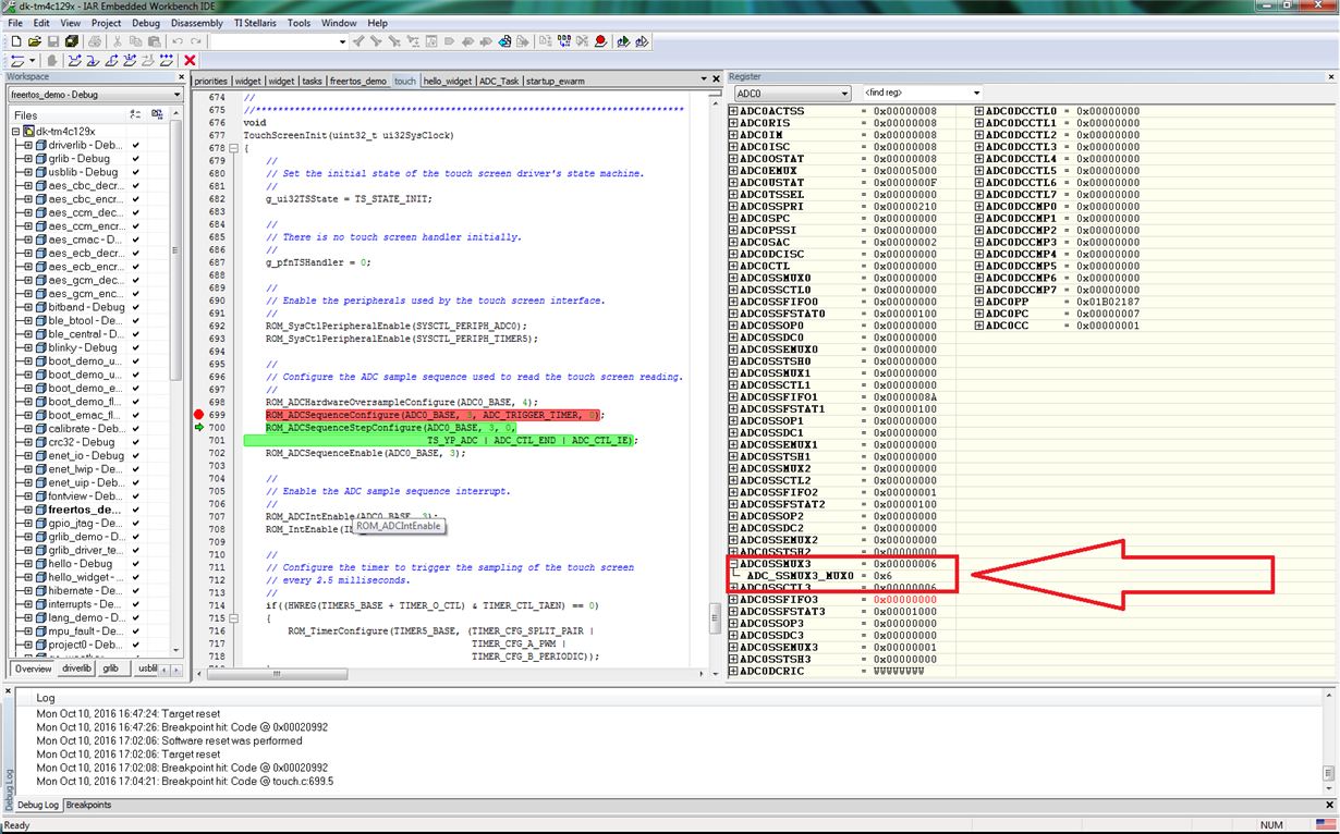
    In the next images I put I break point in the call to the function that wrights to the register and after call it, the value of the register doesn't changes at all.

    After call the function you can see that the register doesn't changes

    I don't know if it is an IAR error, I'm gonna try with CCS again, although I don't like it at all.

  • Hello Juan

    I doubt it is an IAR issue. The debugger should not change the value of a register outside the program scope.
  • Hi Amit

    I put the hardware watchpoint in CCS:

    The program stops at ROM_ADCIntEnable(ADC0_BASE, 3); like you can see in the image, then never stops again.

    Also I pause the program to see the value of the ADCEMUX register and always is 5, even after severals pause/resume always is five, not like IAR that sometimes changes to 6.

    Regards

  • Hello Juan

    I would suggest taking this data up with IAR.
  • Hi Amit

    Ok, I'll keep working with IAR.
    The only possible problem that you see is the change of that register or you have another suggestion? Because to me doesn't look logic, in any part of the code the value is changed or at least that's what IAR/CCS shows.

    Regards and thanks for your appreciated help.
  • Hi Juan,

    Perhaps the trouble (reading error message) may be from not processing interrupts during debug:
    While in Debug: click view/other/debug/ select control panel. On the added control panel check the auto run launch tab has unchecked (interrupts are disabled during run) and maybe try single stepping break points, your choice.

  • Hello Juan

    The ADC touch screen sampler is based on the Timer Trigger. You can confirm by checking that the timer corresponding to the touch screen init routine would be still working with the ADC trigger set.
  • Hi Amit

    The timer isn't either the problem because the code continuously enter to the TouchScreenIntHandler(); what I think that means that the timer always trigger to the sequencer.
    After a time debuggin I watch the values thrown and pass to TouchScreenDebouncer(); by the interrupt handler of the ADC's touch channels, those values are g_i16TouchX; and g_i16TouchY;
    After watch these values several times and press the LCD in several places I realize that the value corresponding to the X axis doesn't change very much like the one corresponding to the Y axis. The X value always stay in low values close to zero while the Y value changes from low values to values near to 4000 (I guess that the limit of the 4096 value of the ADC).
    This happens just with my code, when I run the hello_widget example I can see how both values changes from almost zero to almost 4000, and the values increase when I go down and to the left respectively. In my code just the Y value increase, the X value remains almost zero no matter the position of my finger.
    I guess that the TouchScreenDebouncer(); determines (because of these values) that I'm pressing the screen on an invalid position and doesn't call to the touch handler.

    Now, the question is... Which part of my configuration is causing that the ADC read of the X axis doesn't work properly?

    PD. I haven't test with another boards and I haven't try with another channels (maybe the channnels I'm using make conflict with the ones that the touch library uses although that doesn't sound logic)

    Regards, Juan.
  • Hi cb1

    I follow your advice of see the ADC read of the touchscree in the TI's libraries and I found some interesting things, thanks.

  • Indeed my friend - even a blind squirrel (i.e. this reporter) blunders into an occasional walnut...

    When we "reach" - and/or "assume" things are working - too often we become disappointed. Systematic measurement & confirmation - as part of "test/verify" - always proves helpful. (and in complex projects - must always be employed - even automated...)

    Now to the failure of the "ADC read" of one axis - simple resistive Touch Screens require that a proper voltage be applied across (one) touch screen axis - while the other axis is then "read."   It may be that you are not applying full (or any) voltage to the failing axis - or that the signal IS there - but mis-routed or swallowed by other (unwanted) circuit elements/connections/software alterations!   When my tech firm works w/such resistive Touch Screens we ALWAYS (first) provide a proper, stable voltage to one axis - and then "read" the signal from the other axis.   (I mentioned that we automate this process - via a "soft" linear solenoid (or several) which provides "Known Touch Locations" which enables great confidence in the Touch Screen's performance.)   And can be achieved quickly - while data-logged - for traceability...

    The complication w/these style Touch Screens is that you must be able to "switch" between applying a voltage to each axis - reading the voltage upon the other axis - and then removing that voltage - so that the (past) Voltage Output axis NOW becomes an "Analog Voltage reader."   (i.e. connects to a properly terminated ADC input)

    I agree w/your intent to switch to another ADC Channel and (again) measure - then report.

  • Perhaps a data overflow is occurring in the touch screen (DDA) XY coordinate plane?
    4096 bits is the top of ADC range for 1Msps and 6096 bits for 2Msps when ADC is set full clock 30.
  • Hi cb1

    I don't implement my own hardware yet, I'm testing my code in the TI's development board so doesn't have to be a problem with a bad signal in the ADC of the axis. Because of this I can't change the ADC channels of the axis, I was refering to the channels that I'm using for my own purposes, but still doesn't work.
  • BP101 said:
    Perhaps a data overflow is occurring in the touch screen (DDA) XY coordinate plane?

    May I - w/long experience w/such Touch Screens - comment, "Extremely Unlikely!"

    Here's why - we must assume poster uses or has followed - this vendor's design guide.   The voltage presented sequentially to each axis is MOST UNLIKELY to exceed the ADC's "max Vin" - as that would prove injurious to the MCU's ADC.    Thus - it is without ANY merit to introduce such, "Over-Voltage!"   Further - do we even know how this MCU responds - to an, "Out of Spec, Over-Voltage introduction, to the ADC?"   (Your post argues for an apparent ADC, "wrap" upon over-voltage - yet you present NO/ZERO evidence in support of your theory.)   That's a "reach" - is it not?

    The detailed diagnostic post - presented just prior to this unexplained/unjustified, "REACH" (overflow) - is far more likely to yield insight & lead to success.

  • It just seemed odd the ADC clock is set for 2Msps in source. And compliant of coordinate count stops 4000 just below 4096 and it would seem to me the TScreen might expect 1Msps clock rate not 2Msps clock rate. One has to look at all angles all possibilities otherwise get stuck fighting an invisible gremlin. That's all!
  • BP101 said:
    it would seem to me the TScreen might expect 1Msps clock rate not 2Msps clock rate. One has to look at all angles all possibilities

    Why would TScreen expect 1Msps clock?   Poster clearly reported total success upon one Touch Axis - it (of course) succeeded w/2Msps clock!   You appear to have missed this key fact - did you not?    Critical reading IS important.

    Look at ALL Angles.   Really?   When a clear, direct, diagnostic process is at one's doorstep?   Hardly.

    "Reach" is rarely - if ever - the way...   And looking at all angles is exhausting - even counter-productive - and most always (when the scope of the issue is so small) - NOT required!

  • >Poster clearly reported total success upon one Touch Axis - it (of course) succeeded w/2Msps clock!
     

    Perhaps you missed it was the widget example and that assumes widget example ADC clock is set also to 30Mhz. Again found it odd one axis (variable) in the Tscreen widget posters source locks up upon having an 6096 bit sample ceiling.  So the question was not unfounded in the context being given below as the sample FIFO might easily overflow the array axis variable during reads. As you know interrupt handlers are know killers if code gremlins lead to dysfunction, stack blow up etc..

    The X value always stay in low values close to zero while the Y value changes from low values to values near to 4000 (I guess that the limit of the 4096 value of the ADC). This happens just with my code, when I run the hello_widget example I can see how both values changes from almost zero to almost 4000, and the values increase when I go down and to the left respectively. In my code just the Y value increase, the X value remains almost zero no matter the position of my finger.

  • Are you asking all here to believe that the Touch hardware & software cannot successfully read the X Axis?    Can that (really) be possible?   And passed all of this time - w/out user notice and squawk?    

    It should prove useful for anyone encountering this issue to temporarily "break" the factory/existing connections to the TouchScreen.    Applying 3V3 potential to one axis - while touching the screen - should enable a simple DVM to reveal the voltage upon the 2nd axis.   By changing the location of "touch" that voltage should vary.

    Your final paragraph is most confusing,  you write, "I can see how both values changes from almost zero to almost 4000, and the values increase when I go down and to the left respectively. In my code just the Y value increase, the X value remains almost zero no matter the position of my finger."

    How can you claim: "both values change from almost 0 to 4000" and in the next sentence claim: "the X value remains almost zero?"

    It is good that you've retreated from your (earlier/incorrect) overflow "reach."  

  • Hello Amit

    Any clue of what could be happen with the lecture of the ADC that correspond to the X axis?
    I saw you touch library for your aplication PoE Audio and is pretty much the same that the one that I'm using, except by the TouchScreenInit(); in which one you configure the pins used to drive the touch.
  • Hello Juan

    The basic issue is that for some reason in IAR the value is changing from 0x5 to 0x6 for the trigger source for the ADC, which I can't say for sure as to why it changes.
  • Hello everyone.

    I solved my problem. The issue was that in my ADC initialization I was using the functions ROM_SysCtlPeripheralDisable(SYSCTL_PERIPH_GPIOE); ROM_SysCtlPeripheralReset(SYSCTL_PERIPH_GPIOE); this was causing the problem because the touch uses one pin of the PORT E in analog mode, so first I initialize the touch functionality with the TI's functions where that pin is configured, then I initialize the ADC where I call to the function I mention, reading the User's Guide I realize that PE7 is used and have an special note that says:

    Note: The analog input PE7 (AIN21) is under commit control and extra steps are required in software to enable the function of the pin to be changed, see the "Commit Control" section of the datasheet for more information and the software steps required to enable proper operation of the touch screen.


    So when I disable and reset the PORT E I'm changing the configuration of the PE7 use in the touch control and in specific to the control of the X axis. When I comment those two functions everything works fine.

    Best regards, Juan.

  • Hi Amit

    Me and my partners are using IAR to program TIVAs and we all are having some issues when debugging. When we connect a Tiva for the first time we don't have problems, but after make changes to the code and try to reprogram sometimes the code doesn't stops at the main and starts automatically but without any of the changes we make. I don't know if it's a problem of communication with the tiva that uses of debugger and IAR. Maybe because of that I see changes in the registers that doesn't should happen.
  • Hello Juan

    I would suggest checking with IAR on how to reliably start code execution at main.
  • Hi Amit

    Thanks, I'll check that.

    Regards.
  • Hi Juan,

    Great detective work and most did suspected interference in ADC sequencer as you discovered and later reported. Must say did find it odd source disabled GPIO peripheral prior to enabling. Most often it ends up the wrong ADC channel being input or configuration overwrite in your case. Had similar issue incorrect sample data for over 2 months was actually input yet software filtering made observation difficult and obscure. You discovered and targeted the most obvious area for X-axis failure, concentrated observation found the culprit.  

    Previously reviewed new TI touch screen and wondered how difficult it might be to integrate into existing applications without the RTOS.

    Have any ideas or suggestions? 

  • cb1 said:
    It may be that you are not applying full (or any) voltage to the failing axis - or that the signal IS there - but mis-routed or swallowed by other (unwanted) circuit elements/connections/software alterations!

    Your issue WAS previously identified.   (as the far earlier quote reveals)

    That said - you DID report that "individually" each ADC Touch Axis DID WORK.   As we must assume that PE7 was "equally victimized" then too - this mystery may not have been fully solved.

    One suspects a "Green Verify" was earned by the post which arrived: Thu, Oct 13, 6:02 PM!   That post was "Liked" by you - yet NOT rightfully rewarded!

  • You are right, I was making a software alteration of a signal.
    Thank you.
  • It's fully solved for me.
    If I said that I was wrong, sorry for that.