I'm back with another SPI question.
I am still using the TM4C1294 development board, but this time I am trying to get an external SPI SRAM chip to work. The SRAM being used is a Microchip brand 23LC1024.
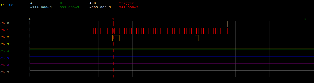
The issue I am having is that the SRAM chip is not sending data back to me under any circumstance. I am not sure if my issue is code or hardware at this point because both seem to follow what I can find every where else on the web. Code and Connections below. I use an oscilloscope on all four lines and I see exactly what i expect sent to the SRAM but that is all.
Any help is appreciated as I am stuck.
Connections to 23LC1024:
Pin 1: CS: Pulled up through 10k resistor, connected to PQ1 on board
Pin2: SO: connected to PQ3
Pin3: connected to 3.3V
Pin4: Vss: connect to ground
Pin5: SI: Connected to PQ2
Pin6: SCK: connected to PQ0
Pin7: connected to Vss Vcc
Pin8: Vss: connected to 3.3V (Edit as Pointed out by Amit)
Pin8: Vcc: connected to 3.3V
//*****************************************************************************
//
// spi_master.c - Example demonstrating how to configure SSI0 in SPI master
//                mode.
//
// Copyright (c) 2010-2015 Texas Instruments Incorporated.  All rights reserved.
// Software License Agreement
//
//   Redistribution and use in source and binary forms, with or without
//   modification, are permitted provided that the following conditions
//   are met:
//
//   Redistributions of source code must retain the above copyright
//   notice, this list of conditions and the following disclaimer.
//
//   Redistributions in binary form must reproduce the above copyright
//   notice, this list of conditions and the following disclaimer in the
//   documentation and/or other materials provided with the
//   distribution.
//
//   Neither the name of Texas Instruments Incorporated nor the names of
//   its contributors may be used to endorse or promote products derived
//   from this software without specific prior written permission.
//
// THIS SOFTWARE IS PROVIDED BY THE COPYRIGHT HOLDERS AND CONTRIBUTORS
// "AS IS" AND ANY EXPRESS OR IMPLIED WARRANTIES, INCLUDING, BUT NOT
// LIMITED TO, THE IMPLIED WARRANTIES OF MERCHANTABILITY AND FITNESS FOR
// A PARTICULAR PURPOSE ARE DISCLAIMED. IN NO EVENT SHALL THE COPYRIGHT
// OWNER OR CONTRIBUTORS BE LIABLE FOR ANY DIRECT, INDIRECT, INCIDENTAL,
// SPECIAL, EXEMPLARY, OR CONSEQUENTIAL DAMAGES (INCLUDING, BUT NOT
// LIMITED TO, PROCUREMENT OF SUBSTITUTE GOODS OR SERVICES; LOSS OF USE,
// DATA, OR PROFITS; OR BUSINESS INTERRUPTION) HOWEVER CAUSED AND ON ANY
// THEORY OF LIABILITY, WHETHER IN CONTRACT, STRICT LIABILITY, OR TORT
// (INCLUDING NEGLIGENCE OR OTHERWISE) ARISING IN ANY WAY OUT OF THE USE
// OF THIS SOFTWARE, EVEN IF ADVISED OF THE POSSIBILITY OF SUCH DAMAGE.
//
// This is part of revision 2.1.1.71 of the Tiva Firmware Development Package.
//
//*****************************************************************************

#include <stdbool.h>
#include <stdint.h>
#include <string.h>
#include <math.h>
#include "inc/hw_memmap.h"
#include "driverlib/gpio.h"
#include "driverlib/pin_map.h"
#include "driverlib/ssi.h"
#include "driverlib/sysctl.h"
#include "driverlib/uart.h"
#include "utils/ustdlib.h"
#include "utils/uartstdio.h"

//*****************************************************************************
//
// This function sets up UART0 to be used for a console to display information
// as the example is running.
//
//*****************************************************************************
void InitConsole(void)
{
    //
    // Enable GPIO port A which is used for UART0 pins.
    // TODO: change this to whichever GPIO port you are using.
    //
    SysCtlPeripheralEnable(SYSCTL_PERIPH_GPIOA);

    //
    // Configure the pin muxing for UART0 functions on port A0 and A1.
    // This step is not necessary if your part does not support pin muxing.
    // TODO: change this to select the port/pin you are using.
    //
    GPIOPinConfigure(GPIO_PA0_U0RX);
    GPIOPinConfigure(GPIO_PA1_U0TX);

    //
    // Enable UART0 so that we can configure the clock.
    //
    SysCtlPeripheralEnable(SYSCTL_PERIPH_UART0);

    //
    // Use the internal 16MHz oscillator as the UART clock source.
    //
    UARTClockSourceSet(UART0_BASE, UART_CLOCK_PIOSC);

    //
    // Select the alternate (UART) function for these pins.
    // TODO: change this to select the port/pin you are using.
    //
    GPIOPinTypeUART(GPIO_PORTA_BASE, GPIO_PIN_0 | GPIO_PIN_1);

    //
    // Initialize the UART for console I/O.
    //
    UARTStdioConfig(0, 115200, 16000000);
}

//*****************************************************************************
//
// Configure SSI0 in master Freescale (SPI) mode.
//
//*****************************************************************************
int main(void)
 {
#if defined(TARGET_IS_TM4C129_RA0) ||                                         \
	defined(TARGET_IS_TM4C129_RA1) ||                                         \
    defined(TARGET_IS_TM4C129_RA2)
	uint32_t ui32SysClock;
#endif

	uint32_t junk = 0;
    uint32_t pui32DataRx  = 0;

    //
    // Set the clocking to run directly from the external crystal/oscillator.
    // TODO: The SYSCTL_XTAL_ value must be changed to match the value of the
    // crystal on your board.
    //
#if defined(TARGET_IS_TM4C129_RA0) ||                                         \
	defined(TARGET_IS_TM4C129_RA1) ||                                         \
    defined(TARGET_IS_TM4C129_RA2)
    ui32SysClock = SysCtlClockFreqSet((SYSCTL_XTAL_25MHZ | SYSCTL_OSC_MAIN |
                                       SYSCTL_USE_OSC), 120000000);
#else
    SysCtlClockSet(SYSCTL_SYSDIV_1 | SYSCTL_USE_OSC | SYSCTL_OSC_MAIN |
                   SYSCTL_XTAL_16MHZ);
#endif

    //
    // Set up the serial console to use for displaying messages.  This is
    // just for this example program and is not needed for SSI operation.
    //
    InitConsole();

    //
    // Display the setup on the console.
    //
    UARTprintf("\033[2J\033[H");
    UARTprintf("SSI ->\n");
    UARTprintf("  Mode: SPI\n");
    UARTprintf("  Data: 16-bit\n\n");

    //
    // The SSI0 peripheral must be enabled for use.
    //
    SysCtlPeripheralEnable(SYSCTL_PERIPH_SSI3);

    //
    // For this example SSI0 is used with PortA[5:2].  The actual port and pins
    // used may be different on your part, consult the data sheet for more
    // information.  GPIO port A needs to be enabled so these pins can be used.
    // TODO: change this to whichever GPIO port you are using.
    //
    SysCtlPeripheralEnable(SYSCTL_PERIPH_GPIOQ);

    //
    // Configure the pin muxing for SSI0 functions on port A2, A3, A4, and A5.
    // This step is not necessary if your part does not support pin muxing.
    // TODO: change this to select the port/pin you are using.
    //
    GPIOPinConfigure(GPIO_PQ0_SSI3CLK);
    GPIOPinTypeGPIOOutput(GPIO_PORTQ_BASE, GPIO_PIN_1); //CS
    GPIOPinConfigure(GPIO_PQ3_SSI3XDAT1);
    GPIOPinConfigure(GPIO_PQ2_SSI3XDAT0);

    //
    // Configure the GPIO settings for the SSI pins.  This function also gives
    // control of these pins to the SSI hardware.  Consult the data sheet to
    // see which functions are allocated per pin.
    // The pins are assigned as follows:
    //      PQ2 - SSI0Tx
    //      PQ3 - SSI0Rx
    //      PQ1 - SSI0Fss
    //      PQ0 - SSI0CLK
    // TODO: change this to select the port/pin you are using.
    //
    GPIOPinTypeSSI(GPIO_PORTQ_BASE, GPIO_PIN_0 | /*GPIO_PIN_1 |*/ GPIO_PIN_2 | GPIO_PIN_3);

    //
    // Configure and enable the SSI port for SPI master mode.  Use SSI0,
    // system clock supply, idle clock level low and active low clock in
    // freescale SPI mode, master mode, 1MHz SSI frequency, and 8-bit data.
    // For SPI mode, you can set the polarity of the SSI clock when the SSI
    // unit is idle.  You can also configure what clock edge you want to
    // capture data on.  Please reference the datasheet for more information on
    // the different SPI modes.
    //
#if defined(TARGET_IS_TM4C129_RA0) ||                                         \
	defined(TARGET_IS_TM4C129_RA1) ||                                         \
    defined(TARGET_IS_TM4C129_RA2)
    SSIConfigSetExpClk(SSI3_BASE, ui32SysClock, SSI_FRF_MOTO_MODE_1,
                       SSI_MODE_MASTER, 10000000, 8);
#else
    SSIConfigSetExpClk(SSI3_BASE, SysCtlClockGet(), SSI_FRF_MOTO_MODE_0,
                       SSI_MODE_MASTER, 1000000, 32);
#endif

    //
    // Enable the SSI0 module.
    //
    SSIEnable(SSI3_BASE);

    //
    // Read any residual data from the SSI port.  This makes sure the receive
    // FIFOs are empty, so we don't read any unwanted junk.  This is done here
    // because the SPI SSI mode is full-duplex, which allows you to send and
    // receive at the same time.  The SSIDataGetNonBlocking function returns
    // "true" when data was returned, and "false" when no data was returned.
    // The "non-blocking" function checks if there is any data in the receive
    // FIFO and does not "hang" if there isn't.
    //
    while(SSIDataGetNonBlocking(SSI3_BASE, &pui32DataRx))
    {
    }

    uint32_t Reset = 0xff;           //0b 1111 1111
    uint32_t write = 0x01;
    uint32_t write_2 = 0x40;
    uint32_t read = 0x05;

	GPIOPinWrite(GPIO_PORTQ_BASE, GPIO_PIN_1, GPIO_PIN_1);
	SysCtlDelay(ui32SysClock / (10) );

	GPIOPinWrite(GPIO_PORTQ_BASE, GPIO_PIN_1, 0);
//	SSIDataPut(SSI3_BASE, Reset);
	SSIDataPut(SSI3_BASE, write);                          //write to write mode register 0x01
	SSIDataPut(SSI3_BASE, write_2);						   //Write the mode 0x40
	SSIDataGet(SSI3_BASE, &junk);						   //Junk reads
	SSIDataGet(SSI3_BASE, &junk);
//	SSIDataGet(SSI3_BASE, &junk);
	GPIOPinWrite(GPIO_PORTQ_BASE, GPIO_PIN_1, GPIO_PIN_1);

	GPIOPinWrite(GPIO_PORTQ_BASE, GPIO_PIN_1, 0);
	SSIDataPut(SSI3_BASE, read);							//write to read mode register 0x05
	SSIDataPut(SSI3_BASE, 0x00);							//Junk write
	SSIDataGet(SSI3_BASE, &junk);							//Junk read, watching osciloscope for responces
	SSIDataGet(SSI3_BASE, &junk);
	GPIOPinWrite(GPIO_PORTQ_BASE, GPIO_PIN_1, GPIO_PIN_1);
	SysCtlDelay(ui32SysClock / (10) );


	while(1)
	{

		//test write to the RAM at memory location 0x000002
		GPIOPinWrite(GPIO_PORTQ_BASE, GPIO_PIN_1, 0);
		SSIDataPut(SSI3_BASE, 0x02);
		SSIDataPut(SSI3_BASE, 0x00);
		SSIDataPut(SSI3_BASE, 0x00);
		SSIDataPut(SSI3_BASE, 0x02);
		SSIDataPut(SSI3_BASE, 0x44);
		SSIDataGet(SSI3_BASE, &junk);
		SSIDataGet(SSI3_BASE, &junk);
		SSIDataGet(SSI3_BASE, &junk);
		SSIDataGet(SSI3_BASE, &junk);
		SSIDataGet(SSI3_BASE, &junk);
		GPIOPinWrite(GPIO_PORTQ_BASE, GPIO_PIN_1, GPIO_PIN_1);

		//test read from RAM at memory location 0x000002
		GPIOPinWrite(GPIO_PORTQ_BASE, GPIO_PIN_1, 0);
		SSIDataPut(SSI3_BASE, 0x03);
		SSIDataPut(SSI3_BASE, 0x00);
		SSIDataPut(SSI3_BASE, 0x00);
		SSIDataPut(SSI3_BASE, 0x02);
		SSIDataPut(SSI3_BASE, 0x00);
		SSIDataGet(SSI3_BASE, &junk);
		SSIDataGet(SSI3_BASE, &junk);
		SSIDataGet(SSI3_BASE, &junk);
		SSIDataGet(SSI3_BASE, &junk);
		SSIDataGet(SSI3_BASE, &junk);
		GPIOPinWrite(GPIO_PORTQ_BASE, GPIO_PIN_1, GPIO_PIN_1);

		//See results on osciloscope but in the event that the string is to long catch it in UART as well
		int i;
		for(i = 0; i < 1; i++)
		{
			UARTprintf("%x", junk);
		}
		UARTprintf("\n");
	}

}