


Hi,
I have a question for the PWM control of TM4C129.
Set the PWM to the up-down mode, the LED will light up. (You can check the ek-tm4c1294xl)
CompA sets the Period value.
While the output of the PWM, it will reduce the value of CompA by one.
Then, the output of the PWM is changed to 0% from the duty ratio of 100%, LED will be black out.
However, if set a 0 to "CompA", it will be full lighting.
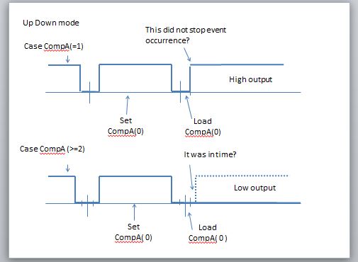
I where it was confirmed, the 1-> 0 and the output to alter the CompA will be next to High,
n-> 0 is varied and CompA Low. (n>=2)
1-> 0 change of only will be High.
1-> 0 change of only will be High.
CompA is 1, the next time is changed to 0, the rise of the PWM would be executed?
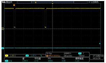
Capture PWM High
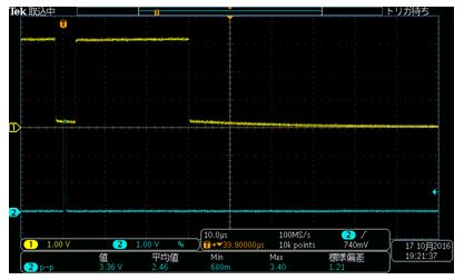
Capture PWM Low
PS
If you want to use the PWMPulseWidthSet (), you can achieve and to increment the width from 0 to Period.
Regards,
Da

