This thread has been locked.

If you have a related question, please click the "Ask a related question" button in the top right corner. The newly created question will be automatically linked to this question.

How many PWM clocks must pwmA pulse width remain above PWMnDBRISE when PWMnDBCTRL enable bit are toggled.

Guru 55913 points
Other Parts Discussed in Thread: LM3S8971, TM4C1294NCPDT, MOTORWARE

TM4C1294i3NCPDT:

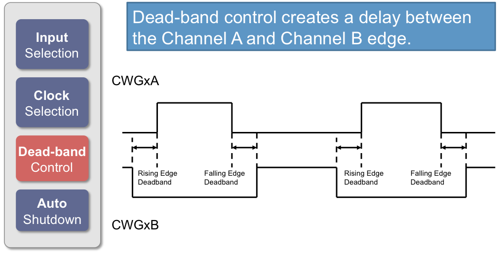
There is a datasheet stated limitation pwmA pulse width must be kept higher than PWMnDBRISE pulse width value at all times.

Ok by how many PWM clocks must pwmA pulse width remain above PWMnDBRISE pulse width when PWM duty cycle is near 100%?

The number of PWM clocks required for setup and propagation delay of signals entering dead band generators is critical when PWMnDBCTRL are being toggled in the duty cycle of pwmA. There are no timing values in table 27.62 to indicate PWMnDBCTRL enable time or PWMnDBRISE being valid PWM clocks when PWMnDBCTRL is toggled at a frequency 8-80 KHz and in this case 80us periods 12.5Khz. Any highly efficient inverter might benefit in light of such disclosure.

There is definitely an undisclosed minimum number PWM clocks required to keep pwmA above PWMnDBRISE. Guessing PWM clocks required can lead to random crashing the PWM generator and poor 1/2 bridge efficiency engineers guess clocks wrong.

  • Complete nonsense never made many the claims as you have suggested in your post. You and others myself included did not understand the so called inversion pwmA to make pwmB is only presented in the edge delay time, not the entire wave form pulse width.

    BTW: Hardware don't give SW the option to selectively enable one dead band generator over another in any single generator. Dead band assigned to any individual PWM generator, both A/B are always activated together. So in fact 2 phases are always receiving dead band delays across any 2 generators in the high to low edge transitions of them, behavior of PWM_GEN_MODE_SYCH.

    The real challenge is can your scope capture the real time edge transition between pwmA and pwmB of any 2 generator blocks. Chances are that is not possible if dead band is working properly. You can see the edges on scope, save them to storage to play back later but capturing the delay of both A/B together very unlikely since the delays are (asynchronous) edges occurring in the synchronous pulse width.
  • Have I not - long past - provided Scope Caps (Video NOT required!) showing independent dead-band control w/in DIFFERENT PWM Generators w/in the SAME PWM Module?

    May I present here and now - for the benefit of you/and (especially) others - a, "Model Code Block" which disproves your "REACH" yet again?

        PWMDeadBandEnable(PWM0_BASE, PWM_GEN_0, 200, 200);
        PWMDeadBandEnable(PWM0_BASE, PWM_GEN_2, 400, 400);   //  minus this call - this PWM Gen may set independent duty cycles across each output

    Such is straight from StellarisWare 9453 (last ver to accommodate (both) LM3S & LX4F)  

    Note that CONTRARY to your claim (yet another BP unjustified, "REACH") Dead Band may INDEED be selectively applied to individual PWM Generators.   The PROOF - minus that 2nd PWMDeadBandEnable() call - that PWM Generator operates correctly w/NO Deadband - enabling independent Duty Cycles!

    Note too that you've (completely) AVOIDED responding to the clear questions past posed!   Your AVOIDANCE is VERY NOTED!

    Why do you believe:

    • PWM_B is "Other than a Slave to PWM_A - when Deadband is enabled.
    • And why you believe Deadband must be "Synced" across multiple (different) PWM Generators.   (especially as only ONE PHASE at a time is deadbanded!)

    In light of this documentation (always absent - your posts) does not your post (above) very well meet your description?   (nonsense)

    As a "model" of (proper) justified SUPPORT for a Technical Claim (thus NOT a "poster REACH") I present Scope Caps - taken w/in the past hour.   (see next post)

  • Our poster claimed that DeadBand INFLICTS UPON ALL Generators w/in a PWM Module Block!   This reporter challenged that (yet another, REACH) presented, as always - with NO/ZERO justification or support.    Such is (at minimum) curious - worse still - it serves to camouflage false advice/guidance!

    Below is a most effective counter to poster's ERRANT, unfounded (minus any justification (beyond hope/reach)) claim!

    DEADBAND IS NOT FORCED UPON EACH/EVERY PWM GENERATOR - MAY BE SELECTIVELY APPLIED!

    Kindly note that (digital) channels "0 & 1" display Deadband.   Channel "0" holds the prescribed duty cycle - Channel 1 is SLAVED to Channel 0 - it may NOT be independently Set when Deadband is enabled!  

    Yet - contrary to our challenging poster's "belief/reach"  NO/ZERO Deadband inflicts upon the 2nd PWM_Generator!   That's proved by their signal overlap - and the ability to independently set duty cycle.   (yet not frequency)

    May we ask, "Why are such MISTAKEN claims made - when SO EASILY DISPROVED - and such data is so "quick/easy" to achieve?   (note too - NO Video is required!)

    DEADBAND HERE IS ENABLED UPON THE (SAME) TWO PWM GENERATORS.   (AS SHOWN ABOVE)

    Here Deadband has been enabled upon BOTH PWM Generators.  (Deadband value has been increased upon the top 2 channels)   Signals, Scope Attachment are exactly the same - only change has been the enabling of the "Call to PWMSetDeadband" for that 2nd PWM Generator - as explained in my post, above.

    House of cards - built upon a very flimsy foundation - occurs when one's "hopes/dreams/REACHES operate outside REALITY!"   Pity that...

    All of the above may be quickly/easily replicated.   Findings were made on (standard) TM4C123 LPad operating under "StellarisWare 9453."   (that's demanded by my firm's clients - newer version does not enjoy the security/robustness of (long) past version...)

  • Oh, lordy. I can go over it in more detail I just didn't think it worth either of our effort since you keep repeating the same nonsense without any foundation.

    BP101 said:
    Actually your signals infer imply center alignment in a (single) PWM generator producing dead band

    (corrected for you)

    They imply no such thing. They are equally valid for either as I have pointed out several times. They are simply the result of the way deadband works.

    BP101 said:
    Your kind of signal is useful in H-bridge power supply design but not 3 phase commutation requiring PWM_GEN_MODE_SYN.

    Stuff and nonsense, it's used for that kind of control pretty well universally.

    BP101 said:
    50ns/cm can not include the falling edge pwmA and 200ns delay could not be witnessed by the human eye at such slow speed.

    But easily seen with an oscilloscope when used by someone who can handle triggering competently. cb1 has shown you captures before and again in this thread. It's quite easily doable. No video, jut a simple trigger. It's even doable with an analog 'scope. A digital 'scope will even give you a fairly easy measure of the jitter. I could have done it with oscilloscopes I have to hand 30 years ago.

    BP101 said:
    The figure below shows a center aligned signal produces a second current pulse configured for

    No. it shows a test waveform and setup used by Infineon/International rectifier to measure shoot through and the energy absorbed in the FET as a result.

    You left off 21c which shows the energy absorbed during the pulse.

    It has nothing to do with TM4Cs and their PWM generators.

    BP101 said:
    The LM3S/TM4C data sheet does not mention generator center alignment becomes distributed between generators in PWM_GEN_MODE_SYNC and should. Might be due to pwmB duty cycle being so high compared to pwmA also contributes to distribution occurring. For that reason pwmA must remain high above PWMnDBRISE to account for the distribution of enabling dead band generators during global synchronous (updates) in the (local updates) of the PWM control block changes sent to the MCU pins in a single itteration. Surely that translates into a specific number of PWM clocks in both SYNC modes. The question how many PWMCLKS in each mode?

    And here I think you are talking out of your hat.

    Robert

    Yes, I did take a swipe at your English. I'm frustrated at your unwillingness to produce coherent understandable prose describing either your measurements or your questions.  An occasional slip-up is understandable but your posts are an exercise in puzzle solving just to determine what you are trying to say. I could understand this if English wasn't your mother tongue but your posts don't seem to follow the grammatical rules that are apparent in non-native speakers either.

  • Robert's rant and grand standing #1.
  • >Hardware don't give SW the option to selectively enable one dead band generator over another in any single generator.

    So you argue against your own argument ? The statement stands true being there are 2 dead band generators to a single PWM generator and they can not be enabled independently. Perhaps you find it hard to understand the obvious, any single generator is taken to mean PWM not dead band.

    >House of cards - built upon a very flimsy foundation - occurs when one's "hopes/dreams/REACHES operate outside REALITY!" Pity that...

    Agree your capture prove little without posted configuration of generators and have no evidence of any dead band cycles occurring. However they show great evidence of center generator alignment, let me guess configured (PWM_GEN_MODE_NO_SYNC)!
    Your being honest to the best of your knowledge base yet others have excelled beyond such nonsense!
  • BP101 said:
    have no evidence of any dead band cycles occurring.

    Really - then your understanding is FAR WORSE than (so many) here believed!

    Look again!  PWMGen0 outputs upon Scope Channels 0,1 below.   And clearly - to all with even the most basic knowledge - Scope's Ch1 is deadband commanded to Ch0.   PWMGen2 - part of the same PWM Module - clearly shows independent PWM operation of each channel - thus is "Free from Deadband."   Which you claimed - (quite WRONGLY) was impossible!    Might it be - instead - that your acceptance of fact - and reality - is impossible?

    You remain "blind to fact" accept only your (own) views - in light of - and especially in light of - massive evidence to the contrary.   I've made time/effort to (correct) your mistaken proclamations - if you cannot accept that there's little (anyone) here can do further.

    The purchase of a sub 50 (USD) board does NOT entitle one to endless, free technical consultation - especially when inappropriate and clearly disproved claims (endlessly) persist.

  • Again disagree CH0 (20us/cm) is not a great way to illustrate the presence of an added dead band delay, your captures prove CH0 center aligns to CH1 (great) now move on!

    *A proper dead band delay resembles 100-360ns period appended onto pwmA/B pulse widths at various times in the duty cycle.  

    For scope to trigger capture a very short blocking delay (100-200ns), the horizontal need be set 50-200ns and probes set across 2 different PWM generator (blocks) pwmA to pwmB and all PWM generators configured (PWM_GEN_MODE_SYNC).

    Otherwise when probes CH0/1 captures on same generator block, scope triggers to a static left aligned pulse width as your first capture seems to prove. Same exact left aligned signal occurs in our scope capture even with PWM_GEN_MODE_SYNC configured to same generator block. The difference in the delay being appended to the period only triggers and shows up across any 2 generator blocks. 

    Months ago posted a capture was told it did not represent proper generator alignment (that was wrong). It was after all an improper persistent dead band delay set to all PWM generator blocks (pwmB) and a highly inefficient inverter results at low side MOS overheating. The bottom pulse changed width to the user (parameter.DeadBandDelay) and no duty cycle changes otherwise occurred, poor engineering results in poor inverter efficiency. Appending the delay to the periods PWMA/B produces much better results as discussed in the TI seminar.

    https://e2e.ti.com/blogs_/b/motordrivecontrol/archive/2016/07/18/what-is-a-smart-gate-drive-architecture-part-2?DCMP=mytinwsltr_09_06_2016&userInfo=gYFWyoPJP8M6lrlW0Ys3xQ==&article_name=hval_mdbu_mdrvblog_motordriver_20160718&newsletter=31-JUL-16&utm_campaign=myTI%20newsletter%202016-09-04&utm_medium=email&utm_source=Eloqua

    No charge for consultation CB1, not so cheep $150 (USD) Motorware RDK and 5 - TM4CXL launch pads!

    Recall this?

  • Just to show the definitions we are using are not unique to

    • cb1 and Robert
    • TI

    This is from microchip.wdfiles.com/.../deadband.png

    Maybe this will be clearer

    Robert

  • BP101 said:
    Again disagree CH0 (20us/cm) is not a great way to illustrate the presence of an added dead band delay, your captures prove CH0 center aligns to CH1 (great) now move on!

    Wrong on both assertions.

    BP101 said:
    For scope to trigger capture a very short blocking delay (100-200ns), the horizontal need be set 50-200ns

    Nope even 500ns/div or quite possibly 1uS/div would show it quite clearly. The latter would depend on the 'scope quality.

    BP101 said:
    probes set across 2 different PWM generator (blocks) pwmA to pwmB

    That might measure something but it would not be deadband.

    And I do remember that screenshot, I also remember you were unable to explain what the traces were.

    Robert

    They are certainly not of deadband.

  • My Rant time!

    Ever consider you and others this forum may still have a few things to learn about PWM peripheral modes of operation? 

    Seems you may believe (Tst) stands for time shoot through, actually stands for Time switching time for both pulses. We don't ever want shoot through to occur from center aligned generator pair, that is the entire point of a dead band delay. Consider second (Id) pulse is reverse current of inductor (turning off) making way back to B+ via external diode clamp (not very effective) and is not relative to the energy produced. The point of posting wave form test was to show the center aligned generator pairs (do not) produce a proper time delay. The generator alignment (GEN_MODE_SYNC) produces left or right edge pairs depending on scope trigger polarity. That is a fact and not consistent with datasheet paragraph vaguely discussing center alignment signal pairs of a single PWM generator.

    BP101
    probes set across 2 different PWM generator (blocks) pwmA to pwmB.
    Robert
    That might measure something but it would not be dead band.
    BP101
    It would be proper probe placement and is dead band measured across two different PWM generator blocks. Data sheet states a center aligned signal pair can be created, Again does not elaborate on all PWM generator configurations. Example SW of dead band delay configures (GEN_MODE_NO_SYNC) for pulse width edge delay to show up on a single generator. Try setting (GEN_MODE_SYNC) and then talk to me about perceived misconceptions of reality. Also don't leave the dead band generators persistently enabled as the delay is properly appended to the active period and not a persistent part of it or the duty cycle update. 
    BP101
    For scope to trigger capture a very short blocking delay (100-200ns), the horizontal need be set 50-200ns
    Robert
    Nope even 500ns/div or quite possibly 1uS/div would show it quite clearly. The latter would depend on the 'scope quality.
    BP101
    The 200ns delayed edge shows up as jitter at 500ns and not (easily) distinguishable by human eye let alone clearly enough for a good capture. Tenma 30Mhz scope has some amazing aspects, such as 1000 frames record and playback of captured wave forms. Believe captured frames can be stored to USB flash stick and played back from the capture file. 
  • BP101 said:
    Seems you may believe (Tst) stands for time shoot through, actually stands for Time switching time

    I seem to recall Infineon calls it time to block but I don't object to calling it switching time. It's the time required to turn off the FET so that current no longer 'shoots through' it.

    BP101 said:
    We don't ever want shoot through to occur from center aligned generator pair

    Alignment is irrelevant. Shoot through occurs from high side to low side of the same phase. It's an uncontrolled short whose current is limited only by parasitics. Between phases there is a rather large motor inductance, the current is effectively constant on the time scales we are talking about.

    BP101 said:
     The point of posting wave form test was to show the center aligned generator pairs (do not) produce a proper time delay.

    You have yet to define what those waveforms are but this explanation is nonsensical

    BP101 said:
    The generator alignment (GEN_MODE_SYNC) produces left or right edge pairs depending on scope trigger polarity. 

    That approaches being surreal. The generator alignment output will not be affected by the 'scope trigger polarity.

    Robert

  • Robert:

    > The generator alignment output will not be affected by the 'scope trigger polarity.

    BP101:

    Yet scope trigger polarity proves claim true and right or left is an arbitrary term relative to only the scopes trigger polarity when pwmA CH1, pwmB CH2. Otherwise if pwmB trigger is opposite pwmA, pwmB then lines up to rising edge of pwmA making them right aligned signal pair. The opposite trigger polarities render left aligned when the datasheet states for 100th time center aligned signals can be generated. Data sheet claim is not the truth in all synch cases or trigger polarity would not matter. Again center alignment occurs only across 2 pwm generator blocks not any single PWM generator block alone.

    Please explain how that occurs if not by (PWM_GEN_MODE_SYNC).?

    Adversely that shifts dead band delay edge positions between 2 generator blocks and can not be captured at any single PWM generator block. 

    Please explain how that occurs if not by (PWM_GEN_MODE_SYNC)?

    Robert:

    Alignment is irrelevant. Shoot through occurs from high side to low side of the same phase. It's an uncontrolled short whose current is limited only by parasitics.

    BP101:

    That's odd it sure seemed to me Robert insisted center aligned signals he posted caused shoot through in the circuit BP101 posted with the very same center aligned signal pair. Now why is that Robert?

    Again point of test circuit was to show center alignment (NO_SYNC) any single H bridge is not proper for 3 phase commutation and will not produce a co-phase partner of opposing gen blocks as does (MODE_SYNC). Believing that (NO_SYNC) will is simply WRONG, that generator mode will not properly commutate a WYE or DELTA stator winding to produce adequate current for rotor displacement.

    After all we both seem to agree shoot through is often disastrous HW condition and must be avoided at all cost even to inverter efficiency losses.

    Engineer need to actually test both SYNC configurations with dead band SW example with 2 PWM gens witness changes between generators or pairs. The dead band SW example is not meant to be taken literally as how dead band should be implemented in all SYNC modes or in all electronic circuit models. We don't ever want to keep dead band generators enabled 100% time, rather append dead delay to the last period in certain cases. Please refer to TI seminar figure 2:

    https://e2e.ti.com/blogs_/b/motordrivecontrol/archive/2016/07/18/what-is-a-smart-gate-drive-architecture-part-2?DCMP=mytinwsltr_09_06_2016&userInfo=gYFWyoPJP8M6lrlW0Ys3xQ==&article_name=hval_mdbu_mdrvblog_motordriver_20160718&newsletter=31-JUL-16&utm_campaign=myTI%20newsletter%202016-09-04&utm_medium=email&utm_source=Eloqua

    That certain case posted 1st capture this thread, delayed edge appended to the end of the last period prior to turning off all inverter FET's. The 33ns gap was the PI integral hunting on either side of the finicky new edge position after dead band disabled via SW. The updates to the wave form has an effect upon gap timing pmwA but did not directly cause shoot through as questioned this thread 1st post.

  • BP101 said:
    Yet scope trigger polarity proves claim true and right or left is an arbitrary term relative to only the scopes trigger polarity when pwmA CH1, pwmB CH2. Otherwise if pwmB trigger is opposite pwmA, pwmB then lines up to rising edge of pwmA making them right aligned signal pair. The opposite trigger polarities render left aligned when the datasheet states for 100th time center aligned signals can be generated. 

    Incomprehensible, I can't parse this in any way that makes sense.

    BP101 said:

    Robert:

    Alignment is irrelevant. Shoot through occurs from high side to low side of the same phase. It's an uncontrolled short whose current is limited only by parasitics.

    BP101:

    That's odd it sure seemed to me Robert insisted center aligned signals he posted caused shoot through in the circuit BP101 posted with the very same center aligned signal pair. Now why is that Robert?

    Nope, never insisted centre aligned signals caused shoot through, I did say what you posted did not demonstrate deadband and if you were measuring the signals that would show deadband the signal would have massive shoot through.

    OTOH, I don't believe you were actually measuring what you were implying you were measuring and you have never explained what the actual signals were that you measured, so I don't think that you did measure dead band which explains why your power devices are still intact..

    BP101 said:
    We don't ever want to keep dead band generators enabled 100% time,

    Seriously? I've yet to see a system that didn't have deadband always enabled. To do otherwise is to invite catastrophe. There is no efficiency gain from turning it off. Even if shoot through did not damage the devices it would cause a large loss in efficiency (high currents, no effect on the motor).

    BP101 said:
    That certain case posted 1st capture this thread, delayed edge appended to the end of the last period prior to turning off all inverter FET's. The 33ns gap was the PI integral hunting on either side of the finicky new edge position after dead band disabled via SW. The updates to the wave form has an effect upon gap timing pmwA but did not directly cause shoot through as questioned this thread 1st post.

    You've yet to show that you can measure deadband much less illustrate a variation in it or to provide software that will illustrate an issue. And the screen captures you presented in this thread do not demonstrate deadband but rather varying duty cycle.

    Both of these should be simple to do but you have done neither.

    Robert

    And the link you gave talks about a system that optimizes the deadband at the cost of gate drive complexity (and possible fragility). Not always an appropriate trade off

  • BP101:
    Yet scope trigger polarity proves claim true and right or left is an arbitrary term relative to only the scopes trigger polarity when pwmA CH1, pwmB CH2. Otherwise if pwmB trigger is opposite pwmA, pwmB then lines up to rising edge of pwmA making them right aligned signal pair. The opposite trigger polarities render left aligned when the datasheet states for 100th time center aligned signals can be generated. What you/others argue being center alignment (GEN_MODE_NO_SYNC) is nonsense when (GEN_MODE_SYNC) is configured. Though pwmA may appear centered pwmB (zoomed out) and only via trigger source pwmB does center alignment occur, otherwise pwmA trigger source produces left/right alignment depending on scope trigger polarity. The active high pulses any individual H bride never align in tandem push/pull (GEN_MODE_SYNC). Again true center alignment occurs across generator blocks with non persistent added dead band cycles. Although a trigger source pwmB aligns center pwmA (GEN_MODE_NO_SYNC) that behavior differs in (GEN_MODE_SYNC). 
    Robert:

    Seriously? I've yet to see a system that didn't have deadband always enabled. To do otherwise is to invite catastrophe. There is no efficiency gain from turning it off. Even if shoot through did not damage the devices it would cause a large loss in efficiency (high currents, no effect on the motor).

    BP101

    Again the TI seminar embodied topic specifically states leaving dead band enabled degrades inverter efficiency. Not only does it degrade inverter efficiency it directly counter acts asserting PWM0 pwmB generator updates if or when left persistently enabled. The point is we only need to enable edge delay across generator blocks during inverter turn off times, thus inserting blanking into the transitions of the duty cycle periods.

    Robert:

    Alignment is irrelevant. Shoot through occurs from high side to low side of the same phase. It's an uncontrolled short whose current is limited only by parasitics.

    BP101:

    Shoot through is controllable via non persistent dead band manipulation and especially in 3 phase context the generator alignment is highly relevant. The 1st capture again shows dead band (appended) to the much wider duty cycle period of a high to low edged transition pwmA.

  • BTW: The strange thing is 3 phase inverters don't use H bridge push/pull pairs per say. Rather a complementary generator block produces an active high for both ends of the phase pair. Perhaps for that reason pwmB dead band delay should not be persistently inverted on the low side. That in theory improves inverter efficiency since pwmB turn on does not always require delay, only prior pwmB ever being turned off append delay. Dead band pwmA is inverted to make pwmB and that edge delay inverts for the remainder of the pulse width period and looks like 1st scope capture.