This thread has been locked.

If you have a related question, please click the "Ask a related question" button in the top right corner. The newly created question will be automatically linked to this question.

Multiple channel ADC using DMA error

Hello everyone, I have configured ADC 0 to read two ADC channels (ADC_CTL_CH0 and ADC_CTL_CH1), one connected to 3.3V and onother connected to GND, I store this information in two buffers using uDMA in ping pong mode. The problem is that in the fourth transfer I get this:

As you can see, the ninth  sample "[8]" of this ping pong DMA buffer is not the correct value that should be readed, It is suppose that I should get a low voltage value. I have configure ADC with DMA like this:

void ADCconfigure(uint32_t sysclock)

{
	SysCtlPeripheralEnable(SYSCTL_PERIPH_GPIOE); 										//Habilita puerto E
    SysCtlPeripheralEnable(SYSCTL_PERIPH_ADC0);
	GPIOPinTypeADC(GPIO_PORTE_BASE, GPIO_PIN_3|GPIO_PIN_2|GPIO_PIN_1); 					//PE3 PE2 PE1 tipo ADC
    SysCtlPeripheralSleepEnable(SYSCTL_PERIPH_ADC0);

    ADCClockConfigSet(ADC0_BASE,ADC_CLOCK_SRC_PIOSC | ADC_CLOCK_RATE_FULL, 1);			//Clock source (Precision Internal Clock)
//  ADCClockConfigSet(ADC0_BASE, ADC_CLOCK_SRC_PLL | ADC_CLOCK_RATE_FULL, 30);

    ADCSequenceConfigure(ADC0_BASE, 0 , ADC_TRIGGER_ALWAYS, 3);  // SS0-SS3 priorities must always be different
    ADCSequenceStepConfigure(ADC0_BASE, 0 , 0, ADC_CTL_CH0);  // ADC_CTL_TS = read temp sensor
    ADCSequenceStepConfigure(ADC0_BASE, 0 , 1, ADC_CTL_CH1);
    ADCSequenceStepConfigure(ADC0_BASE, 0 , 2, ADC_CTL_CH0);
    ADCSequenceStepConfigure(ADC0_BASE, 0 , 3, ADC_CTL_CH1);
    ADCSequenceStepConfigure(ADC0_BASE, 0 , 4, ADC_CTL_CH0);
    ADCSequenceStepConfigure(ADC0_BASE, 0 , 5, ADC_CTL_CH1);
    ADCSequenceStepConfigure(ADC0_BASE, 0 , 6, ADC_CTL_CH0);
    ADCSequenceStepConfigure(ADC0_BASE, 0 , 7, ADC_CTL_CH1 | ADC_CTL_END | ADC_CTL_IE);   // ADC_CTL_IE fires every 8 samples
    ADCSequenceEnable(ADC0_BASE, 0);
    ADCSequenceDMAEnable(ADC0_BASE, 0);

    uDMAChannelAttributeDisable(UDMA_CHANNEL_ADC0,
                                    UDMA_ATTR_ALTSELECT | UDMA_ATTR_USEBURST |
                                    UDMA_ATTR_HIGH_PRIORITY |
                                    UDMA_ATTR_REQMASK);

    uDMAChannelControlSet(UDMA_CHANNEL_ADC0 | UDMA_PRI_SELECT,
                            UDMA_SIZE_16 | UDMA_SRC_INC_NONE | UDMA_DST_INC_16 |
                              UDMA_ARB_1);

    uDMAChannelControlSet(UDMA_CHANNEL_ADC0 | UDMA_ALT_SELECT,
                            UDMA_SIZE_16 | UDMA_SRC_INC_NONE | UDMA_DST_INC_16 |
                              UDMA_ARB_1);

    uDMAChannelTransferSet(UDMA_CHANNEL_ADC0 | UDMA_PRI_SELECT,
                               UDMA_MODE_PINGPONG,
                               (void *)(ADC0_BASE + ADC_O_SSFIFO0),
                               g_ui8RxBufA, MEM_BUFFER_SIZE);

    uDMAChannelTransferSet(UDMA_CHANNEL_ADC0 | UDMA_ALT_SELECT,
                                UDMA_MODE_PINGPONG,
                                (void *)(ADC0_BASE + ADC_O_SSFIFO0),
                                g_ui8RxBufB, MEM_BUFFER_SIZE);
    uDMAChannelEnable(UDMA_CHANNEL_ADC0);
    ADCIntEnableEx(ADC0_BASE, ADC_INT_DMA_SS0);

    IntEnable(INT_ADC0SS0);
 /**/
}

Sequence step configuration is interleaved with ADC_CTL_CH0 and ADC_CTL_CH1, I dont know why always this happens in the fourth DMAs transfer.

Does anyone know why this is happening??, it is related to DMA transfer configuration???

Thanks in advance!!!

  • Hello Josue

    Can you try with the change of the ADC configuration from UDMA_ARB_8 and then try the same?
  • The same happend, at the fourth DMA transfer, I got this

  • Hello Josue

    Instead of using Always trigger can you use the Timer Trigger option and see if the data is read out correctly. I believe the issue is that between the UDMA and CPU, the SRAM is getting bottlenecked so data overflow is happening on the ADC due to continuous trigger.
  • Here is the entire code, it is just DMA transfer for ADC, nothing else is done:

    #include <string.h>
    #include <stdbool.h>
    #include <stdint.h>
    #include <stdio.h>
    #include <stdlib.h>
    
    #include "inc/hw_ints.h"
    #include "driverlib/interrupt.h"
    #include "driverlib/sysctl.h"
    #include "driverlib/systick.h"
    #include "driverlib/rom.h"
    #include "inc/hw_memmap.h"
    #include "driverlib/gpio.h"
    
    #include "driverlib/rom_map.h"
    #include "usblib/usblib.h"
    #include "usblib/usb-ids.h"
    #include "usblib/device/usbdevice.h"
    #include "usblib/device/usbdbulk.h"
    #include "utils/uartstdio.h"
    #include "utils/ustdlib.h"
    //#include "drivers/pinout.h"
    #include "usb_bulk_structs.h"
    
    #include "inc/hw_adc.h"
    #include "inc/hw_types.h"
    #include "inc/hw_udma.h"
    #include "inc/hw_emac.h"
    #include "driverlib/debug.h"
    #include "driverlib/timer.h"
    #include "driverlib/pin_map.h"
    #include "driverlib/rom.h"
    #include "driverlib/uart.h"
    #include "driverlib/adc.h"
    #include "driverlib/udma.h"
    #include "driverlib/emac.h"
    #include "driverlib/pwm.h"
    #include "global_def.h"


    #pragma DATA_ALIGN(pui8ControlTable, 1024)
    uint8_t pui8ControlTable[1024];
    
    #define MEM_BUFFER_SIZE 1024
    static uint16_t g_ui8RxBufA[MEM_BUFFER_SIZE];
    static uint16_t g_ui8RxBufB[MEM_BUFFER_SIZE];
    uint32_t sysclock;
    int aaa;long g = 1; int flag = 0;int ggg;int leFlag = 0;
    
    //*****************************************************************************
    //
    //! \addtogroup adc_examples_list
    //! <h1>Single Ended ADC (single_ended)</h1>
    //!
    
    //*****************************************************************************
    void uDMAErrorHandler(void)
    {
        uint32_t ui32Status;
    
        ui32Status = uDMAErrorStatusGet();	// Check for uDMA error bit
        if(ui32Status)						// If there is a uDMA error
        {
            uDMAErrorStatusClear();			//Clear the error status
        }
    
    }
    //*****************************************************************************
    void ADCseq0Handler()
    
    {
    
    	uint32_t ui32Status = ADCIntStatus(ADC0_BASE, 0, false);
        uint32_t ui32Mode;
        ROM_ADCIntClear(ADC0_BASE, 0);						//se puede eliminar
        ADCIntClearEx(ADC0_BASE, ADC_INT_DMA_SS0);
        ui32Mode = uDMAChannelModeGet(UDMA_CHANNEL_ADC0 | UDMA_PRI_SELECT);
    
        if(ui32Mode == UDMA_MODE_STOP & leFlag == 0)
        {
            uDMAChannelTransferSet(UDMA_CHANNEL_ADC0 | UDMA_PRI_SELECT,
                                       UDMA_MODE_PINGPONG,
                                       (void *)(ADC0_BASE + ADC_O_SSFIFO0),
                                       g_ui8RxBufA, MEM_BUFFER_SIZE);
            flag++;
            leFlag = 1; //---------------------------> BreakPoint here
        }
        ui32Mode = uDMAChannelModeGet(UDMA_CHANNEL_ADC0 | UDMA_ALT_SELECT);
    
    
        if(ui32Mode == UDMA_MODE_STOP & leFlag == 1)
    
        {
            uDMAChannelTransferSet(UDMA_CHANNEL_ADC0 | UDMA_ALT_SELECT,
                                        UDMA_MODE_PINGPONG,
                                        (void *)(ADC0_BASE + ADC_O_SSFIFO0),
                                        g_ui8RxBufB, MEM_BUFFER_SIZE);
            flag++;
            leFlag = 0;  /------------------------------>Break point here
        }
        uDMAChannelEnable(UDMA_CHANNEL_ADC0);
    }
    
    //*****************************************************************************
    void InitConsole(void)											/*Configuracion de periferico UART*/
    {
        SysCtlPeripheralEnable(SYSCTL_PERIPH_GPIOA);				// Habilitacion de periferico GPIOA
        GPIOPinConfigure(GPIO_PA0_U0RX);							// Configurar pin PA0 para recepción
        GPIOPinConfigure(GPIO_PA1_U0TX);							// Configurar pin PA0 para transmision
        SysCtlPeripheralEnable(SYSCTL_PERIPH_UART0);				// Habilita periferico UART0
        UARTClockSourceSet(UART0_BASE, UART_CLOCK_SYSTEM);			// Fuente de Clock para uart sacada del clock del sistema 120MHz
        GPIOPinTypeUART(GPIO_PORTA_BASE, GPIO_PIN_0 | GPIO_PIN_1);  // PA0 y PA1 tipo UART
    //  UARTStdioConfig(0, 115200, 120000000);
        UARTConfigSetExpClk(UART0_BASE
        					,sysclock				     			//Fuente de señal de Configurar pin PA0 para recepciónConfigurar pin PA0 para recepciónclock
    						,115200									//Baud rate
    						,(UART_CONFIG_WLEN_8					//Longitud de trama 8 bits
    						 |UART_CONFIG_STOP_ONE					//Un bit de stop
    						 |UART_CONFIG_PAR_NONE));				//No hay bit de paridad
    }
    //*****************************************************************************
    
    void ADCconfigure(uint32_t sysclock)
    
    {
    	SysCtlPeripheralEnable(SYSCTL_PERIPH_GPIOE); 										//Habilita puerto E
        SysCtlPeripheralEnable(SYSCTL_PERIPH_ADC0);
    	GPIOPinTypeADC(GPIO_PORTE_BASE, GPIO_PIN_3|GPIO_PIN_2|GPIO_PIN_1); 					//PE3 PE2 PE1 tipo ADC
        SysCtlPeripheralSleepEnable(SYSCTL_PERIPH_ADC0);
    
        ADCClockConfigSet(ADC0_BASE,ADC_CLOCK_SRC_PIOSC | ADC_CLOCK_RATE_FULL, 1);			//Clock source (Precision Internal Clock)
    //  ADCClockConfigSet(ADC0_BASE, ADC_CLOCK_SRC_PLL | ADC_CLOCK_RATE_FULL, 30);
    
        ADCSequenceConfigure(ADC0_BASE, 0 /*SS0*/, ADC_TRIGGER_ALWAYS, 3 /*priority*/);  // SS0-SS3 priorities must always be different
        ADCSequenceStepConfigure(ADC0_BASE, 0 /*SS0*/, 0, ADC_CTL_CH0);  // ADC_CTL_TS = read temp sensor
        ADCSequenceStepConfigure(ADC0_BASE, 0 /*SS0*/, 1, ADC_CTL_CH1);
        ADCSequenceStepConfigure(ADC0_BASE, 0 /*SS0*/, 2, ADC_CTL_CH0);
        ADCSequenceStepConfigure(ADC0_BASE, 0 /*SS0*/, 3, ADC_CTL_CH1);
        ADCSequenceStepConfigure(ADC0_BASE, 0 /*SS0*/, 4, ADC_CTL_CH0);
        ADCSequenceStepConfigure(ADC0_BASE, 0 /*SS0*/, 5, ADC_CTL_CH1);
        ADCSequenceStepConfigure(ADC0_BASE, 0 /*SS0*/, 6, ADC_CTL_CH0);
        ADCSequenceStepConfigure(ADC0_BASE, 0 /*SS0*/, 7, ADC_CTL_CH1 | ADC_CTL_END | ADC_CTL_IE);   // ADC_CTL_IE fires every 8 samples
        ADCSequenceEnable(ADC0_BASE, 0);
        ADCSequenceDMAEnable(ADC0_BASE, 0);
    
        uDMAChannelAttributeDisable(UDMA_CHANNEL_ADC0,
                                        UDMA_ATTR_ALTSELECT | UDMA_ATTR_USEBURST |
                                        UDMA_ATTR_HIGH_PRIORITY |
                                        UDMA_ATTR_REQMASK);
    
        uDMAChannelControlSet(UDMA_CHANNEL_ADC0 | UDMA_PRI_SELECT,
                                UDMA_SIZE_16 | UDMA_SRC_INC_NONE | UDMA_DST_INC_16 |
                                  UDMA_ARB_8);
    
        uDMAChannelControlSet(UDMA_CHANNEL_ADC0 | UDMA_ALT_SELECT,
                                UDMA_SIZE_16 | UDMA_SRC_INC_NONE | UDMA_DST_INC_16 |
                                  UDMA_ARB_8);
    
        uDMAChannelTransferSet(UDMA_CHANNEL_ADC0 | UDMA_PRI_SELECT,
                                   UDMA_MODE_PINGPONG,
                                   (void *)(ADC0_BASE + ADC_O_SSFIFO0),
                                   g_ui8RxBufA, MEM_BUFFER_SIZE);
    
        uDMAChannelTransferSet(UDMA_CHANNEL_ADC0 | UDMA_ALT_SELECT,
                                    UDMA_MODE_PINGPONG,
                                    (void *)(ADC0_BASE + ADC_O_SSFIFO0),
                                    g_ui8RxBufB, MEM_BUFFER_SIZE);
        uDMAChannelEnable(UDMA_CHANNEL_ADC0);
        ADCIntEnableEx(ADC0_BASE, ADC_INT_DMA_SS0);
        IntEnable(INT_ADC0SS0);
    }
    
    int main(void)
    
    {
         sysclock = SysCtlClockFreqSet((SYSCTL_XTAL_25MHZ |
                                          SYSCTL_OSC_MAIN |
                                           SYSCTL_USE_PLL |
                            SYSCTL_CFG_VCO_480), 120000000);
         aaa = 2;
         InitConsole();
         ROM_SysCtlPeripheralEnable(SYSCTL_PERIPH_GPION);    						// Enable the GPIO port that is used for the on-board LED.
         ROM_SysCtlPeripheralEnable(SYSCTL_PERIPH_GPIOF);
         ROM_GPIOPinTypeGPIOOutput(GPIO_PORTF_BASE, GPIO_PIN_0 | GPIO_PIN_4);
         ROM_GPIOPinTypeGPIOOutput(GPIO_PORTN_BASE, GPIO_PIN_0);    					// Enable the GPIO pins for the LED (PN0).
         ROM_GPIOPinTypeGPIOOutput(GPIO_PORTN_BASE, GPIO_PIN_1);    					// Enable the GPIO pins for the LED (PN0).
         g++;
         SysCtlPeripheralEnable(SYSCTL_PERIPH_UDMA);g++;
         SysCtlPeripheralSleepEnable(SYSCTL_PERIPH_UDMA);g++;
         IntMasterEnable();g++;
         IntEnable(INT_UDMAERR);g++;
         uDMAEnable();g++;
         uDMAControlBaseSet(pui8ControlTable);g++;
         ADCconfigure(sysclock);g++;


        while(1)
        {
    
        }
    
    }
    

    I use break points to analize the information (they are indicated in the code).

  • Hi Amit, my goal is to achieve the 2MSPS, using Timer Trigger will help me to achieve it???, and how???, I have heard also about using PWM to get fixed sampled rates.
  • Hello Josue

    To achieve the 2MSPS sampling rate, the clock for the ADC has to be set as the 32MHz. It takes 16 clocks for sampling and storing the data, so 32MHz/16 = 2MSPS. Now the trigger always option is the best method, but in order to find the cause of the issue, I would first suggest using a timer to trigger the ADC at 100KHz and see if the issue occurs.
  • I have implememted the ADC with DMA using timmer trigering, the code works, but I dont know if the configuration is correct:

    #include <string.h>
    #include <stdbool.h>
    #include <stdint.h>
    #include <stdio.h>
    #include <stdlib.h>
    
    #include "inc/hw_ints.h"
    #include "driverlib/interrupt.h"
    #include "driverlib/sysctl.h"
    #include "driverlib/systick.h"
    #include "driverlib/rom.h"
    #include "inc/hw_memmap.h"
    #include "driverlib/gpio.h"
    
    #include "driverlib/rom_map.h"
    #include "usblib/usblib.h"
    #include "usblib/usb-ids.h"
    #include "usblib/device/usbdevice.h"
    #include "usblib/device/usbdbulk.h"
    #include "utils/uartstdio.h"
    #include "utils/ustdlib.h"
    #include "usb_bulk_structs.h"
    
    #include "inc/hw_adc.h"
    #include "inc/hw_types.h"
    #include "inc/hw_udma.h"
    #include "inc/hw_emac.h"
    #include "driverlib/debug.h"
    #include "driverlib/pin_map.h"
    #include "driverlib/rom.h"
    #include "driverlib/uart.h"
    #include "driverlib/adc.h"
    #include "driverlib/udma.h"
    #include "driverlib/emac.h"
    #include "driverlib/pwm.h"
    #include "global_def.h"
    
    #include "driverlib/fpu.h"
    #include "driverlib/timer.h"
    
    #pragma DATA_ALIGN(pui8ControlTable, 1024)
    uint8_t pui8ControlTable[1024];
    
    #define MEM_BUFFER_SIZE 1024
    static uint16_t g_ui8RxBufA[MEM_BUFFER_SIZE];
    static uint16_t g_ui8RxBufB[MEM_BUFFER_SIZE];
    uint32_t sysclock;
    int aaa;long g = 1; int flag = 0;int ggg;int leFlag = 0; int error = 0;
    volatile uint16_t valorErradoA = 2;
    volatile uint16_t valorErradoB = 2;
    uint32_t g_ui32Flags;
    //*****************************************************************************
    //
    //! \addtogroup adc_examples_list
    //! <h1>Single Ended ADC (single_ended)</h1>
    //!
    
    //*****************************************************************************
    void uDMAErrorHandler(void)
    {
        uint32_t ui32Status;
    
        ui32Status = uDMAErrorStatusGet();	// Check for uDMA error bit
        if(ui32Status)						// If there is a uDMA error
        {
            uDMAErrorStatusClear();			//Clear the error status
        }
    
    }
    //*****************************************************************************
    void ADCseq0Handler()
    
    {
        TimerDisable(TIMER0_BASE, TIMER_A);
    	uint32_t ui32Status = ADCIntStatus(ADC0_BASE, 0, false);
        uint32_t ui32Mode;
        ROM_ADCIntClear(ADC0_BASE, 0);						//se puede eliminar
        ADCIntClearEx(ADC0_BASE, ADC_INT_DMA_SS0);
        ui32Mode = uDMAChannelModeGet(UDMA_CHANNEL_ADC0 | UDMA_PRI_SELECT);
    
        if(ui32Mode == UDMA_MODE_STOP & leFlag == 0)
        {
            uDMAChannelTransferSet(UDMA_CHANNEL_ADC0 | UDMA_PRI_SELECT,
                                       UDMA_MODE_PINGPONG,
                                       (void *)(ADC0_BASE + ADC_O_SSFIFO0),
                                       g_ui8RxBufA, MEM_BUFFER_SIZE);
    
            valorErradoA = g_ui8RxBufA[0];
            if(valorErradoA > 2000)
            {
            	error = flag;
            }
    
            flag++;
            leFlag = 1;
    
        }
        ui32Mode = uDMAChannelModeGet(UDMA_CHANNEL_ADC0 | UDMA_ALT_SELECT);
    
    
        if(ui32Mode == UDMA_MODE_STOP & leFlag == 1)
    
        {
            uDMAChannelTransferSet(UDMA_CHANNEL_ADC0 | UDMA_ALT_SELECT,
                                        UDMA_MODE_PINGPONG,
                                        (void *)(ADC0_BASE + ADC_O_SSFIFO0),
                                        g_ui8RxBufB, MEM_BUFFER_SIZE);
            valorErradoB = g_ui8RxBufB[0];
            if(valorErradoB > 2000)
            {
            	error = flag;
            }
            flag++;
            leFlag = 0;
    
        }
        uDMAChannelEnable(UDMA_CHANNEL_ADC0);
        TimerEnable(TIMER0_BASE, TIMER_A);
    }
    
    //*****************************************************************************
    
    void ADCconfigure(uint32_t sysclock)
    
    {
    	SysCtlPeripheralEnable(SYSCTL_PERIPH_GPIOE); 										//Habilita puerto E
        SysCtlPeripheralEnable(SYSCTL_PERIPH_ADC0);
    	GPIOPinTypeADC(GPIO_PORTE_BASE, GPIO_PIN_3|GPIO_PIN_2|GPIO_PIN_1); 					//PE3 PE2 PE1 tipo ADC
        SysCtlPeripheralSleepEnable(SYSCTL_PERIPH_ADC0);
    
        ADCClockConfigSet(ADC0_BASE,ADC_CLOCK_SRC_PIOSC | ADC_CLOCK_RATE_FULL, 1);			//Clock source (Precision Internal Clock)
    //  ADCClockConfigSet(ADC0_BASE, ADC_CLOCK_SRC_PLL | ADC_CLOCK_RATE_FULL, 30);
    
        ADCSequenceConfigure(ADC0_BASE, 0 /*SS0*/, ADC_TRIGGER_TIMER, 3 /*priority*/);  // SS0-SS3 priorities must always be different
        ADCSequenceStepConfigure(ADC0_BASE, 0 /*SS0*/, 0, ADC_CTL_CH0);  // ADC_CTL_TS = read temp sensor
        ADCSequenceStepConfigure(ADC0_BASE, 0 /*SS0*/, 1, ADC_CTL_CH1);
        ADCSequenceStepConfigure(ADC0_BASE, 0 /*SS0*/, 2, ADC_CTL_CH0);
        ADCSequenceStepConfigure(ADC0_BASE, 0 /*SS0*/, 3, ADC_CTL_CH1);
        ADCSequenceStepConfigure(ADC0_BASE, 0 /*SS0*/, 4, ADC_CTL_CH0);
        ADCSequenceStepConfigure(ADC0_BASE, 0 /*SS0*/, 5, ADC_CTL_CH1);
        ADCSequenceStepConfigure(ADC0_BASE, 0 /*SS0*/, 6, ADC_CTL_CH0);
        ADCSequenceStepConfigure(ADC0_BASE, 0 /*SS0*/, 7, ADC_CTL_CH1 | ADC_CTL_END | ADC_CTL_IE);   // ADC_CTL_IE fires every 8 samples
        ADCSequenceEnable(ADC0_BASE, 0);
        ADCSequenceDMAEnable(ADC0_BASE, 0);
    
        uDMAChannelAttributeDisable(UDMA_CHANNEL_ADC0,
                                        UDMA_ATTR_ALTSELECT | UDMA_ATTR_USEBURST |
                                        UDMA_ATTR_HIGH_PRIORITY |
                                        UDMA_ATTR_REQMASK);
    
        uDMAChannelControlSet(UDMA_CHANNEL_ADC0 | UDMA_PRI_SELECT,
                                UDMA_SIZE_16 | UDMA_SRC_INC_NONE | UDMA_DST_INC_16 |
                                  UDMA_ARB_8);
    
        uDMAChannelControlSet(UDMA_CHANNEL_ADC0 | UDMA_ALT_SELECT,
                                UDMA_SIZE_16 | UDMA_SRC_INC_NONE | UDMA_DST_INC_16 |
                                  UDMA_ARB_8);
    
        uDMAChannelTransferSet(UDMA_CHANNEL_ADC0 | UDMA_PRI_SELECT,
                                   UDMA_MODE_PINGPONG,
                                   (void *)(ADC0_BASE + ADC_O_SSFIFO0),
                                   g_ui8RxBufA, MEM_BUFFER_SIZE);
    
        uDMAChannelTransferSet(UDMA_CHANNEL_ADC0 | UDMA_ALT_SELECT,
                                    UDMA_MODE_PINGPONG,
                                    (void *)(ADC0_BASE + ADC_O_SSFIFO0),
                                    g_ui8RxBufB, MEM_BUFFER_SIZE);
        uDMAChannelEnable(UDMA_CHANNEL_ADC0);
        ADCIntEnableEx(ADC0_BASE, ADC_INT_DMA_SS0);
        IntEnable(INT_ADC0SS0);
    //--------------------------------------------------------------------
        SysCtlPeripheralEnable(SYSCTL_PERIPH_TIMER0);
        TimerConfigure(TIMER0_BASE, TIMER_CFG_A_PERIODIC);
        TimerLoadSet(TIMER0_BASE, TIMER_A, sysclock/1200);
        TimerControlTrigger(TIMER0_BASE, TIMER_A, true);
        TimerEnable(TIMER0_BASE, TIMER_A);
    
    }
    
    int main(void)
    
    {
         sysclock = SysCtlClockFreqSet((SYSCTL_XTAL_25MHZ |
                                          SYSCTL_OSC_MAIN |
                                           SYSCTL_USE_PLL |
                            SYSCTL_CFG_VCO_480), 120000000);
    
         SysCtlPeripheralEnable(SYSCTL_PERIPH_UDMA);
         SysCtlPeripheralSleepEnable(SYSCTL_PERIPH_UDMA);
         IntEnable(INT_UDMAERR);
         uDMAEnable();
         uDMAControlBaseSet(pui8ControlTable);
    
         ADCconfigure(sysclock);
    /**/
    
         IntMasterEnable();
    
        while(1)
        {
    
        }
    
    }
    

    I dont know if it is OK to disable and enable the TIMER in lines 74 and 118, without this, the code does not work. The ADC's trigger is working at 100KHz.

    Thanks in advance!!!

  • Hello Josue

    There is no need to disable and enable the timer. This is because the buffer switch over by the DMA would take care of the intermediate period. Now increase the frequency of the trigger to see at what point does the buffer fail, which will help us isolate the region of failure.
  • Hello Amit, I have realized about this problem because I was communicating the MCU with my PC by USB, I have modified my original adquisition code to make the next test:

    1)  The Host (PC) generates data to the MCU, every time the MCU receives from the host the char 'a', the MCU passes the information of 1024 ADC samples to the USB buffer using DMA.

    2) 1000 times the host generates 100 times the char 'a' to get the ADC information from the MCU (1000*100*1024 ADC values).

    3) After this is done, the MCU modifies the load value from the TIMER by using a divider that increase its value by 1000, the initial value of the divider is 40000, and the last value is 51000. In other words the experiment was repeated 12 times with 12 diferent load values for the TIMER:

    sysclock = 120000000;


    TimerLoadSet(TIMER0_BASE, TIMER_A, sysclock/divider);

    This are the results:

    DIvider Load Value (120000000/Divider) Quantity of errors
    40000 3000.0 0
    41000 2926.8 0
    42000 2857.1 0
    43000 2790.7 0
    44000 2727.3 100
    45000 2666.7 100
    46000 2608.7 200
    47000 2553.2 2800
    48000 2500.0 4300
    49000 2449.0 6300
    50000 2400.0 11500
    51000 2352.9 17700

    ADC 0 is enabled, two ADC channel are readed:

    ADCSequenceConfigure(ADC0_BASE, 0 , ADC_TRIGGER_TIMER, 3);
    ADCSequenceStepConfigure(ADC0_BASE, 0 , 0, ADC_CTL_CH0);
    ADCSequenceStepConfigure(ADC0_BASE, 0 , 1, ADC_CTL_CH1);
    ADCSequenceStepConfigure(ADC0_BASE, 0 , 2, ADC_CTL_CH0);
    ADCSequenceStepConfigure(ADC0_BASE, 0 , 3, ADC_CTL_CH1);
    ADCSequenceStepConfigure(ADC0_BASE, 0 , 4, ADC_CTL_CH0);
    ADCSequenceStepConfigure(ADC0_BASE, 0 , 5, ADC_CTL_CH1);
    ADCSequenceStepConfigure(ADC0_BASE, 0 , 6, ADC_CTL_CH0);
    ADCSequenceStepConfigure(ADC0_BASE, 0 , 7, ADC_CTL_CH1 | ADC_CTL_END | ADC_CTL_IE); 

    ADC_CTL_CH0 is connected to GND and ADC_CTL_CH1 is connected to 3.3v, so for example, once the CH0 reads a high voltage (3.3V), an error is registered, this is how errors are detected.

  • Amit can you explain me a little more about the problem with the SRAM and how TIMER triggering solves it and why always triggering no?? Also, this modification looks like solves the problem, but it has reduce the speed transmission of the USB in 1Mbps, because when I was using Always trigger I have achieved 5.5 Mbps aprox, now using the Timer trigering the speed has decreases to 4.3Mbps aprox using a 40000 divider. In this order, it will be impossible to achieve 2MSPS???

    I will solve the speed transfer problem with the USB3300

  • Hello Josue

    When the CPU is processing USB information, it is storing and retrieving volatile parameters and flags in the SRAM. This is the same SRAM where the DMA is also transferring the data.

    Upto 43KHz trigger rate there are no errors. But above that there are errors accumulating.

    1. if the CPU is checking the same while additional transfers are happening, then it is the wrong approach. The ADC and Timer must be stopped when checking the captured value. Once check is performed then it should start the next set of captures.

    As given in the following TI Design

    www.ti.com/.../TIDM-TM4C129POEAUDIO

    I am using 48KHz trigger for the ADC along with DMA and I do not see an issue.
  • The problem for me was perceptible only while using two ADC channels (with two very diferent voltage values), using only one channel the problem will not be perceptible. I have found the error while using USB, but the same problem apears on a simple ADC DMA code, without USB, I detect this using the debugger and break points.

  • Hello Josue,

    Let me try the same on my setup with 2 ADC channels and timer trigger to see what is the maximum throughput that can be achieved, without an error.
  • Hello Amit, using 3 ADC channel is worst, 40000 Hz is not enough....
    please, try with 3 channels
  • Hello Josue,

    I would try to keep the code simple and straight when there is a known failure point.
  • Amit, Using a simple ADC code, without DMA and USB a similar problem appears, here is the code:

    #include <string.h>
    #include <stdbool.h>
    #include <stdint.h>
    #include <stdio.h>
    #include <stdlib.h>
    
    #include "inc/hw_ints.h"
    #include "driverlib/interrupt.h"
    #include "driverlib/sysctl.h"
    #include "driverlib/systick.h"
    #include "driverlib/rom.h"
    #include "inc/hw_memmap.h"
    #include "driverlib/gpio.h"
    
    #include "driverlib/rom_map.h"
    #include "usblib/usblib.h"
    #include "usblib/usb-ids.h"
    #include "usblib/device/usbdevice.h"
    #include "usblib/device/usbdbulk.h"
    #include "utils/uartstdio.h"
    #include "utils/ustdlib.h"
    #include "usb_bulk_structs.h"
    
    #include "inc/hw_adc.h"
    #include "inc/hw_types.h"
    #include "inc/hw_udma.h"
    #include "inc/hw_emac.h"
    #include "driverlib/debug.h"
    #include "driverlib/pin_map.h"
    #include "driverlib/rom.h"
    #include "driverlib/uart.h"
    #include "driverlib/adc.h"
    #include "driverlib/udma.h"
    #include "driverlib/emac.h"
    #include "driverlib/pwm.h"
    #include "global_def.h"
    
    #include "driverlib/fpu.h"
    #include "driverlib/timer.h"
    
    #define F_SAMPLE 1000
    
    uint32_t InputBuffer[4];
    
    void ADC0IntHandler(void)
    {
        ADCIntClear(ADC0_BASE, 2);
        ADCSequenceDataGet(ADC0_BASE, 2, InputBuffer);
    }
    void main(void)
    {
        SysCtlPeripheralReset(SYSCTL_PERIPH_ADC0);
        SysCtlPeripheralReset(SYSCTL_PERIPH_TIMER0);
        SysCtlClockSet(SYSCTL_SYSDIV_10 | SYSCTL_USE_PLL | SYSCTL_OSC_MAIN |
                           SYSCTL_XTAL_16MHZ);
        SysCtlPeripheralEnable(SYSCTL_PERIPH_TIMER0);
    
       
        SysCtlPeripheralEnable(SYSCTL_PERIPH_ADC0); 
        SysCtlDelay(10);
        SysCtlPeripheralEnable(SYSCTL_PERIPH_GPIOE);
        GPIOPinTypeADC(GPIO_PORTE_BASE, GPIO_PIN_2 | GPIO_PIN_3); 
        IntDisable(INT_ADC0SS2);
        ADCIntDisable(ADC0_BASE, 2);
        ADCSequenceDisable(ADC0_BASE, 2);
        ADCSequenceConfigure(ADC0_BASE, 2, ADC_TRIGGER_ALWAYS, 0);
    
        ADCSequenceStepConfigure(ADC0_BASE, 2, 0, ADC_CTL_CH0);
        ADCSequenceStepConfigure(ADC0_BASE, 2, 1, ADC_CTL_CH1);
        ADCSequenceStepConfigure(ADC0_BASE, 2, 2, ADC_CTL_CH0);
        ADCSequenceStepConfigure(ADC0_BASE, 2, 3, ADC_CTL_CH1 | ADC_CTL_IE |ADC_CTL_END);
    
        ADCSequenceEnable(ADC0_BASE, 2);
        ADCIntClear(ADC0_BASE, 2);
        ADCIntEnable(ADC0_BASE, 2);
        IntEnable(INT_ADC0SS2);
    
        IntMasterEnable(); // Enable processor interrupts
    
        while(1)
        {
        }
    }

    It looks like the problem is only related with the ADC and it's configuration, this code is nor using TIMERS, but it is just ADC without DMA!!!! 

    which could be the problem?
  • Hello Josue

    CPU read is going to be slower than ADC read due to the instructions that need to be processed when going to the Interrupt Handler and then reading it from the ADC Data register. I would be very sure that the FIFO Overflow flags would have been set.
  • So therer is a similar prblen with or without DMA, what should be done to get the correct ADC values, timer are a solución, but with them 1 or 2 MSPS  would be imposible to achieve ...

  • I am talking abouth reading the correct ADC values from diferentes Analog sources using one ADC channel , In this case ADC ch 0, i really nead those 1 Msps per ADC channel, with this problem i will not be able to eecognize from where the diferente voltage values come from. One more thing, the first read, using or not using DMA is correct, only the first read.

  • Hello Josue,

    I agree. That is why I am devising an experiment to isolate the issue first.
  • This code use Always trigger, and dont make any mistake, this only works with SS3,SS2 and SS1.

    SS0 is not working yet:

    #include <string.h>
    #include <stdbool.h>
    #include <stdint.h>
    #include <stdio.h>
    #include <stdlib.h>
    
    #include "inc/hw_ints.h"
    #include "driverlib/interrupt.h"
    #include "driverlib/sysctl.h"
    #include "driverlib/systick.h"
    #include "driverlib/rom.h"
    #include "inc/hw_memmap.h"
    #include "driverlib/gpio.h"
    
    #include "driverlib/rom_map.h"
    #include "usblib/usblib.h"
    #include "usblib/usb-ids.h"
    #include "usblib/device/usbdevice.h"
    #include "usblib/device/usbdbulk.h"
    #include "utils/uartstdio.h"
    #include "utils/ustdlib.h"
    #include "usb_bulk_structs.h"
    
    #include "inc/hw_adc.h"
    #include "inc/hw_types.h"
    #include "inc/hw_udma.h"
    #include "inc/hw_emac.h"
    #include "driverlib/debug.h"
    #include "driverlib/pin_map.h"
    #include "driverlib/rom.h"
    #include "driverlib/uart.h"
    #include "driverlib/adc.h"
    #include "driverlib/udma.h"
    #include "driverlib/emac.h"
    #include "driverlib/pwm.h"
    #include "global_def.h"
    
    #include "driverlib/fpu.h"
    #include "driverlib/timer.h"
    
    #define F_SAMPLE 1000
    
    uint32_t InputBuffer[4];
    uint32_t ui32SysClock;
    uint32_t error = 0;
    uint32_t status;
    
    
    void ADC0IntHandler(void)
    {
    	while(ADCIntStatus(ADC0_BASE, 2, false))
    	    {
    
        	ADCIntDisable(ADC0_BASE, 2);
    	    ADCSequenceDataGet(ADC0_BASE, 2, InputBuffer);
    	    if (InputBuffer[0] > 2000)
    			{
    				error++;
    			}
    	    ADCIntClear(ADC0_BASE, 2);
    		ADCIntEnable(ADC0_BASE, 2);
    
    	    }
    }
    void main(void)
    {
    
    
        ui32SysClock = SysCtlClockFreqSet((SYSCTL_XTAL_25MHZ |
                                           SYSCTL_OSC_MAIN |
                                           SYSCTL_USE_PLL |
                                           SYSCTL_CFG_VCO_480), 120000000);
    
        SysCtlPeripheralEnable(SYSCTL_PERIPH_ADC0);
        SysCtlDelay(10);
        SysCtlPeripheralEnable(SYSCTL_PERIPH_GPIOE);
        GPIOPinTypeADC(GPIO_PORTE_BASE, GPIO_PIN_0 | GPIO_PIN_1 | GPIO_PIN_2 | GPIO_PIN_3);
        IntDisable(INT_ADC0SS2);
        ADCIntDisable(ADC0_BASE, 2);
        ADCSequenceDisable(ADC0_BASE, 2);
        ADCSequenceConfigure(ADC0_BASE, 2, ADC_TRIGGER_ALWAYS, 0);
    
        ADCSequenceStepConfigure(ADC0_BASE, 2, 0, ADC_CTL_CH0);
        ADCSequenceStepConfigure(ADC0_BASE, 2, 1, ADC_CTL_CH1);
        ADCSequenceStepConfigure(ADC0_BASE, 2, 2, ADC_CTL_CH2);
        ADCSequenceStepConfigure(ADC0_BASE, 2, 3, ADC_CTL_CH3 | ADC_CTL_IE |ADC_CTL_END);
    
        ADCSequenceEnable(ADC0_BASE, 2);
        ADCIntClear(ADC0_BASE, 2);
        ADCIntEnable(ADC0_BASE, 2);
        IntEnable(INT_ADC0SS2);
    
        IntMasterEnable(); // Enable processor interrupts
    
        ADCSequenceDataGet(ADC0_BASE, 2, InputBuffer);
    
    
        while(1)
        {
        }
    }

  • The last code i said that works, does not really works, it was an illusion created by using break points. The problem persist, the only method that stored ADC information correctly is PROCESOR TRIGGER, but I do not know if it will work using DMA. I am still working on this.....
  • Hello Josue

    I have run the following code at 48KHz sampling rate from a timer and the ADC does not fail a single time. This contradicts the earlier timer experiment you ran. I also a lot of inconsistency in the code, so I have simplified the same.

    4532.main.c
    #include <string.h>
    #include <stdbool.h>
    #include <stdint.h>
    #include <stdio.h>
    #include <stdlib.h>
    
    #include "inc/hw_ints.h"
    #include "driverlib/interrupt.h"
    #include "driverlib/sysctl.h"
    #include "driverlib/systick.h"
    #include "driverlib/rom.h"
    #include "inc/hw_memmap.h"
    #include "driverlib/gpio.h"
    
    #include "driverlib/rom_map.h"
    
    #include "inc/hw_adc.h"
    #include "inc/hw_types.h"
    #include "inc/hw_udma.h"
    #include "inc/hw_emac.h"
    #include "driverlib/debug.h"
    #include "driverlib/pin_map.h"
    #include "driverlib/rom.h"
    #include "driverlib/uart.h"
    #include "driverlib/adc.h"
    #include "driverlib/udma.h"
    #include "driverlib/emac.h"
    #include "driverlib/pwm.h"
    
    #include "driverlib/fpu.h"
    #include "driverlib/timer.h"
    
    #pragma DATA_ALIGN(pui8ControlTable, 1024)
    uint8_t pui8ControlTable[1024];
    
    #define MEM_BUFFER_SIZE 1024
    static uint16_t g_ui8RxBufA[MEM_BUFFER_SIZE];
    static uint16_t g_ui8RxBufB[MEM_BUFFER_SIZE];
    uint32_t sysclock;
    int aaa;long g = 1; int flag = 0;int ggg;int leFlag = 0; int error = 0;
    volatile uint16_t valorErradoA = 2;
    volatile uint16_t valorErradoB = 2;
    uint32_t g_ui32Flags;
    //*****************************************************************************
    //
    //! \addtogroup adc_examples_list
    //! <h1>Single Ended ADC (single_ended)</h1>
    //!
    
    //*****************************************************************************
    void uDMAErrorHandler(void)
    {
        uint32_t ui32Status;
    
        ui32Status = uDMAErrorStatusGet();	// Check for uDMA error bit
        if(ui32Status)						// If there is a uDMA error
        {
            uDMAErrorStatusClear();			//Clear the error status
        }
    
    }
    //*****************************************************************************
    void ADCseq0Handler(void)
    
    {
    	uint16_t ui16Index;
    
        TimerDisable(TIMER0_BASE, TIMER_A);
    	uint32_t ui32Status = ADCIntStatus(ADC0_BASE, 0, false);
        uint32_t ui32Mode;
        ROM_ADCIntClear(ADC0_BASE, 0);						//se puede eliminar
        ADCIntClearEx(ADC0_BASE, ADC_INT_DMA_SS0);
        ui32Mode = uDMAChannelModeGet(UDMA_CHANNEL_ADC0 | UDMA_PRI_SELECT);
    
        if(ui32Mode == UDMA_MODE_STOP)
        {
            uDMAChannelTransferSet(UDMA_CHANNEL_ADC0 | UDMA_PRI_SELECT,
                                       UDMA_MODE_PINGPONG,
                                       (void *)(ADC0_BASE + ADC_O_SSFIFO0),
                                       g_ui8RxBufA, MEM_BUFFER_SIZE);
    
            for(ui16Index=0;ui16Index<MEM_BUFFER_SIZE;ui16Index++)
            {
            	if((g_ui8RxBufA[ui16Index] < 2000) && (ui16Index%2 == 0))
            	{
            		flag++;
            	}
            	if((g_ui8RxBufA[ui16Index] > 2000) && (ui16Index%2 == 1))
            	{
            		flag++;
            	}
            }
    
        }
        ui32Mode = uDMAChannelModeGet(UDMA_CHANNEL_ADC0 | UDMA_ALT_SELECT);
    
    
        if(ui32Mode == UDMA_MODE_STOP)
    
        {
            uDMAChannelTransferSet(UDMA_CHANNEL_ADC0 | UDMA_ALT_SELECT,
                                        UDMA_MODE_PINGPONG,
                                        (void *)(ADC0_BASE + ADC_O_SSFIFO0),
                                        g_ui8RxBufB, MEM_BUFFER_SIZE);
            for(ui16Index=0;ui16Index<MEM_BUFFER_SIZE;ui16Index++)
            {
            	if((g_ui8RxBufA[ui16Index] < 2000) && (ui16Index%2 == 0))
            	{
            		flag++;
            	}
            	if((g_ui8RxBufA[ui16Index] > 2000) && (ui16Index%2 == 1))
            	{
            		flag++;
            	}
            }
    
        }
        uDMAChannelEnable(UDMA_CHANNEL_ADC0);
        TimerEnable(TIMER0_BASE, TIMER_A);
    }
    
    //*****************************************************************************
    
    void ADCconfigure(uint32_t sysclock)
    
    {
    	SysCtlPeripheralEnable(SYSCTL_PERIPH_GPIOE); 										//Habilita puerto E
        SysCtlPeripheralEnable(SYSCTL_PERIPH_ADC0);
    	GPIOPinTypeADC(GPIO_PORTE_BASE, GPIO_PIN_3|GPIO_PIN_2|GPIO_PIN_1); 					//PE3 PE2 PE1 tipo ADC
        SysCtlPeripheralSleepEnable(SYSCTL_PERIPH_ADC0);
    
        ADCClockConfigSet(ADC0_BASE,ADC_CLOCK_SRC_PIOSC | ADC_CLOCK_RATE_FULL, 1);			//Clock source (Precision Internal Clock)
    //  ADCClockConfigSet(ADC0_BASE, ADC_CLOCK_SRC_PLL | ADC_CLOCK_RATE_FULL, 30);
    
        ADCSequenceConfigure(ADC0_BASE, 0 /*SS0*/, ADC_TRIGGER_TIMER, 3 /*priority*/);  // SS0-SS3 priorities must always be different
        ADCSequenceStepConfigure(ADC0_BASE, 0 /*SS0*/, 0, ADC_CTL_CH0);  // ADC_CTL_TS = read temp sensor
        ADCSequenceStepConfigure(ADC0_BASE, 0 /*SS0*/, 1, ADC_CTL_CH1);
        ADCSequenceStepConfigure(ADC0_BASE, 0 /*SS0*/, 2, ADC_CTL_CH0);
        ADCSequenceStepConfigure(ADC0_BASE, 0 /*SS0*/, 3, ADC_CTL_CH1);
        ADCSequenceStepConfigure(ADC0_BASE, 0 /*SS0*/, 4, ADC_CTL_CH0);
        ADCSequenceStepConfigure(ADC0_BASE, 0 /*SS0*/, 5, ADC_CTL_CH1);
        ADCSequenceStepConfigure(ADC0_BASE, 0 /*SS0*/, 6, ADC_CTL_CH0);
        ADCSequenceStepConfigure(ADC0_BASE, 0 /*SS0*/, 7, ADC_CTL_CH1 | ADC_CTL_END | ADC_CTL_IE);   // ADC_CTL_IE fires every 8 samples
        ADCSequenceEnable(ADC0_BASE, 0);
        ADCSequenceDMAEnable(ADC0_BASE, 0);
    
        uDMAChannelAttributeDisable(UDMA_CHANNEL_ADC0,
                                        UDMA_ATTR_ALTSELECT | UDMA_ATTR_USEBURST |
                                        UDMA_ATTR_HIGH_PRIORITY |
                                        UDMA_ATTR_REQMASK);
    
        uDMAChannelControlSet(UDMA_CHANNEL_ADC0 | UDMA_PRI_SELECT,
                                UDMA_SIZE_16 | UDMA_SRC_INC_NONE | UDMA_DST_INC_16 |
                                  UDMA_ARB_8);
    
        uDMAChannelControlSet(UDMA_CHANNEL_ADC0 | UDMA_ALT_SELECT,
                                UDMA_SIZE_16 | UDMA_SRC_INC_NONE | UDMA_DST_INC_16 |
                                  UDMA_ARB_8);
    
        uDMAChannelTransferSet(UDMA_CHANNEL_ADC0 | UDMA_PRI_SELECT,
                                   UDMA_MODE_PINGPONG,
                                   (void *)(ADC0_BASE + ADC_O_SSFIFO0),
                                   g_ui8RxBufA, MEM_BUFFER_SIZE);
    
        uDMAChannelTransferSet(UDMA_CHANNEL_ADC0 | UDMA_ALT_SELECT,
                                    UDMA_MODE_PINGPONG,
                                    (void *)(ADC0_BASE + ADC_O_SSFIFO0),
                                    g_ui8RxBufB, MEM_BUFFER_SIZE);
        uDMAChannelEnable(UDMA_CHANNEL_ADC0);
        ADCIntEnableEx(ADC0_BASE, ADC_INT_DMA_SS0);
        IntEnable(INT_ADC0SS0);
    //--------------------------------------------------------------------
        SysCtlPeripheralEnable(SYSCTL_PERIPH_TIMER0);
        TimerConfigure(TIMER0_BASE, TIMER_CFG_A_PERIODIC);
        TimerLoadSet(TIMER0_BASE, TIMER_A, sysclock/48000);
        TimerControlTrigger(TIMER0_BASE, TIMER_A, true);
        TimerEnable(TIMER0_BASE, TIMER_A);
    
    }
    
    int main(void)
    
    {
         sysclock = SysCtlClockFreqSet((SYSCTL_XTAL_25MHZ |
                                          SYSCTL_OSC_MAIN |
                                           SYSCTL_USE_PLL |
                            SYSCTL_CFG_VCO_480), 120000000);
    
         SysCtlPeripheralEnable(SYSCTL_PERIPH_UDMA);
         SysCtlPeripheralSleepEnable(SYSCTL_PERIPH_UDMA);
         IntEnable(INT_UDMAERR);
         uDMAEnable();
         uDMAControlBaseSet(pui8ControlTable);
    
         ADCconfigure(sysclock);
    /**/
    
         IntMasterEnable();
    
        while(1)
        {
    
        }
    
    }
    

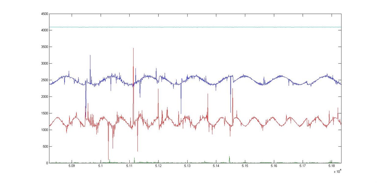
  • Hi Amit, like you said, everything was OK, my original code that triggers the ADC with a Timer was also OK, everything works fine .This is the result of the adquisition of 4 ADC channels, now I have to work on the interference:

    Thank you very much for your help!!!!

  • Hello Josue

    Make sure you have a good Low Pass Filter for noise filtering and the input impedance of the ADC is matched.