This thread has been locked.

If you have a related question, please click the "Ask a related question" button in the top right corner. The newly created question will be automatically linked to this question.

My ADC code

Other Parts Discussed in Thread: LM3S3748

Hello I am using Stellaris lm3s3748 and all i want is to read a signal from the ADC0 and after the conversion i wanna write the output to GPIO PA0 as digital output i wrote the code but am not sure that its the correct way i want someone to help me if there any issue in my code
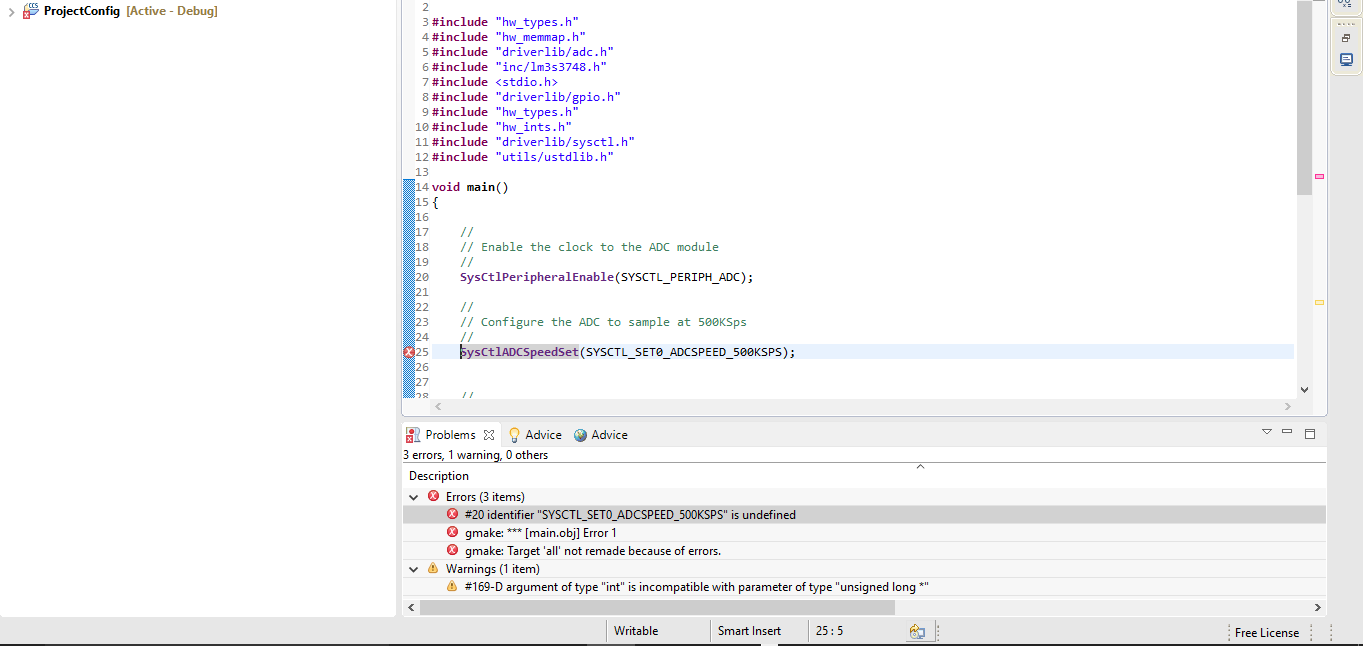
this is my code


#include "hw_types.h"
#include "hw_memmap.h"
#include "driverlib/adc.h"
#include "inc/lm3s3748.h"
#include <stdio.h>
#include "driverlib/gpio.h"
#include "hw_types.h"
#include "hw_ints.h"
#include "driverlib/sysctl.h"
#include "utils/ustdlib.h"

void main()
{

//
//
//Turn ADC module ON
//
//
SYSCTL_RCGC0_R |= SYSCTL_RCGC0_ADC;

//
//Sampling frequency set 500ksps
//
SYSCTL_RCGC0_R |= SYSCTL_RCGC0_ADCSPD500K;

//
// Disable the ADC for safe modification
//
ADC_ACTSS_R &= ~(ADC_ACTSS_ASEN0);
while(1){
//
//
//if there is any ADC process, give the priority to Sample sequencer 0 (the sequencer that I use) --optional
//
ADC_SSPRI_R = (ADC_SSPRI_SS0_1ST);

//
//
// ADC module trigger is the processor
//
ADC_EMUX_R = (ADC_EMUX_EM0_PROCESSOR);


//
//
//Configure pin ADC0 as an input
//
//
ADC_SSMUX0_R = ((0 << ADC_SSMUX0_MUX0_S));

//
// Retrieve data from sample sequence 0 FIFO invariable X1
//
//
int x1 = ADC_SSFIFO0_R;

//enable GPIO portA
SysCtlPeripheralEnable(SYSCTL_PERIPH_GPIOA);
//Configure pin PA0 as an output
GPIODirModeSet(GPIO_PORTA_BASE, 0x01, GPIO_DIR_MODE_OUT);
//write variable x1 to pin PA0
GPIOPinWrite(GPIO_PORTA_BASE, 0x01, x1);

}
}


thanks in advance

  • Hello Mohammad,

    Please use StellarisWare API instead of DRM. It is tough knowing if all steps for enabling ADC input, ADC module and the digital IO are correctly done.
  • Hi 

    this is the ADC code using API 

    #include "hw_types.h"
    #include "hw_memmap.h"
    #include "driverlib/adc.h"
    #include "inc/lm3s3748.h"
    #include <stdio.h>
    #include "driverlib/gpio.h"
    #include "hw_types.h"
    #include "hw_ints.h"
    #include "driverlib/sysctl.h"
    #include "utils/ustdlib.h"

    void main()
    {

    //
    // Enable the clock to the ADC module
    //
    SysCtlPeripheralEnable(SYSCTL_PERIPH_ADC);

    //
    // Configure the ADC to sample at 500KSps
    //
    SysCtlADCSpeedSet(SYSCTL_SET0_ADCSPEED_500KSPS);


    //
    // Disable sample sequences 0
    //
    ADCSequenceDisable(ADC_BASE, 0);

    //
    // Configure sample sequence 0 step 0
    //
    ADCSequenceStepConfigure(ADC_BASE, 0, 0, ADC_CTL_CH0);

    //
    // Retrieve data from sample sequence 0 FIFO
    //
    int x1=0;
    while(1){
    ADCSequenceDataGet(ADC_BASE, 0, x1);

    //enable GPIO portA
    SysCtlPeripheralEnable(SYSCTL_PERIPH_GPIOA);
    //Configure pin PA0 as an output
    GPIODirModeSet(GPIO_PORTA_BASE, 0x01, GPIO_DIR_MODE_OUT);
    //write variable x1 to pin PA0
    GPIOPinWrite(GPIO_PORTA_BASE, 0x01, x1);

    }
    }

    but errors occurred shown in the snapshot below

    please advice thank you

  • Hello Mohammad

    The parameter is SYSCTL_ADCSPEED_500KSPS and not SYSCTL_SET0_ADCSPEED_500KSPS
  • Thank you Amit the ADC speed API worked, but I want to know if the code functions the LM3S3748 the way I described, I'd appreciate it if can clarify 

    Regards
  • Hello Mohammad

    No, it will not work as the ADC Sequencer has not been enabled, End of sequence has not been set and quite a few of them. That is hwy I referred to the example code in the other post.
  • Poster would benefit from LM3S example, "Single-ended ADC" w/in examples/peripherals/adc.
  • Hi Amit thank you for help the below is my new code 

    i am concern with the output coming just from one pin (PA0)  is that right or i have to write the output to multiple pins if so how its done, and can you please explain the SysCtlDelay(SysCtlClockGet() / 12); function and if it is necessary

    thanks in advance   

    #include "hw_types.h"
    #include "hw_memmap.h"
    #include "driverlib/adc.h"
    #include "inc/lm3s3748.h"
    #include <stdio.h>
    #include "driverlib/gpio.h"
    #include "hw_types.h"
    #include "hw_ints.h"
    #include "driverlib/sysctl.h"
    #include "utils/ustdlib.h"

    void main()
    {
    unsigned long ADC0Value[1];
    // CLK for LM3S3748 16MHz for Phase Lock Loop
    SysCtlClockSet(SYSCTL_SYSDIV_10 | SYSCTL_USE_PLL | SYSCTL_OSC_MAIN | SYSCTL_XTAL_16MHZ);
    //ENABLE ADC0 PORT TO BE CONFIGURED
    SysCtlPeripheralEnable(SYSCTL_PERIPH_ADC0);
    //ENABLE GPIO PORT-A0 (PA0/U0RX) TO BE CONFIGURED
    SysCtlPeripheralEnable(SYSCTL_PERIPH_GPIOA);
    //SPECIFY PORT-A0 (PA0/U0RX) TO WORK WITH THE ADC MODULE
    GPIOPinTypeADC(GPIO_PORTA_BASE, GPIO_PIN_0);
    //CONFIGURE SAMPLE SEQUENCER 3 STEP 0 TO RUN WHEN THE PROCESSOR IS TRIGGERED
    ADCSequenceConfigure(ADC0_BASE, 3, ADC_TRIGGER_PROCESSOR, 0);
    //CONFIGURE PIN ADC0, SET INTERRAUPT FLAG WHEN ADC IS DONE, TELL THE ADC IT'S THE LAST CONVERSION IN SEQUENCER 3
    ADCSequenceStepConfigure(ADC0_BASE, 3, 0, ADC_CTL_CH0 | ADC_CTL_IE | ADC_CTL_END);
    //AFTER CONFIGURATION IS DONE, ENABLE THE ADC MODULE
    ADCSequenceEnable(ADC0_BASE, 3);
    //CLEAR INTERRUPT FLAG ON SEQUENCE 3
    ADCIntClear(ADC0_BASE, 3);


    //FOREVER LOOP
    while(1)
    {
    //TRIGGER ADC
    ADCProcessorTrigger(ADC0_BASE, 3);
    //WAIT UNTILL THE CONVERSION IS FINISHED
    while(!ADCIntStatus(ADC0_BASE, 3, false))
    {}
    //CLEAR INTERRUPT FLAG
    ADCIntClear(ADC0_BASE, 3);
    //RETRIVE ADC FIFO RESULT
    ADCSequenceDataGet(ADC0_BASE, 3, ADC0Value);
    //SET GPIO PIN A0 AS AN OUTPUT
    GPIODirModeSet(GPIO_PORTA_BASE, 0x01, GPIO_DIR_MODE_OUT);
    //WRITE ADC RESULT TO PIN PA0
    GPIOPinWrite(GPIO_PORTA_BASE, 0x01,ADC0Value[0]);

    SysCtlDelay(SysCtlClockGet() / 12);
    }
    }

  • Hello Mohammad

    You would need to write the value to 12 GPIO's. BTW what is the sink device for the values being sent?
  • Hi Amit thank you for your reply
    1- how do I write the output to 12 pins
    2- I want to send the values to SIM5320A 3G module

    Thanks in advance
  • Hello Mohammad

    I am not an expert for SIM5320A 3G module. I believe the communication between SIM and a uC is via UART. So effectively you would need to use the UART to send data, though the format is not clear to me.
  • Thanks for your efforts Amit I'll try the UART communication.
  • Hello Mohammad

    Please check the SIM datasheet on the method for data exchange.
  • Hi Amit I checked the Method is UART so I will use UART as communication
    Thank you