This thread has been locked.

If you have a related question, please click the "Ask a related question" button in the top right corner. The newly created question will be automatically linked to this question.

Connect XDS100v3 to EK-TM4C1294XL

Other Parts Discussed in Thread: TM4C1294NCPDT, EK-TM4C1294XL

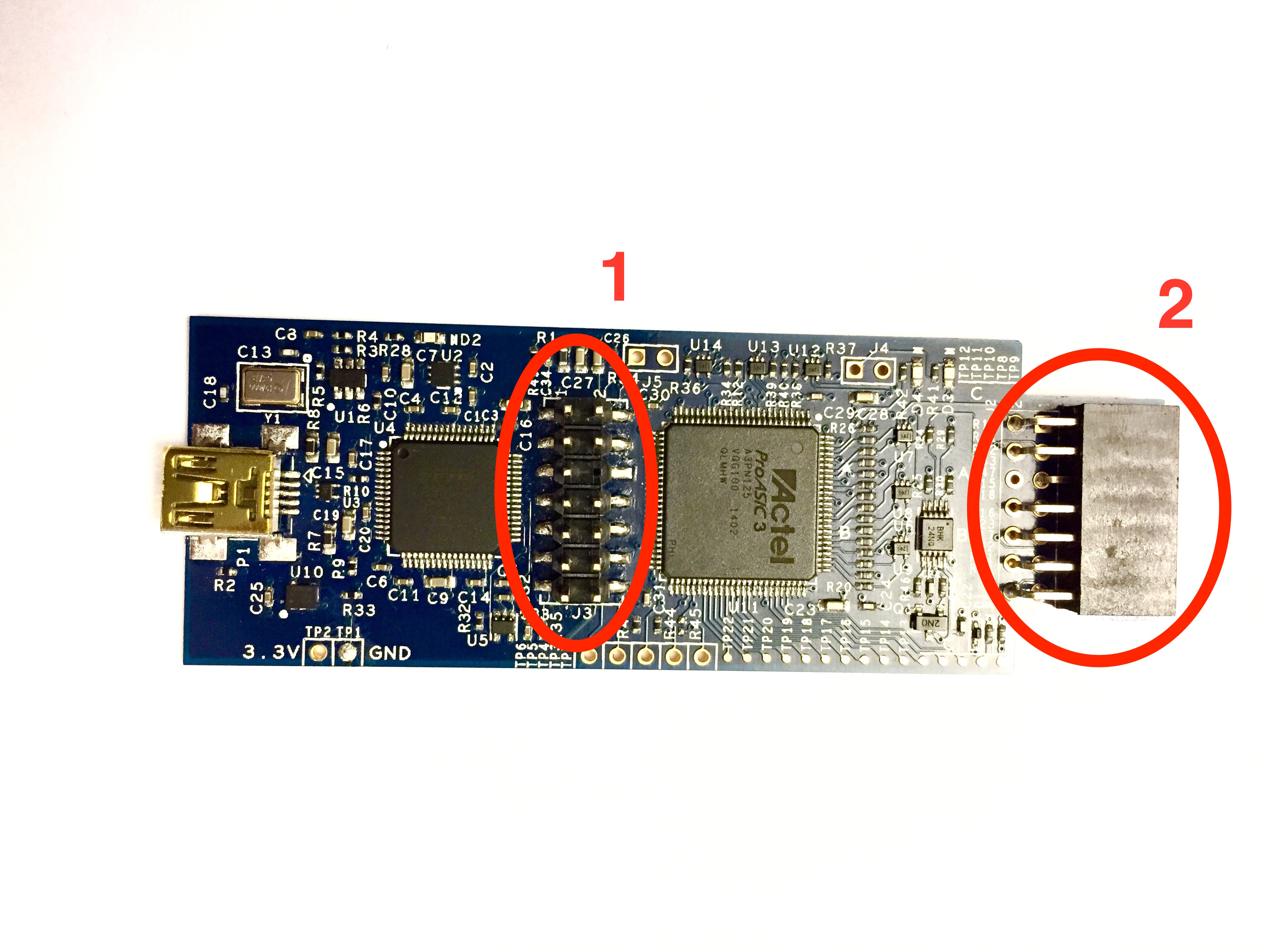
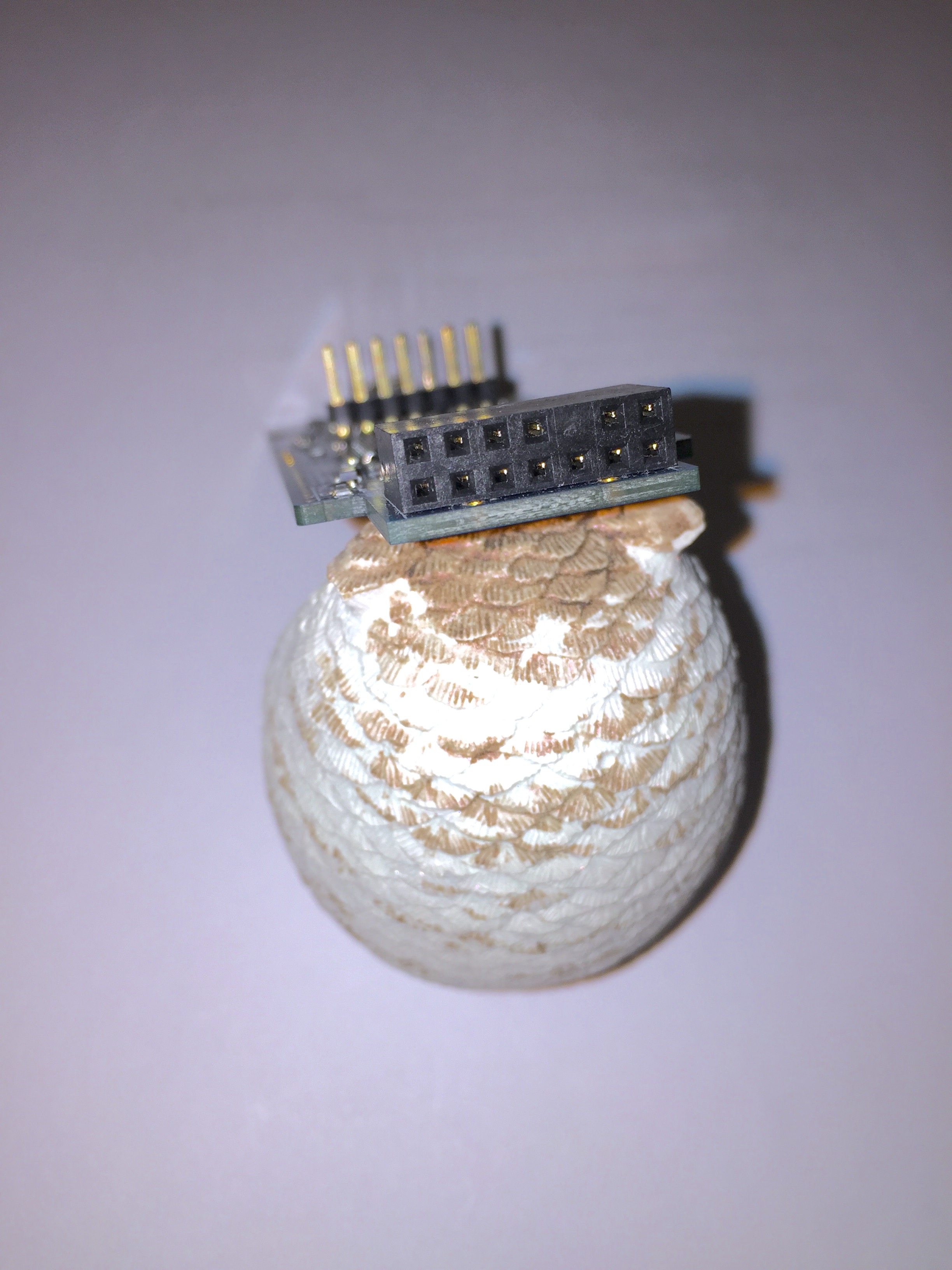
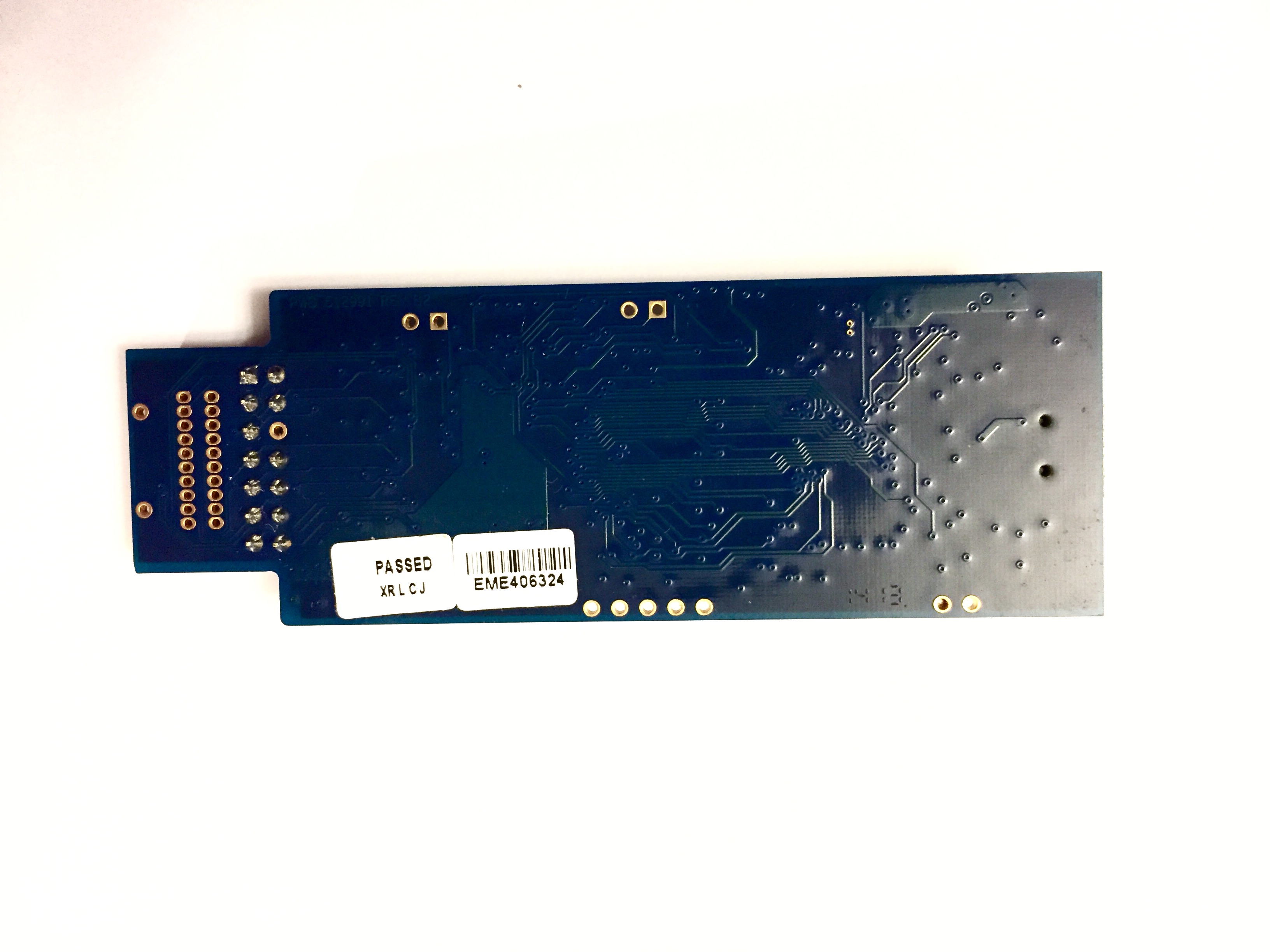
I have XDS100v3 (produced by Embest) debug probe and want to use it for flashing TM4C1294NCPDT parts installed on my own PCB. And at first I want to test flashing and debugging on evaluation board EK-TM4C1294XL. My XDS100v3 hasn't any cable in its kit. So I manually connect pins as described in www.ti.com/.../spma075.pdf document. Then I create the new project in CCS 6.1.3, choose XDS100v3 in Connection menu and click Verify. But a message appears that says "Target not connected, controller detected a break far-away from debug probe".

What's wrong? I connect no external components (such as resistors) as said in SPMA075 that EK-TM4C1294XL has no need in additional elements for debugging via JTAG.

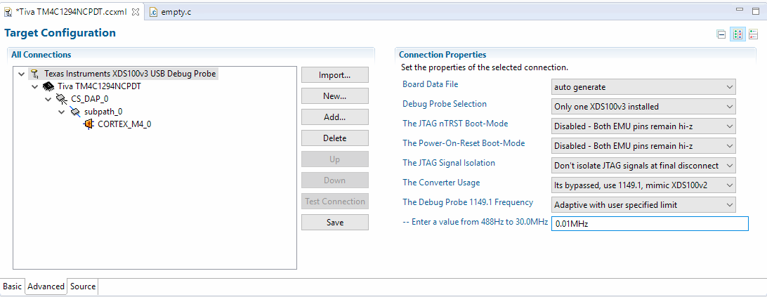
Here is my target *.ccxml:

<?xml version="1.0" encoding="UTF-8" standalone="no"?>
<configurations XML_version="1.2" id="configurations_0">
    <configuration XML_version="1.2" id="configuration_0">
        <instance XML_version="1.2" desc="Texas Instruments XDS100v3 USB Debug Probe" href="connections/TIXDS100v3_Dot7_Connection.xml" id="Texas Instruments XDS100v3 USB Debug Probe" xml="TIXDS100v3_Dot7_Connection.xml" xmlpath="connections"/>
        <connection XML_version="1.2" id="Texas Instruments XDS100v3 USB Debug Probe">
            <instance XML_version="1.2" href="drivers/tixds100v2cs_dap.xml" id="drivers" xml="tixds100v2cs_dap.xml" xmlpath="drivers"/>
            <instance XML_version="1.2" href="drivers/tixds100v2cortexM.xml" id="drivers" xml="tixds100v2cortexM.xml" xmlpath="drivers"/>
            <platform XML_version="1.2" id="platform_0">
                <instance XML_version="1.2" desc="Tiva TM4C1294NCPDT" href="devices/tm4c1294ncpdt.xml" id="Tiva TM4C1294NCPDT" xml="tm4c1294ncpdt.xml" xmlpath="devices"/>
            </platform>
        </connection>
    </configuration>
</configurations>

  • Hello user4299601

    Is the clocking scheme for XDS100v3 in the ccxml file set tot Adaptive clocking?

    Can you please past a snapshot of the ccxml file or better still attach the same to the post.
  • I haven't *.ccxml file yet, because I just trying to verify connection in "New CCS project" menu. Should I finish creating of project and then correct *.ccxml?
  • Hello user4299601

    Yes, you need to have a project ccxml file or a worksapce ccxml file associated with the XDS100v3.
  • OK, I have created simple TI-RTOS project, trying to debug but I got the same error:

    The value is '-183' (0xffffff49).
    The title is 'SC_ERR_CTL_CBL_BREAK_FAR'.
    
    The explanation is:
    The controller has detected a cable break far-from itself.
    The user must connect the cable/pod to the target.

    Also I attached *.ccxml file.

  • Hello user4299601

    The error message means that the VTref pin is not connected correctly from the header to the probe connector

    e2e.ti.com/.../1080750

    Can you check the orientation of pin-1 on the probe connector and pin-1 of the header on the board.?
  • VTRef (TVD) pin is connected to 3.3V of the target board (I tried both variants with and without serial 100 Ohm resistor).
    My full connection is:

    (pin) XDS100v3     target
    (3)   TDI          TDI
    (7)   TDO          TDO
    (1)   TMS          TMS
    (4)   TDIS         GND
    (11)  TCK (TCLKO)  TCK
          GND          GND
    (5)   VTRef (TVD)  3.3V (with and without serial 100 Ohm resistor)

    I check connection on EK-TM4C1294XL by multimeter using signed holes of X1 part. Unused wires are not connected and simply free in the air. Length of the cable is about 7 inches. After your suggestion I tried to set lower clock frequency in advanced properties of the *.ccxml file (even 0.01 Mhz). But it still isn't work.

  • Hello user4299601

    Which type of connector is there on the XDS100v3? The Target board uses a 10 pin ARM pinout.

    Also please send me a snapshot of the ccxml file in Advanced tab where you set the clock frequency.
  • Please find the *.ccxml snapshot in attachment. 

    My piece of XDS100v3 uses only JTAG TI 14-pin scheme (I guessed this because there are KEY on the 6th pin and three GNDs on pins 8, 10 and 12). How I explained before, there were no cable in the kit of XDS probe so I made my own and connected it as describes above. Should I implement scheme from Figure 1 of this wiki and additionally install 22 Ohm resistors? And what about unused pins? Also maybe 7 inches is too much for such cable? Or ICDI interrupts communication with target?

  • Hello user4299601

    Before doing anything else, change the option "The Debug Probe 1149.1 Frequency" from Adaptive to Fixed.
  • Finally, I have got it worked. XDS100v3 has two 14-pin headers and they are not equal. It was necessary to connect to the header on the edge of the board. Unfortunately, all this time I was connecting the target to the header that locating in the middle of the board.
  • Hello user4299601

    The header on the edge of the board is a 10-pin connector. This is mentioned explicitly in the Application Note on the position of the external debug header. If the information in the application note was not clear, then can you explain why it was not, so that we can make appropriate amends to the document.
  • I meant I connected 10-pin header of the EK-TM4C1294XL to the not appropriate header of the XDS100v3 probe. Attached photos show my instance of XDS100v3 and the header #1 is NOT what I needed and #2 is what I need. I found this from the scheme of XDS100v3 that can be downloaded from XDS100 TI-wiki article.

  • Hello user4299601,

    OK, Now I understand it better. May be I need to add XDS100v3 as well to the application document as well.