This thread has been locked.

If you have a related question, please click the "Ask a related question" button in the top right corner. The newly created question will be automatically linked to this question.

TM4C1294 ADC internal +VREFA is Analog comparator VIREF - ACREFCTRL transients can lead to false triggering?

Guru 55913 points
Other Parts Discussed in Thread: INA282, LM4120

EK-TM4C1294NCPDT-XL: +VREFA source has 2.2uf, 0.1uf capacitors before R41 (0R0) into +Vref  and internal ADC +vref.

Added 0.01uf TP13 to ground +VREFA input seemed to reduce frequency of random false triggers.

Inverter transients could be false triggering internal analog comparator but not from -C0n circuit inputs. 

Making R41 say R3k0 may reduce transient magnitude and seemingly change the precision resistor thresholds in ACREFCTL?

Perhaps add ultra fast 14ns Schottky diode TP13 to ground to arrest  any higher magnitude transients?

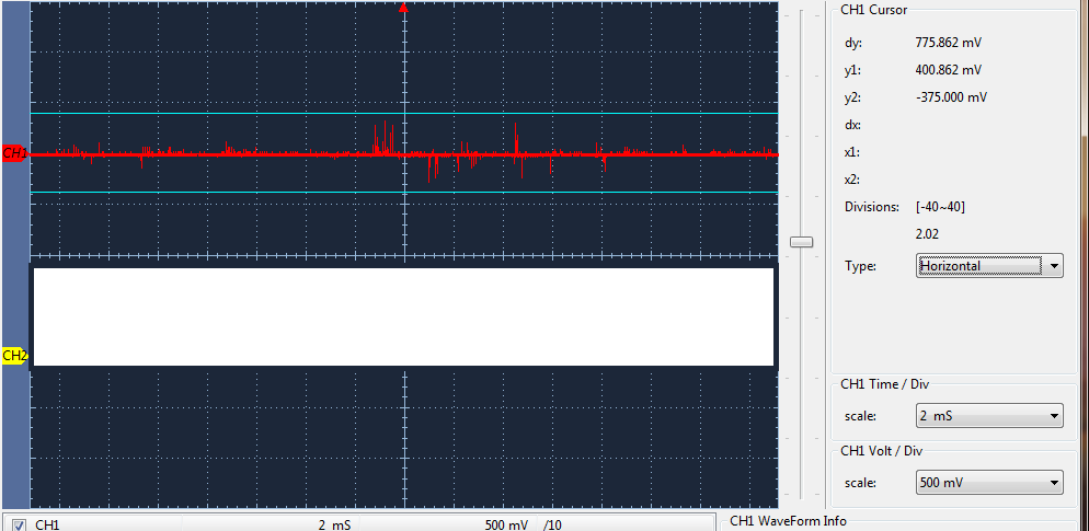
Scope capture  TP13, +VREFA CH2 AC coupling 500mv/cm.

  • Hello BP101

    If you really want to use VREFA+ then I would suggest using a stable voltage reference generator rather than using the VDDA/VDDS supply rail.
  • Hi Amit,

    Have been reviewing TI voltage reference seminar. You have no idea if a series resistor would affect ACREFCTL thresholds? If we can trust the analog comparator ACREFCTL Fig 23-3 , R41 value would seem not to change the resistor ladder values.

    Don't see how an external reference would be any less prone to similar transients unless they are ADC switching capacitor injection pulses. Need to rule out if suspect ACREFCTL false triggers or if the -C0n inputs driven by INA282 current monitors are passing shunt transients. The INA282 has 50Khz switching capacitors SNR is 70db down @10Khz. Low side shunt Isolation to ADC inputs was the reason for selecting INA282 monitor.

    Seems unlikely a current shunt transient yet the PWM module M0nFauts are being tripped randomly at times. If it were shunt related that would be a huge 14.5 amp transient.

  • Hello BP101

    The ADC has a sampling and hold capacitor. There is no switching capacitor on the ADC Vrefa+.
  • Hi Amit,
    Was referring that sample hold capacitor as it switches on and off creates pulses back out the ADC channel. We have a R500 to ground on the channel input to help sink the hold capacitor pulses to ground but even that is no guarantee it will.
  • Hello BP101

    The ADC starts conversion after sample-hold cap is disconnected. I don;t think there is that much of an issue. If however that still a concern of precision, I would suggest something in the INA series for precision ADCs
  • Hi Amit,

    I was not worried of precision rather VDDA is used by ADC reference and analog comparator VDDA via ACREF for VREFI. Noticed ADC0/1 VREP can be changed from VDDA to +VREFA MCU pin and R41=10k sets ADC ref current 330ua. That should effectively isolate analog comparator VDDA derived VREFI from ADC hold capacitor switching current noise being injected back out or onto VDDA from ADC reference.

    Is there any internal electrical difference VREP being set to VDDA versus the +VREFA pin?
  • Hello BP101

    No. That is a switch between source. The stability of the source is what is important. The VDDA/VDDS is more noisy than a stable voltage reference.
  • Hi Amit,

    Figure 15-8 seemed to agree that is the case but......

    With R41=10k, 0.01uf to ground at TP13, VREFP set VREFA+ the samples had much higher values, DC +161v was reading +243v. Switched VREFP back to VDDA, DC reads +161v again. They both use the same +3V3 source from JP2. Not sure how constraining VREFA+ to 330ua is causing the count to go so high compared VREFP=VDDA other than a few 0.1uf caps are now on the other side of R41.

    Any thoughts?
  • Hello BP101

    The placement of the caps could be a possibility on the values being off. But not by such a large value.
  • Morning Amit,

    Scope probe TP13 (VREFA+) and the noise magnitude is much higher over (1v-ptp) with set VREFP=VDDA+. Seems R41 now acts like a low pass filter of VDD/ADDA 10k, 0.01uf to ground? Oddly no more random PANICS have occurred after R41=10k, hate when this happens makes it hard to know what to do. Did notice the TM4CXL-LP schematic VDD tied to VDDA+. Our custom PCB layout has VDDA+ tied VREF+ into R10K to a 5m ferrite bead at +3v3 (untested). Though now aware may have to tweak all SW sample filter values at some point.

    Considering LM4120 precision reference adding pads custom PCB for testing as well, fail safe gremlins may return. Do notice there is no ferrite +3v3 at VDD input but think could be prudent in this case but maybe 0R0 versus R10k.
  • Hello BP101

    1V ptp would cause a device reset if this is happening on VDDA.