This thread has been locked.

If you have a related question, please click the "Ask a related question" button in the top right corner. The newly created question will be automatically linked to this question.

EPI won't write if D15 set


Using Tiva '129 (TM4C129XNCZAD) CPU

CCS v6.1.3.00033

I have a situation I can read and write values using the EPI, but if I attempt to write a word with D15 set to one, the write cycle does not occur.

It's not that all the control/address/data lines are all correct except one signal is weird causing failure, there is no motion whatsoever on any line.

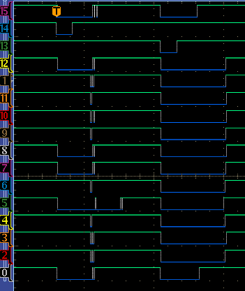
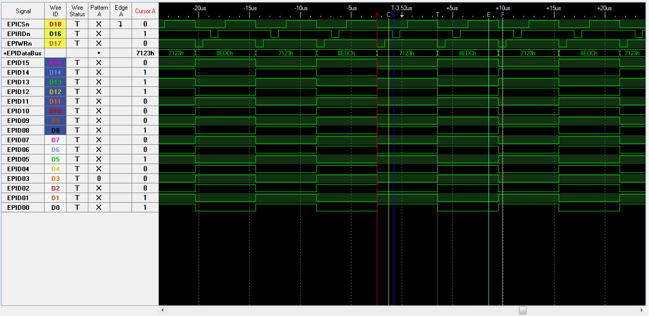
I have a logic analyzer hooked to the control/address/data lines and have set up a situation where a read is followed immediately by a write.

I trigger on the read.

When the write following the read has D15 being zero, all is good.  If D15 is a one, there is no motion on any control/address/data lines.

Here are the configuration commands I am using for the EPI:

  EPIDividerSet(EPI0_BASE, 4);
  EPIModeSet(EPI0_BASE, EPI_MODE_HB16);
  EPIConfigHB16Set(EPI0_BASE, EPI_HB16_MODE_SRAM | EPI_HB16_CSCFG_CS | EPI_HB16_WRWAIT_0 | EPI_HB16_RDWAIT_0, 0);
  EPIAddressMapSet(EPI0_BASE, EPI_ADDR_RAM_BASE_6 | EPI_ADDR_RAM_SIZE_256B );

I am reading and writing to the same address: 0x600000EE

I am at a loss at how changing data could affect whether an operation takes place.

  • Hello Greg,

    Can you please provide the Logic Analyzer snapshot of when it is working and when it is not working for comparison? In the meantime I will try to reconstruct the test code.
  • Hello Greg,

    Also can you please let me know the following data as well

    1. Device Revision: A0, A1 or A2? Whether it is a DK-TM4C129x or a Custom Board.
    2. System Clock being used?
  • Device rev A2

    Custom board.

    System clock: 25MHz oscillator on main input

    The shot below is when it works.

    The top three lines are:

    1. An address line being used as a chip select.  It is hooked to EPI0S19
    2. RDn (EPI0S28)
    3. WRn (EPI0S29)

    EPI0S30 is being used as a chip enable elsewhere on the board but is not shown here.  Basically, there is a 74245 whose enable line is hooked to EPI0S30
    , so the address line will be a chip select as long as EPI0S30 is asserted.

    All the other lines are data lines with the bottom one '0' hooked to D15 EPI0S15

    The value for the write is all zeros.

    Here's the same program with the only change being that we are now writing a 0x8000 to the address:

  • In case you really want to see EPI0S30, here it is attached to a real scope probe at the bottom of the picture:

  • Hello greg,

    I ran the following program and I do not see any issue with either Read or Write when the EPI Data 15 bit is set. The only difference is that I have clocking set up for 16MHz internal oscillator but that does not have any impact on the EPI behavior.

    #include <stdbool.h>
    #include <stdint.h>
    #include "inc/hw_ints.h"
    #include "inc/hw_memmap.h"
    #include "inc/hw_types.h"
    #include "inc/hw_gpio.h"
    #include "driverlib/gpio.h"
    #include "driverlib/interrupt.h"
    #include "driverlib/pin_map.h"
    #include "driverlib/sysctl.h"
    #include "driverlib/epi.h"
    
    //*****************************************************************************
    //
    // Use the following to specify the GPIO pins used by the SDRAM EPI bus.
    //
    //*****************************************************************************
    #define EPI_PORTA_PINS (GPIO_PIN_7 | GPIO_PIN_6)
    #define EPI_PORTB_PINS (GPIO_PIN_3)
    #define EPI_PORTC_PINS (GPIO_PIN_7 | GPIO_PIN_6 | GPIO_PIN_5 | GPIO_PIN_4)
    #define EPI_PORTG_PINS (GPIO_PIN_1 | GPIO_PIN_0)
    #define EPI_PORTH_PINS (GPIO_PIN_3 | GPIO_PIN_2 | GPIO_PIN_1 | GPIO_PIN_0)
    #define EPI_PORTK_PINS (GPIO_PIN_5)
    #define EPI_PORTL_PINS (GPIO_PIN_3 | GPIO_PIN_2 | GPIO_PIN_1 | GPIO_PIN_0)
    #define EPI_PORTM_PINS (GPIO_PIN_3 | GPIO_PIN_2 | GPIO_PIN_1 | GPIO_PIN_0)
    #define EPI_PORTP_PINS (GPIO_PIN_3 | GPIO_PIN_2)
    
    int main(void)
    {
    
    	uint32_t ui32Data;
    	SysCtlPeripheralEnable(SYSCTL_PERIPH_EPI0);
    
      //
      // For this example EPI0 is used with multiple pins on PortA, B, C, G, H,
      // K, L, M and N.  The actual port and pins used may be different on your
      // part, consult the data sheet for more information.
      // TODO: Update based upon the EPI pin assignment on your target part.
      //
      SysCtlPeripheralEnable(SYSCTL_PERIPH_GPIOA);
      SysCtlPeripheralEnable(SYSCTL_PERIPH_GPIOB);
      SysCtlPeripheralEnable(SYSCTL_PERIPH_GPIOC);
      SysCtlPeripheralEnable(SYSCTL_PERIPH_GPIOG);
      SysCtlPeripheralEnable(SYSCTL_PERIPH_GPIOH);
      SysCtlPeripheralEnable(SYSCTL_PERIPH_GPIOK);
      SysCtlPeripheralEnable(SYSCTL_PERIPH_GPIOL);
      SysCtlPeripheralEnable(SYSCTL_PERIPH_GPIOM);
      SysCtlPeripheralEnable(SYSCTL_PERIPH_GPIOP);
    
      //
      // This step configures the internal pin muxes to set the EPI pins for use
      // with EPI.  Please refer to the datasheet for more information about pin
      // muxing.  Note that EPI0S27:20 are not used for the EPI SDRAM
      // implementation.
      //
      GPIOPinConfigure(GPIO_PH0_EPI0S0);
      GPIOPinConfigure(GPIO_PH1_EPI0S1);
      GPIOPinConfigure(GPIO_PH2_EPI0S2);
      GPIOPinConfigure(GPIO_PH3_EPI0S3);
      GPIOPinConfigure(GPIO_PC7_EPI0S4);
      GPIOPinConfigure(GPIO_PC6_EPI0S5);
      GPIOPinConfigure(GPIO_PC5_EPI0S6);
      GPIOPinConfigure(GPIO_PC4_EPI0S7);
      GPIOPinConfigure(GPIO_PA6_EPI0S8);
      GPIOPinConfigure(GPIO_PA7_EPI0S9);
      GPIOPinConfigure(GPIO_PG1_EPI0S10);
      GPIOPinConfigure(GPIO_PG0_EPI0S11);
      GPIOPinConfigure(GPIO_PM3_EPI0S12);
      GPIOPinConfigure(GPIO_PM2_EPI0S13);
      GPIOPinConfigure(GPIO_PM1_EPI0S14);
      GPIOPinConfigure(GPIO_PM0_EPI0S15);
      GPIOPinConfigure(GPIO_PL0_EPI0S16);
      GPIOPinConfigure(GPIO_PL1_EPI0S17);
      GPIOPinConfigure(GPIO_PL2_EPI0S18);
      GPIOPinConfigure(GPIO_PL3_EPI0S19);
      GPIOPinConfigure(GPIO_PB3_EPI0S28);
      GPIOPinConfigure(GPIO_PP2_EPI0S29);
      GPIOPinConfigure(GPIO_PP3_EPI0S30);
      GPIOPinConfigure(GPIO_PK5_EPI0S31);
    
      //
      // Configure the GPIO pins for EPI mode.  All the EPI pins require 8mA
      // drive strength in push-pull operation.  This step also gives control of
      // pins to the EPI module.
      //
      GPIOPinTypeEPI(GPIO_PORTA_BASE, EPI_PORTA_PINS);
      GPIOPinTypeEPI(GPIO_PORTB_BASE, EPI_PORTB_PINS);
      GPIOPinTypeEPI(GPIO_PORTC_BASE, EPI_PORTC_PINS);
      GPIOPinTypeEPI(GPIO_PORTG_BASE, EPI_PORTG_PINS);
      GPIOPinTypeEPI(GPIO_PORTH_BASE, EPI_PORTH_PINS);
      GPIOPinTypeEPI(GPIO_PORTK_BASE, EPI_PORTK_PINS);
      GPIOPinTypeEPI(GPIO_PORTL_BASE, EPI_PORTL_PINS);
      GPIOPinTypeEPI(GPIO_PORTM_BASE, EPI_PORTM_PINS);
      GPIOPinTypeEPI(GPIO_PORTP_BASE, EPI_PORTP_PINS);
    
      EPIDividerSet(EPI0_BASE, 4);
      EPIModeSet(EPI0_BASE, EPI_MODE_HB16);
      EPIConfigHB16Set(EPI0_BASE, EPI_HB16_MODE_SRAM | EPI_HB16_CSCFG_CS | EPI_HB16_WRWAIT_0 | EPI_HB16_RDWAIT_0, 0);
      EPIAddressMapSet(EPI0_BASE, EPI_ADDR_RAM_BASE_6 | EPI_ADDR_RAM_SIZE_256B );
    
      while(1)
      {
    	  ui32Data = HWREGH(0x600000EE);
    	  SysCtlDelay(10);
    	  HWREGH(0x600000EE) = 0x7123;
    	  SysCtlDelay(10);
    	  ui32Data = HWREGH(0x600000EE);
    	  SysCtlDelay(10);
    	  HWREGH(0x600000EE) = 0x8EDC;
    	  SysCtlDelay(10);
      }
    }
    

    The only other thing I could think of are

    1. Is the debug being done on the EPI pins or on some logic output based on EPI pins.

  • The logic analyzer shown is actually pretty far away: a couple transceivers and a 40 pin ribbon cable on another board.

    The reason being that the other board is mid 1990's tech with nice .1" center pins that you can attach probes to.

    The board with the Tiva is all teeny tiny surface mount that is hard to probe.

    So I bit the bullet and looked at the EPICSn line coming out of the CPU and it looks like this:

    Obviously some contention going on. 

    Let's just call finding this contention the answer shall we?

    Thanks for all the help!