This thread has been locked.

If you have a related question, please click the "Ask a related question" button in the top right corner. The newly created question will be automatically linked to this question.

TM4C129ENCPDT UART0 Interrupt

Other Parts Discussed in Thread: EK-TM4C129EXL

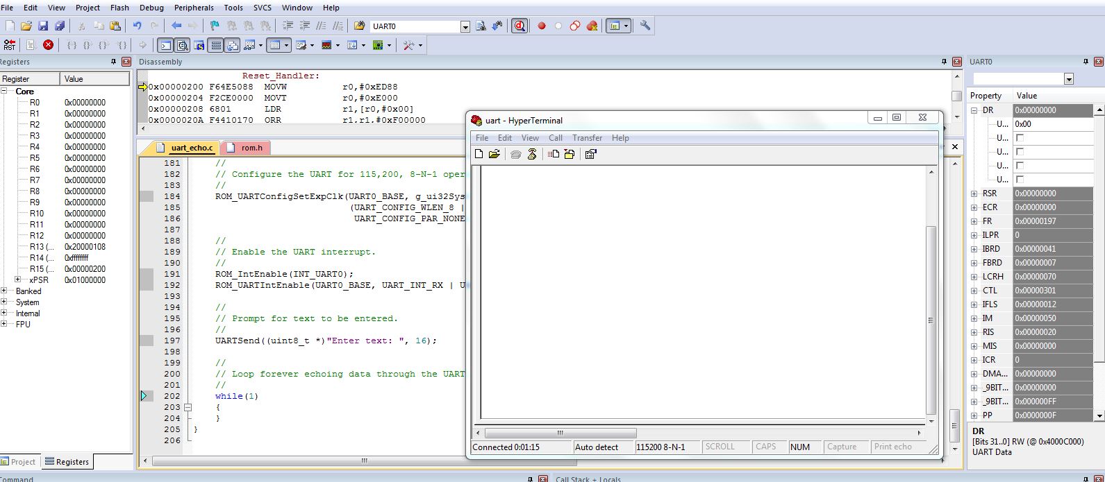
I am just a beginner to TM4C129 uC. I am facing a problem that the Interrupt is not getting triggered while trying do the UART0 interface using the example code provided. Could some help me to troubleshoot the mistake?. The launch pad used is EK-TM4C129EXL. Thanks in advance.  

#include <stdint.h>
#include <stdbool.h>
#include "inc/hw_ints.h"
#include "inc/hw_memmap.h"
#include "driverlib/debug.h"
#include "driverlib/gpio.h"
#include "driverlib/interrupt.h"
#include "driverlib/pin_map.h"
#include "driverlib/rom.h"
#include "driverlib/rom_map.h"
#include "driverlib/sysctl.h"
#include "driverlib/uart.h"

//*****************************************************************************
//
//! \addtogroup example_list
//! <h1>UART Echo (uart_echo)</h1>
//!
//! This example application utilizes the UART to echo text. The first UART
//! (connected to the USB debug virtual serial port on the evaluation board)
//! will be configured in 115,200 baud, 8-n-1 mode. All characters received on
//! the UART are transmitted back to the UART.
//
//*****************************************************************************

//****************************************************************************
//
// System clock rate in Hz.
//
//****************************************************************************
uint32_t g_ui32SysClock;

//*****************************************************************************
//
// The error routine that is called if the driver library encounters an error.
//
//*****************************************************************************
#ifdef DEBUG
void
__error__(char *pcFilename, uint32_t ui32Line)
{
}
#endif

//*****************************************************************************
//
// The UART interrupt handler.
//
//*****************************************************************************
void
UARTIntHandler(void)
{
uint32_t ui32Status;

//
// Get the interrrupt status.
//
ui32Status = ROM_UARTIntStatus(UART0_BASE, true);

//
// Clear the asserted interrupts.
//
ROM_UARTIntClear(UART0_BASE, ui32Status);

//
// Loop while there are characters in the receive FIFO.
//
while(ROM_UARTCharsAvail(UART0_BASE))
{
//
// Read the next character from the UART and write it back to the UART.
//
ROM_UARTCharPutNonBlocking(UART0_BASE,
ROM_UARTCharGetNonBlocking(UART0_BASE));

//
// Blink the LED to show a character transfer is occuring.
//
GPIOPinWrite(GPIO_PORTN_BASE, GPIO_PIN_0, GPIO_PIN_0);
GPIOPinWrite(GPIO_PORTN_BASE, GPIO_PIN_0, 1);

//
// Delay for 1 millisecond. Each SysCtlDelay is about 3 clocks.
//
SysCtlDelay(g_ui32SysClock / (1000 * 3));

//
// Turn off the LED
//
GPIOPinWrite(GPIO_PORTN_BASE, GPIO_PIN_0, 0);
}
}

//*****************************************************************************
//
// Send a string to the UART.
//
//*****************************************************************************
void
UARTSend(const uint8_t *pui8Buffer, uint32_t ui32Count)
{
//
// Loop while there are more characters to send.
//
while(ui32Count--)
{
//
// Write the next character to the UART.
//
ROM_UARTCharPutNonBlocking(UART0_BASE, *pui8Buffer++);

}
}

//*****************************************************************************
//
// This example demonstrates how to send a string of data to the UART.
//
//*****************************************************************************
int
main(void)
{
//
// Set the clocking to run directly from the crystal at 120MHz.
//
g_ui32SysClock = MAP_SysCtlClockFreqSet((SYSCTL_XTAL_25MHZ |
SYSCTL_OSC_MAIN |
SYSCTL_USE_PLL |
SYSCTL_CFG_VCO_480), 120000000);
//
// Enable the GPIO port that is used for the on-board LED.
//
ROM_SysCtlPeripheralEnable(SYSCTL_PERIPH_GPION);

//
// Enable the GPIO pins for the LED (PN0).
//
ROM_GPIOPinTypeGPIOOutput(GPIO_PORTN_BASE, GPIO_PIN_0);

//
// Enable the peripherals used by this example.
//
ROM_SysCtlPeripheralEnable(SYSCTL_PERIPH_UART0);
ROM_SysCtlPeripheralEnable(SYSCTL_PERIPH_GPIOA);

//
// Enable processor interrupts.
//
ROM_IntMasterEnable();

//
// Set GPIO A0 and A1 as UART pins.
//
GPIOPinConfigure(GPIO_PA0_U0RX);
GPIOPinConfigure(GPIO_PA1_U0TX);
ROM_GPIOPinTypeUART(GPIO_PORTA_BASE, GPIO_PIN_0 | GPIO_PIN_1);

//
// Configure the UART for 115,200, 8-N-1 operation.
//
ROM_UARTConfigSetExpClk(UART0_BASE, g_ui32SysClock, 115200,
(UART_CONFIG_WLEN_8 | UART_CONFIG_STOP_ONE |
UART_CONFIG_PAR_NONE));

//
// Enable the UART interrupt.
//

ROM_IntEnable(INT_UART0);
ROM_UARTIntEnable(UART0_BASE, UART_INT_RX | UART_INT_RT);


//
// Prompt for text to be entered.
//

UARTSend((uint8_t *)"\033[2JEnter text: ", 16);

//
// Loop forever echoing data through the UART.
//
while(1)
{

}
}

  • Hello Kruian,

    1. Have you mapped the interrupt handler in the startup_ccs.c file in the interrupt table
    2. The interrupt handler is invoked when a character is sent from the console terminal. Do you have a console program like TeraTerm or PuTTy working? A simple way to check the same is that with the console program running and the code execution, you should see the message "Enter text: " on the console.
  • Thanks Amit,

    1) I am using Keil uV5.20 IDE, I have included the given startup file "startup_rvmdk.s", and there the interrupt  is mapped as follows "ROM_UARTCharPutNonBlocking" >> "ROM_UARTTABLE[15]" >>  UARTIntHandler()

    2) I have tried the same using Hyper Terminal console while the same code in execution. But it is not displaying any data in console terminal as well as the "System viewer" >> "UART0" >> "UART_DR". The value in UART_DR_DATA is 0x00 always. Please find the screen short of the same. Hope someone have a solution for this.

    Thank you very much.

  • Kurian,

    Can you try to add other "debug aids" to your code? Some suggestions:

    - Configure another led to blink regularly, so that you can see that the board is running. You can do something as simple (and ugly) as LEDON/DELAY/LEDOFF/DELAY loop, so that you are certain that the program is running.
    - Code does not seem wrong, and all the pins appear to be properly mapped and peripherals enabled. Did you triple check your UART port on the PC, are you sure it works? Maybe upload an example firmware to your board which you are SURE that sends data via the serial port... I suspect the PC, as you are not even receiving the initial message.
    - Try to periodically send something via the UART (just as you blink the led periodically, loop a character out the port).
    - Do you have a scope or digital analyzer that allows you to see the electric signals?

    These are basic debug concepts that are likely to help you for many years to come... Make use of them.

    Bruno
  • Hello Kurian

    Does any of the launchpad examples work with UART0?

    Also please ensure that the header pins for UART on the launchpad are in the horizontal orientation indicated for UART.
  • Hi Bruno and Amit,

    Thank you for your guidance

    • The blinky example code is working fine >> board is fine.
    • I have included LEDs and checked the electrical signal using DSO. The signals are not available at pins.
    • So far on troubleshooting. I have observed that after "ROM_UARTConfigSetExpClk()" baud rate configuration the UART_DR register (Value: 0x00000500) is giving break error and framing error
    • On sending data iterative through the while loop at the end of the code, electric signals are available at Tx pin. The data register value of other UART0 examples are 0x00 too.
    • Header pins for UART on the launchpad are in right orientation.

    Any help is appreciated

    Thanks and Regards,

    Kurian Thomas

  • MAP_SysCtlPeripheralEnable(SYSCTL_PERIPH_GPIOA);
    ROM_SysCtlPeripheralEnable(SYSCTL_PERIPH_UART0);
    MAP_GPIOPinConfigure(GPIO_PA0_U0RX);
    MAP_GPIOPinConfigure(GPIO_PA1_U0TX);
    MAP_GPIOPinTypeUART(GPIO_PORTA_BASE, GPIO_PIN_0 | GPIO_PIN_1);
    
    ROM_UARTConfigSetExpClk(UART0_BASE, g_ui32SysClock, 115200,
    (UART_CONFIG_WLEN_8 | UART_CONFIG_STOP_ONE | UART_CONFIG_PAR_NONE));
    
    while(1)
    {
       ROM_UARTCharPutNonBlocking(UART0_BASE,'A');
       SysCtlDelay(1000000);
       // Hint: add a led on/wait/led off here
    }


    Kurian,

    The blink example working shows that the board is fine, but my suggestion was to incorporate a blinking led into your UART project, so that you are sure that the program is running while you are "looking for electric signals" with your scope. Can you do that?

    Next, try a very basic uart send program without interrupts, and see if you get uart signal coming out the proper pin. Something like what I pasted up here.

    Let us know.

  • Hello Kurian,

    I did mention to run an example which uses UART0, as we need to test if the UART is working correctly. A break and framing error indicates a mismatch on the baud rate. Did you check the windows manager setting for the COM port in question.
  • Why dont u use UARTIntRegister ? Can you try to use this function and delete your extern from startup ..

  • Hello Tiva_tcik53

    If you use UARTIntRegister then the entire interrupt table is remapped to SRAM. This causes 1K bytes of SRAM to be held up for interrupt vector table rather than using Flash which is more plentiful resource.
  • Dear Team,

    Thank you very much.

    I have tried UART0, UART1, UART2, UART3, UART4, UART5 with "UARTLoopbackEnable()" and there after removed the loopback function & mapped the signals to UART pins , its working fine. 

    Regards,

    Kurian Thomas