This thread has been locked.

If you have a related question, please click the "Ask a related question" button in the top right corner. The newly created question will be automatically linked to this question.

TM4C123GXL H-Bridge Motor Direction Control

Other Parts Discussed in Thread: ENERGIA, LMD18200, TM4C123GH6PM

I am using a TM4C123GXL and H-Bridge for DC motor control.  I managed to generate a PWM signal and control the speed of the motor, but only in 1 direction.  I cannot get to reverse the direction of the motor.  The H-Bridge logic inputs need to be inverted to reverse the direction.  However, I cannot seem to do that with code.  On Arduino, people have been using digitalWrite(  (Pin Number), LOW) and digitalWrite(   (Pin Number),  HIGH) and have worked for them.  Is there any way to do that but in a Code Composer Studio project?  I am not trying to use Energia.

I know for high, GPIOPinWrite() works but I can't seem to get the low part.

Any help would be greatly appreciated!!!

  • Hello Hak

    GPIOPinWrite has 3 arguments. The first is the GPIO Base address, the next is the pin number and the last is the value. So if you write the 3rd argument as the Pin Number define, the Pin will be high. If you write the value of 0 then the Pin would be low.

    Now the very important topic of motor control. Not a good idea to use GPIO control for motor control, when PWM is already available. Now you mention logic inputs need to be inverted to reverse the direction. The PWM is already a signal going High and Low and High.... Are you sure you mean invert or reverse PWM control sequence. I would ask you to go through the following video....

    www.youtube.com/watch
  • Hi Hak,
    I too am using a TM4C123... and H-Bridge for DC motor control ( two motors).
    My previous development experience never benefited from built in software or an OS so I tend to like to manipulate registers directly (as you'll see below).
    I didn't know there was an RTOS PWM system available so wrote my own.
    I defined a struct containing various state variables, pointers to PWM and QEI registers, etc. and made two instantiations LeftMotor and RightMotor. The control routine runs in the background, called by a clock generated interrupt. I simply pass a reference to the control routine (PID control) like this...

    // This is the motor control clock Interrupt Service Routine
    // The clock times out every 4 milliseconds so this routine runs 250 times per second
    void clockPID(void){
    PID_Control(&Right_Motor);
    PID_Control(&Left_Motor);
    }

    Here's my code to control direction in routine PID_Control(motor)...

    if(motor->DesiredVelocity > 0)
    *motor->DirPort |= motor->DirPin; // Forward
    else
    *motor->DirPort &= ~motor->DirPin; // Reverse

    As you see, the control routine uses the desired velocity to set the corresponding direction control pin as appropriate.

    Here's the motor struct...

    struct motor{
    char ID;
    volatile int DriveMode;
    volatile int dState;
    volatile int iState;
    volatile int LastDif;
    volatile int Power;
    volatile int DesiredVelocity;
    volatile uint *PWM_PulseWidth;
    volatile uint32_t *DirPort;
    uint DirPin;

    volatile uint BrakePosition;
    volatile uint CurrentPosition;

    // Quadrature Registers
    volatile uint32_t* QEI_Control;
    volatile uint32_t* QEI_Status;
    volatile uint32_t* QEI_Position;
    volatile uint32_t* QEI_MaxPosition;
    volatile uint32_t* QEI_TimerLoad;
    volatile uint32_t* QEI_Timer;
    volatile uint32_t* QEI_VelocityCounter;
    volatile uint32_t* QEI_Velocity;
    volatile uint32_t* QEI_InterruptEnable;
    volatile uint32_t* QEI_RawInterruptStatus;
    volatile uint32_t* QEI_InterruptClear;
    };

    Here's the structure initialization for the left motor...

    void InitLeftMotor(void){

    L_Motor.ID = 'L';

    L_Motor.Power = 0;
    L_Motor.DesiredVelocity = 0;
    L_Motor.dState = 0;
    L_Motor.iState = 0;

    L_Motor.DriveMode = BRAKE;

    L_Motor.QEI_Control = &QEI1_CTL_R;
    L_Motor.QEI_Status = &QEI1_CTL_R+1;
    L_Motor.QEI_Position = &QEI1_CTL_R+2;
    L_Motor.QEI_Velocity = &QEI1_CTL_R+7;
    L_Motor.QEI_InterruptEnable = &QEI1_CTL_R+8;
    L_Motor.QEI_RawInterruptStatus = &QEI1_CTL_R+9;
    L_Motor.QEI_InterruptClear = &QEI1_CTL_R+10;

    L_Motor.PWM_PulseWidth = &PWM1_3_CMPB_R;
    L_Motor.DirPort = &GPIO_PORTB_DATA_R;
    L_Motor.DirPin = 0x00000008;

    *L_Motor.QEI_Position = (uint32_t)0x7fffffff;
    L_Motor.BrakePosition = (uint32_t)0x7fffffff;
    }

    It's just one approach. Hope this helps.
    If anyone else reads this your constructive criticism would be most welcome.
    Cheers,
    Dave
  • Thank you - your efforts to assist are appreciated.   Both w/in the original post - and now yours - mention is made of an, "H-Bridge."    (Singular - just one!)   It's firm's/my belief that TWO such "H-Bridges" are required to produce Software controlled, Bi-Directional, Brushed DC Motor Control.   (i.e. "each" motor lead is routed to a separate H-Bridge)    Language IS important - an "H-Bridge" defines two FETs - wired so that a common output may switch between Supply (+) & Supply (-).   By itself (singular) such an H-Bridge is unable to change motor direction.

    Thanks to poster/friend Robert - I must announce my "unique" (yet WRONG) sense of "H Bridge" to have meant "Half-Bridge" which is a MINORITY Usage - if used at all...   Firm/I have spent past 2 months designing evaluation boards for Power FETs - which contain gate driver and just TWO Power FETs.  And I swear (or I dreamed) that FET vendor called that board "H-Bridge!"   I agree that more conventional usage recognizes four FETs - with EACH FET making up one of the vertical members w/in the "H."    And indeed - that 4 FET implementation CAN cause Bi-Directional Control - via SW - of an (antiquated) Brushed Motor.   And - what got me in trouble - is the recognition that THREE Half-Bridges (also H-Bridge, (maybe)) can Bi-Directionally Control a superior/modern BLDC Motor!

    I allow the following para. to remain - as penance - I had locked in to TWO FETs (as we have employed) to "borrow" H-Bridge - which is just WRONG!   Mea Culpa!

    When (and if) only a Single H-Bridge is employed - the Brushed motor ties one (of its two) leads to the H-Bridge - the other to either, "Positive or Negative Motor Supply."   In this topology - the motor can only rotate in one direction - to change direction requires halting the motor - and reversing the "fixed" supply connection to the "non-H-Bridge connected" motor lead.

    Again - with TWO H-Bridges deployed (NOT the single one - mentioned here twice) it is possible for software to control (both) motor speed and direction.

    As to David's post - he appears to be writing to an, "Integrated Motor Controller" which exceeds the capabilities of a, Single H-Bridge.   (may in fact embody TWO (or possibly more) H-Bridges w/in its integrated package.   The "tip-off" here is David's defining a, "Motor DirPort" - which (usually) is a single "Direction Control" pin on the more complex "Integrated Motor Controller."

    Our initial poster - if indeed his (proper, required, Power Stage) IS PRESENT and includes dual H-Bridge(S) - may achieve "Reverse" (in one simple implementation) by ordering one H-Bridge to emit "Output HIGH" (w/out PWM) and by then applying PWM to the second H-Bridge.   Reversing that procedure will enable directional control - but should not be done unless the motor is running at low speeds - or is stopped.

    A single H-Bridge (even one implemented in Gold) - was, is, and remains INCAPABLE of employing software to Reverse the Direction of a, "Controlled Brushed Motor" - which has one lead (necessarily) tied to the Motor Supply.

  • cb1, in my experience (and every reference I've seen) an H bridge has 4 power devices, a single pair forms a 1/2H with three of those capable of controlling an induction or BLDC motor. I am sure you know this but have momentarily slipped a mental cog.

    You do use a separate output to control direction if you only use a single PWM but as you note two PWMs may simplify the logic. There may be other benefits as well but those are beyond this discussion.

    Robert

    Draw out a PM motor power circuit with motor in circuit. The H is visually apparent.
  • Whoops - may I retreat to a, "Half H-Bridge, then?"   Hey - "H-Bridge may stand for Half-Bridge - may it not?"   (maybe? - one hopes so...)

    In firm's/my evaluation of a variety of Power FETs - we found it best to create a small pcb holding TWO FETs - and an adjacent GateDriver - and Three such pcbs were (then) able to fully/properly drive 1.5KW BLDC motors.

    I believe that even the FET maker called our TWO FET design an, "H-Bridge." (although maybe "Half-Bridge" was meant.)

    Robert - thank you - surely I'll hear from my "fans" - I'd take this opportunity to award myself a "Verify" (like another) - if only I could...
    (now where did I leave my pistol?...)

    Driving and/or Writing, "Under the Influence" - may not - at all times - make great sense...

    [edit/addition]   I've let my error remain - yet provided "explanation" (even though taught in L School to, "Never Explain or Complain.")   Note that I (neither) inferred nor asserted such fact... (nor Self-Verified...)

  • Insofaras "A picture is worth a thousand words", how can I post a picture?
  • Hello David

    In the reply pane, use the "Use rich formatting" link at the bottom right.
  • Click upon, "Use rich formatting" (found beneath the post area, left side (when you're responding).

    The 10th icon (from the left), bottom row, marked (when moused over) "Insert/Edit Media" enables you to "pull" from your PC.

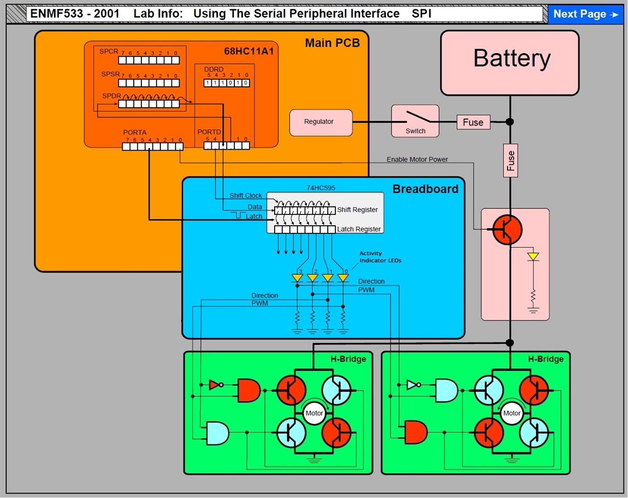
  • A sketch from 15 years ago to illustrate elements of automation to mechanical students...

  • Nice drawing - that HC11 may (even) exceed that 15 year marking. And those are bi-polar transistors - replaced by far more efficient FETs.

    Not shown are the (necessary) Gate Drivers - required when Motor Voltage exceeds the acceptable voltage (and current) capabilities of the logic devices w/in your drawing.

    We should note that today there are "Integrated Devices" which include "all four" FETs (i.e. "H-Bridge") - speeding, easing & enhancing "Brushed Motor Control."
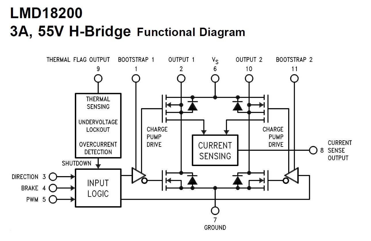
  • HoHo. Yes indeed. The actual H-bridges were the venerable LMD18200 which simplified design considerably.

    After years of working with 6502s and 6809s I was absolutely delighted to discover the 68HC11.

    Now I'm even more delighted to discover the TM4C123GH6PM launchpad with TIs terrific support, the Peripheral Driver Library and RTOS, I mean wow, just wow.

  • There is another approach using a single PWM. One 1/2H is fed with the inverse signal of the other. The net effect is that at 0% the motor is full speed in one direction, at 100% it's full speed in the other direction and at 50% it is at zero speed. There are some advantages to this, particularly around zero speed.

    Robert
  • That's interesting - I recall reading of that technique - but have never implemented nor tried myself.

    We note that a (possible) weakness is the "Halfing" of PWM resolution.   For instance - increasing the duty cycle of One Side by 5% - yields a 10% change at the Motor!   And - if it is key/critical to remain at, "Halt" - some position monitoring (beyond speed monitoring) will be required.   Software must then regularly monitor the position sensor - and "tweak" PWM to maintain the "Halt."   No such effort nor position monitor is required when, "independent command" of each 1/2H is employed.   In addition - current is always flowing - even when - and especially when - the motor is halted.   (no motor current flows - when halted - via the more common command method.)

    As to "advantages" - the motor is likely to start faster and exacting position control (when a (serious) position sensor is employed) is enjoyed.   The number of required GPIOs is cut in half - I can't readily identify further advantages...

  • cb1 said:
    For instance - increasing the duty cycle of One Side by 5% - yields a 10% change at the Motor! 

    Yep, although I'm not sure it's practically significant even with an 8 bit PWM.

    cb1 said:
    And - if it is key/critical to remain at, "Halt" - some position monitoring (beyond speed monitoring) will be required.   Software must then regularly monitor the position sensor - and "tweak" PWM to maintain the "Halt."  

    Actually hold at halt is one of its strengths, unlike a setup with a separate direction control you have full torque in both directions at zero speed. If you apply an external torque in either direction it will be resisted with more than just the current generated in a shorted coil.

    cb1 said:
    In addition - current is always flowing - even when - and especially when - the motor is halted.   (no motor current flows - when halted - via the more common command method.)

    This is the biggest disadvantage, a side effect of what I'd call it's biggest advantage. Also the ripple is increased although high switching frequencies can mitigate that.

    cb1 said:
    The number of required GPIOs is cut in half - I can't readily identify further advantages...

    Smooth velocity control through zero, there's no transfer bump as you change torque directions.

    Related, no torque fade approaching zero. Nice in a differentially steered AGV as a for instance. In that kind of use you'd also have a physical parking brake so the losses at halt are momentary.

    The advantages are really all different views of the same effect.

    Robert

  • Well explained - and I believe - "difficult to implement" for the more modern, BLDC Motors. (we reverse those by "flipping the scanning order"of three "Half-Bridges.")

    I believe these modern motors represent the "future." It would be so desirable to "migrate the technique" you've presented - and reap those same benefits - w/in an electrically commutated, "brush-free" environment...

  • I've found each motor type has its own advantages. Modern control techniques allow their niches to be expanded and AC induction and switched reluctance in particular have a lot of flexibility. It's been said that an AC induction motor can emulate the performance characteristics of any other type and I have no reason to doubt that but you do need more sophisticated control.

    The advantage of PM motors is control simplicity (even with AC types like BLDC). Series wound are also similar in complexity with high low end torque compared to PM motors and separately excited are a little more complex but can create operating curves somewhere between the two.

    Robert
  • Re: "Well that's just awkward, high low end?"

    Yet its awkwardness "pales" when compared to the writings of another...