This thread has been locked.

If you have a related question, please click the "Ask a related question" button in the top right corner. The newly created question will be automatically linked to this question.

TM4C123GH6PM Frequency measurement issues

Other Parts Discussed in Thread: TM4C123GH6PM

Howdy! 

I am having a few issues with frequency measurements on the TM4C123GH6PM, here is more info: 

I am  attempting to measure frequencies in the 100 Hz - 200 Hz range, but am only able to detect in the 50 kHz to 150 kHz range. 


I have two timers that are important to the operation I am attempting

  • Timer 1 is used in edge time capture mode to interrupt whenever a rising edge is detected 
  • Timer 2 is runs continuously as a full width timer
    • When timer 1 detects its interrupt event it takes the value stored in timer 2 and uses the previous value from the previous edge event to determine the length of the pulse in timer ticks 

I am configuring the timers with the following code: 

void timerConfigure(void){
	ROM_SysCtlClockSet(SYSCTL_SYSDIV_12|SYSCTL_USE_PLL|SYSCTL_OSC_MAIN|SYSCTL_XTAL_16MHZ);

	uint32_t ui32Period;
	SysCtlPeripheralEnable(SYSCTL_PERIPH_TIMER0);
	SysCtlPeripheralEnable(SYSCTL_PERIPH_TIMER2);

	/*//Counter CODE HERE (START)
	SysCtlPeripheralEnable(SYSCTL_PERIPH_TIMER1); //enable Timer 1
	SysCtlPeripheralEnable(SYSCTL_PERIPH_GPIOF); //using PF2 as T1CCP0
	GPIOPinTypeTimer(GPIO_PORTF_BASE, GPIO_PIN_2); //configure pin PF2 to the timer peripheral
	GPIOPinConfigure(GPIO_PF2_T1CCP0);

	TimerConfigure(TIMER1_BASE, TIMER_CFG_A_CAP_COUNT);
	//TimerIntEnable(TIMER1_BASE, TIMER_CAPA_EVENT);
	*///Counter CODE HERE (END)

	//TIMER CCP CODE HERE (START)
		SysCtlPeripheralEnable(SYSCTL_PERIPH_TIMER1); //enable Timer 1
		SysCtlPeripheralEnable(SYSCTL_PERIPH_GPIOF); //using PF2 as T1CCP0

		GPIOPinConfigure(GPIO_PF2_T1CCP0);
		GPIOPinTypeTimer(GPIO_PORTF_BASE, GPIO_PIN_2); //configure pin PF2 to the timer peripheral

		TimerConfigure(TIMER1_BASE, TIMER_CFG_SPLIT_PAIR|TIMER_CFG_A_CAP_TIME);
		TimerControlEvent(TIMER1_BASE, TIMER_A, TIMER_EVENT_POS_EDGE);
	TimerLoadSet(TIMER1_BASE, TIMER_A, 65535);


	//TIMER 2 used for capturing rollover
	//TIMER 2 CODE START
	  TimerConfigure(TIMER2_BASE, TIMER_CFG_A_PERIODIC);
        //TimerPrescaleSet(TIMER2_BASE, TIMER_A, 128);
	//TimerLoadSet(TIMER2_BASE, TIMER_A, 65535);
	//TIMER 2 CODE END

	TimerConfigure(TIMER0_BASE, TIMER_CFG_PERIODIC);
	ui32Period = (SysCtlClockGet() / 10) / 2;
	TimerLoadSet(TIMER0_BASE, TIMER_A, SysCtlClockGet()/35);

	
	TimerIntEnable(TIMER0_BASE, TIMER_TIMA_TIMEOUT);
	TimerIntEnable(TIMER1_BASE, TIMER_CAPA_EVENT|TIMER_TIMA_TIMEOUT);
	IntMasterEnable();

	
	IntEnable(INT_TIMER1A);
	IntEnable(INT_TIMER2A);

	TimerIntEnable(TIMER2_BASE, TIMER_TIMA_TIMEOUT);


	TimerEnable(TIMER2_BASE, TIMER_A);
	TimerEnable(TIMER0_BASE, TIMER_A);
	TimerEnable(TIMER1_BASE, TIMER_A|TIMER_B);

	TimerIntClear(TIMER1_BASE, TIMER_TIMA_TIMEOUT);
}

When the Timer 2 interrupt is triggered this is the interrupt handler: 

void Timer2IntHandler(void){
	TimerIntClear(TIMER2_BASE, TIMER_TIMA_TIMEOUT);
	TimerLoadSet(TIMER2_BASE, TIMER_A, 65535);
	r++;

}

When Timer 1 interrupt is triggered this is its interrupt handler

void Timer1IntHandler(void){

GPIOPinWrite(GPIO_PORTD_BASE, GPIO_PIN_1, ui8PinData);
CurrentSampleCount = TimerValueGet(TIMER2_BASE, TIMER_A);
samplePeriod[t] = (lastSampleCount + (r * 65535)) - CurrentSampleCount;
lastSampleCount = CurrentSampleCount;
r=0;

if(t >= 4)
t=0;
else
t++;
if(ui8PinData==0) {ui8PinData=2;} else {ui8PinData=0;}

TimerIntClear(TIMER1_BASE, TIMER_CAPA_EVENT);

}

After running some test I noticed that the data that comes out from the operation in Timer1IntHandler() is only really accurate between the frequency ranges of 50 kHz and 160 kHz. Below 50 kHz the incoming data is scrambled and nothing of value can be extracted. Above 160 kHz, the microcontroller completely halts. 

I got some advice to toggle a spare gpio pin (PD1) in the interrupt to see what it does on an oscilloscope, here are my results. 

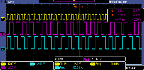
Note: probe 1 is the incoming signal from a function generator 
           probe 2 is the gpio pin being toggled 

At the 100 Hz frequency I tested, the interrupt doesn't trigger often enough and misses most of the incoming edges that it should be detecting. 

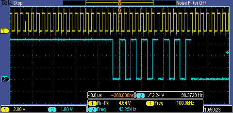
When the frequency is raised to the 100 kHz range, the interrupt triggers several times, drops out, then triggers several times again. The following image shows when the interrupt is toggling the gpio pin 

There is also noticeable latency in the first interrupt, here it is 8.92 microseconds 

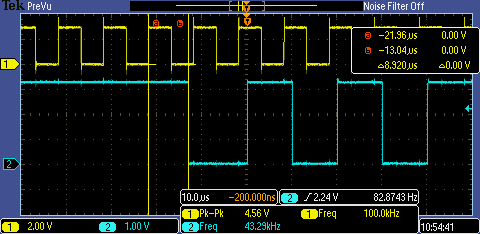
But each successive toggle (until the interrupt stops triggering for a random amount of time) has a latency of about 1.7 - 1.9 microseconds after the nearest edge. 

Any advice on what to do? I am about to attempt using a gpio interrupt to detect the incoming edges to see if that has any affect. I have also tried using a different pin (PB4) to detect the incoming edges using the same capture peripheral, which yielded the same results... 

Many thanks for your time! 

  • I haven't spent time with the capture modes but a couple of questions come to mind

    • Have you calculated what the expected values will be for your target frequency?
    • Why are you using a separate timer rather than the capture?
    • Where are you toggling the output pin (which interrupt)? Better than a toggle BTW would be to set the pin on entry and clear it on exit. Do this for both interrupts (separate pins obviously). You will gain a lot of information if you do that.

    Robert

  • Genovevo,

    You may find the message I just wrote on this thread useful for your frequency measurement strategy:

    e2e.ti.com/.../557130

    Trying to quickly service an interrupt and poll a timer value can be imprecise, and it will get worse when you add more functionalities and interrupts to your code.
  • Hi! Thanks for your reply!

    1) I did calculate the values I would be expecting, I get very close to the number of counts that I should be getting while I'm in the higher frequencies (50 kHz - 150 kHz). The problem I'm more focused on is why the interrupt seems to not be generating or triggering at the lower frequencies (100 - 200 Hz).

    2) I was at one point attempting to use the capture to do this, but I had an issue where it wouldn't generate an interrupt when the timer rolled over, and I wasn't getting valid data. I'm still trying to figure that out, but using one timer that runs freely seemed to give a better result.

    3) I'm toggling the output pin in Timer1IntHandler() where it says GPIOPinWrite(...). The goal was to have it toggle every time this interrupt is called. The waveform images I included show the results of that, where my issue is that something seems to be blocking the interrupt for large amounts of time. I am currently trying your trick, but in different parts of the software to see if there is something blocking operation elsewhere.

    If I can figure out how to get a larger resolution out of Timer 2, my results at the lower frequencies would be much more accurate. I tried using a prescaler, but I wasn't setting it correctly. Here is the code I used:

    TimerConfigure(TIMER2_BASE, TIMER_CFG_A_PERIODIC);
    TimerPrescaleSet(TIMER2_BASE, TIMER_A, 128);
    TimerLoadSet(TIMER2_BASE, TIMER_A, 65535);

    Do you know if this is a valid way to set a prescale or if I need another line somewhere?

    Thank you very much for your help!
  • One other thing I should be noting is that I'm going to try using the gpio pin to generate an interrupt as opposed to using the edge time capture to do this. I don't know how well this will work but will keep y'all posted!
  • Bruno Saraiva,

    Thank you for your reply and that information. I'm not entirely sure I could implement that solution with my level of experience with this part.
  • Genovevo,

    Do it step by step...

    First, do exactly what you wrote above: configure the signal input pin as GPIO, not as timer. Inside the interrupt, read the value of a continuous timer and do the math.

    (Using small loads to the timer seems weird... Use the timer as 32bit and configure it all the way to 0xFFFFFFFF. If you do that, you can always subtract new_value from old_value and will have the correct elapsed ticks.)

    When you are inspired to work with DMA (takes more than 5 minutes to learn...), you can try to make the DMA do the transfer of the GPIO and the timer value for you. By the way, if you are reading frequency and not duty, you don't even have to worry about the pin status.

    Back one step: you can still use the timer for your exercise. No need to use 2 times, as Robert pointed out before: leave one full-count timer running, and configure it to interrupt on edge. There are two counting registers on the timers: one stores the running time, and keeps changing every clock cycle while the timer is enabled. The other register freezes when the capture event occurs, so when you read it a bit later, the number there will be exactly the one you need.

    Ciao!
  • Genovevo Martinez said:
    1) I did calculate the values I would be expecting, I get very close to the number of counts that I should be getting while I'm in the higher frequencies (50 kHz - 150 kHz). The problem I'm more focused on is why the interrupt seems to not be generating or triggering at the lower frequencies (100 - 200 Hz).

    Did you do the calc at 100Hz? What do you get compared to your 64K timer period?

    Genovevo Martinez said:
    The goal was to have it toggle every time this interrupt is called

    Set/clear gives you more information. One important piece that you are missing is how long you are in the interrupt. And if you do the same in both interrupts you get phasing information as well.

    Robert

  • I've got an update with some success! 

    When playing around with placing another toggle pin at different parts of the code to see what was slowing down my process I found out that it would toggle and hold where I had a breakpoint that was set up to update the expressions view on the Code Composer Debug Mode. 

    Here is an image of the new waveform 


    Probe 3 is the new toggle pin, which can be ignored right now. But Waveform 2 is triggering at 1/2 the frequency of the input waveform(1) as it should be. So I suspect that updating the expressions view is what was holding up the processor. 

    Now I just need to figure out making each timer tick wider so I don't get so much rollover at these frequencies. The approach seems to be doing this with a prescale on the timer that I'm monitoring, any advice is appreciated! I'm pouring through the other forums as well here, but I'm danger close to the solution! 

    Thank you very much!