This thread has been locked.

If you have a related question, please click the "Ask a related question" button in the top right corner. The newly created question will be automatically linked to this question.

Two ports initialised - Causing my programme to crash

Hello,

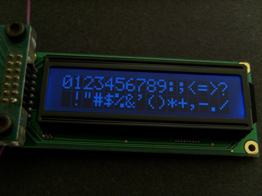
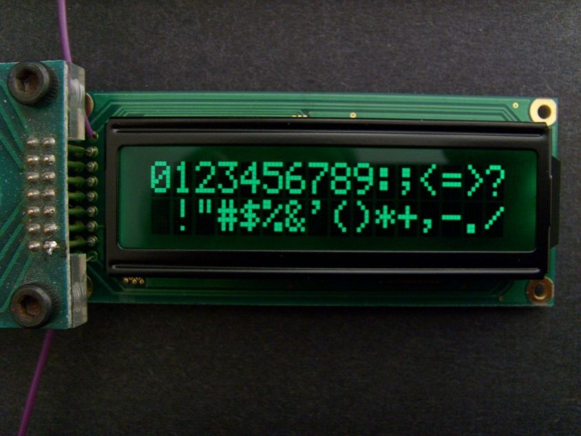
I am working on getting an LCD display to work with my Tive Tm4C , I have initialised PortA pins 2&3 which I will be using for the RS and enable line and I have initialised PortB pins 2,3,4,5 for the DB lines of the LCD as I am using it in 4-bit mode.

My problem comes when I used both ports together, for example to check they were working fine I had a simple function light up some LEDS, this worked fine for PortA, I went ahead and initialised PortB and tested it the same way and it was fine. However, if I initialise both ports and get them to output my programme crashes.

#define GPIO_PORTA_DATA_R (*(( volatile unsigned long*)0x400043FC))
#define SYSCTL_RCG2_R (*(( volatile unsigned long*)0X400FE108))
#define GPIO_PORTA_AMSEL_R (*(( volatile unsigned long*)0X40004528))
#define GPIO_PORTA_PCTL_R (*(( volatile unsigned long*)0X4000452C))
#define GPIO_PORTA_DIR_R (*(( volatile unsigned long*)0X40004400))
#define GPIO_PORTA_AFSEL_R (*(( volatile unsigned long*)0X40004420))
#define GPIO_PORTA_DEN_R (*(( volatile unsigned long*)0X4000451C ))

#define GPIO_PORTB_DATA_R (*(( volatile unsigned long*)0X400053FC))
#define GPIO_PORTB_AMSEL_R (*(( volatile unsigned long*)0X40005528))
#define GPIO_PORTB_PCTL_R (*(( volatile unsigned long*)0X4000552C))
#define GPIO_PORTB_DIR_R (*(( volatile unsigned long*)0X40005400))
#define GPIO_PORTB_AFSEL_R (*(( volatile unsigned long*)0X40005420))
#define GPIO_PORTB_DEN_R (*(( volatile unsigned long*)0X4000551C ))

//GPIO definitions
#define PA2 (*(( volatile unsigned long*)0x40004010)) //Connected to EN
#define PA3 (*(( volatile unsigned long*)0x40004020)) //Connected to RS
#define PB (*(( volatile unsigned long*)0x400050F0)) // Pins PB2,PB3,PB4,PB5 connected to DB4,DB5,DB6,DB7

void PortA_Init(void) {

volatile unsigned long delay;

SYSCTL_RCG2_R |=0x00000001; //set bit 0 for clock on port A
delay = SYSCTL_RCG2_R; //delay
GPIO_PORTA_AMSEL_R &=~ 0x0000000c; //disable analogue function
GPIO_PORTA_PCTL_R &=~0x0000FF00; //GPIO clear bits 8-11 for PA2 and 12-15 for PA3
GPIO_PORTA_DIR_R |=0x0c; //set bits 2 and 3
GPIO_PORTA_AFSEL_R &=~0x0c; //no alternate function
GPIO_PORTA_DEN_R |=0x0c; //enable pins PA2 and PA3

}

void PortB_Init(void) {

volatile unsigned long delay;

SYSCTL_RCG2_R=0x00000002; //set bit 1 for clock on port B
delay = SYSCTL_RCG2_R; //delay
GPIO_PORTB_AMSEL_R &=~ 0x0000003C; //disable analogue function clear bits 2,3,4,5
GPIO_PORTB_PCTL_R &=~0x00FFFF00; //GPIO clear bits 8-11 for PB2 12-15 for PB3 16-19 PB4 20-23 PB5
GPIO_PORTB_DIR_R |=0x3c; //set bits 2,3,4,5
GPIO_PORTB_AFSEL_R &=~0x3c; //no alternate function
GPIO_PORTB_DEN_R |=0x3c; //enable pins PA2 and PA3

}

Also a link to the project files here

  • Hello Harry,

    There is a know issue on the RCGC2 register. Also for Port B Init you are using RCGC2 = 0x2 and for Port A Init you are using RCGC2 |= 0x1. If the Port A init comes after Port B init then it is OK, but when Port B init comes after port A then the Port A would be clock disabled.

    I would suggest using TivaWare API's which takes care of such issues.
  • Hello, thank you for your assistance, I can see now why it wasn't working as I was clearing the bit. IT is working now thanks.

    Could I ask you another question? I am setting up the 16x2 LCD in 4-bit mode, so I will require 6 ouput pins altogether. I was planning on using PA2 for the enable line and PA3 for RS. I was then going to use PB0,PB1,PB2 & PB3 to write to the 4 data pins on the LCD. Would this be ok?

    My knowledge so far is a course very similar to the edX programme, I have so far not covered API's though I intend to once I finish my course.


    Regards
  • In addition to the (seriously) understated, "Ban DRM" poster's use of "4 Bit Lcd" code is SURE to cause "pain/suffering." Eight bit code is MUCH more forgiving - Tiva (not Tive) Ports ARE 8 bits wide - unwise to trade 4 GPIO for added complexity.

    As always - Text Lcd users must (somewhat) comply w/LCD Initialization AND must provide the proper voltage to pin Vo.
    48 hour data access suggests (very) wishful thinking by poster...
  • One more vote in favour of avoiding DRM. You not only make your life more difficult, you make it more difficult for others to help you which makes your life yet more difficult.

    Robert
  • Hello Harry,

    First of all you need not use a bit banged approach when larger panels with serial modes exist. Others have tried the approach and got the panel to work, not without the perils of the timing parameters associated with the panel.
  • Is DRM to do with how I have initialised Ports A&B? That is the only way I know how to do it from my university course and I believe it is the way it has to be done for my univeristy task. The same goes for 4-bit LCD mode, it is one of the requirements of the projects unfortunately.

    Thanks

  • Just to add, this is what I have done so far. I used a combination of a guide I found

    Here
    learningmsp430.wordpress.com/.../

    The data sheet for the Hitachi driver
    www.sparkfun.com/.../HD44780.pdf

    Set my screen up according to this pin layout
    www.powertipusa.com/.../pc1602f.pdf

    Unfortunately I can't see anything on my display, I'm not sure if this is down to an initialisation error or a faulty unit(There's no backlight or anything)

    This is my file currently
    expirebox.com/.../4a35300156e82a0a1a104e1709b1bef0.html

    I have used PA2 for enable and PA3 for RS
    PB0-PB3 have been used to make it easier to address the pins DB4-DB7


    Regards
  • Earlier I wrote of the requirement for a proper voltage applied to Text Lcd's pin, "Vo."   You've not responded to that direction.   Proper voltage setting of pin Vo occurs when the pixel field is (just) visible after successful display initialization.   It is most convenient to employ a potentiometer so that you may quickly/easily adjust voltage Vo.   (pot swings between ground and (usually) 3V3.)

    Again - as noted earlier - Lcd initialization is critical - and made even more so when one ventures into 4 bit mode.   I've presented - several times - extracts from the "Father of text Lcd Controllers, HD44780" which reveal (both) easy "8 bit" and uber demanding "4 bit."

    As a small tech biz owner - and having past been fortunate enough to co-found - take an earlier tech firm public - I'd ask your course director if, "Time spent in Development" is of (any) concern?   Your path has been markedly obstructed by their two (unwise, ill-considered) demands:

    • restrict code development to (only) DRM
    • restrict Text Lcd interface to the far more complex, and noise sensitive, "4 bit mode"

    The claim is (always):  "Students learn better" via DRM.   And that's long been proven false!    You/most all (similar) others have resorted to (mostly) unproductive "net-searches" - which prove SO effective that you wind up here - w/little achieved.   (thank you University instructors)  

    Unmentioned is your access to (modern) test gear - such as multi-channel oscilloscope, logic analyzer.   (might your university seek to (still further) cripple your efforts - by disallowing both - supplying you w/a single Led to serve as a "1 bit" output monitor, only?    Such would be in keeping w/their earlier "anti-progress" declaration - would it not?)

    Restricted as you are you may consider:

    • employing a logic analyzer to monitor your 4 bit D-Bus and 2 bit Control-Bus   (in a pinch - 6 Leds may so serve)   Your first job is to insure that your "spectacularly enhanced learning" (only achieved via DRM) enables you to properly control MCU GPIO.
    • Once that's achieved - you need to carefully/methodically follow the uber complex 4 bit initialization instructions - presented by HD44780 and/or newer clones.   Both the data & timing between each instruction "must" comply w/the (very) strict 4 bit initialization specifications.   You'll have to "break" from the school's (apparent) "anti-progress" rule by employing a scope to insure timing requirements are met...

    One wonders if managers at the Tesla factory "burden" their engineers by forcing them to employ slide rules - and bypass critical other tech advances - so that their "learning" (too) is enhanced!

    Firms today compete globally - being LAST to market (surely the result of following your instructor's guidelines) is not famed for yielding the highest profit margin - more likely results in NO/ZERO profit margin!   (and somehow - that's been missed!)

    This vendor has a most excellent API - which is, "Tried, True, Tested" - which cannot be said of DRM - even such exalted DRM flowing from the pen of your instructors...   Blocking you/others from its presence, use & exploitation proves exceedingly difficult to justify.   (i.e. cannot be justified!)

    It is quite possible to study and learn via the API - nothing prevents you from examining Registers & Bit Positions - and the impact of each/every MCU instruction.   Perhaps more importantly - you've learned to, "exploit what's readily available" - satisfy the project's requirements - and be far better prepared for, 'Next."    Such skill - and awareness - prove vital to today's tech force.   Turning a "blind eye" to a, "Vastly Superior Approach" somehow seems counter-productive - and (very) ill-advised...

  • Yes, DRM describes what you've done so far (Direct Register Manipulation).

    You might want to make sure you are restricted to just that before making it a restriction you impose on yourself.

    It's not that long ago that DRM was definitely the right method to use. Vendor libraries were universally either such a thin wrapper on the registers that all they did was make code development more cumbersome or they were so restrictive in their abstractions that they were useful only for a very narrow application subset. To top it off they were usually buggy as well. Times have changed.

    Robert
  • Backlight suggests a power issue?

    Cb1 is a good source of hints on what to check for LCDs, note his suggestion on contrast voltage.

    An oscilloscope or logic analyzer will make debugging go a lot faster as will use of TDD.

    Robert
  • Robert Adsett72 said:
    An oscilloscope or logic analyzer will make debugging go a lot faster as will use of TDD.

    Indeed - yet to make the "torture" consistent - should not ALL, "Advanced, Effective" methods be disallowed?

    Poster should read the Lcd spec (w/blindfold lessened/removed - should that be allowed) and must note that MCU GPIO is insufficient to power the *usual" multi-Led backlight...

    Staff/I question if this student was not forced to, "Self Power" his board and Led light (via pedaling a crude E-Bike) - so that he could (endlessly) page thru the MCU manual - and get each/every bit w/in multiple registers - "just right!"     (such is described - wishfully - as "Real Learning!")   (i.e. learning what to AVOID...)

  • Thanks for the advice. To address some of the questions

    I do have Vo connected via a potentiometer that goes between 3.3V and GND - Unfortunately there are no signs of life on the display, I even connected Vo to 3.3V and GND directly to confirm pot wasn't faulty.

    Others have had the LED backlight working on 3.3V despite the data sheet request for 4.2V, which makes me think the unit itself is broken.

    I believe I am definitely tied to using DRM the 4bit mode is ambiguous, would it really make things that much easier? As I'd be willing to go that route and argue my case for choosing it. Though wouldn't 8-bit still fall prey to the timing perils?

    Could you point me in the direction of "Father of text Lcd Controllers, HD44780" as I haven't been able to find it via Google, I would like to learn about 8-bit operation.

    Regards

  • Hi,

    I did not read your code - but from your description the R/W LCD pin is missing to be connected to the micro. And it needs to be low to write, hence display. Reading the display is used seldom, I never used it. And the 4 bit mode was useful to me when not enough available pins.

    The main problems to be solved are the delays at startup and when working. 

  • Hi, I forgot to mention R/W - I grounded the pin as I would only be using the LCD is write mode.

    For the delays I have used Systick as I learned it from edX - I have used the 16MHz crystal for accuracy and set the PLL to run at 80Mhz. Therefore for delays I have calculated the number of clock cycles

    ie for a 4.1ms delay I did

    4.1*10^-3
    ________ =328000 cycles
    12.5*10^-9


    Is this the method you used?


    Thanks
  • Hi,

    I have used the same device P1602 some six years ago, with another brand micro and the delays were software, similar to SysCtlDelay in Tiva.

    You can attach your .c file here, to be inspected by the community, downloading a .zip from another site may be harmful.

    Some more hints : the device is a +5V one,  hope you noticed that, the data sheet request levels  >3.3V.

    Check also the adjust voltage.

  • #include "main.h"


    int main(void) {
    	PLL_Init();
    	SysTick_Init();
    	PortB_Init();
    	PortA_Init();
    
    	Lcd_Init();
    	
    while(1) {
    	
    	//led();


    	SysTick_Wait(1200000);
    	
    
    	SysTick_Wait(1200000);
    
    		
    	SysTick_Wait(1200000);
    
    	
    		SysTick_Wait(1200000);
    
    	
    }
    }


    void PLL_Init(void){
      // 0) Use RCC2
      SYSCTL_RCC2_R |=  0x80000000;  // USERCC2
      // 1) bypass PLL while initializing
      SYSCTL_RCC2_R |=  0x00000800;  // BYPASS2, PLL bypass
      // 2) select the crystal value and oscillator source
      SYSCTL_RCC_R = (SYSCTL_RCC_R &~0x000007C0)   // clear XTAL field, bits 10-6
                     + 0x00000540;   // 10101, configure for 16 MHz crystal
      SYSCTL_RCC2_R &= ~0x00000070;  // configure for main oscillator source
      // 3) activate PLL by clearing PWRDN
      SYSCTL_RCC2_R &= ~0x00002000;
      // 4) set the desired system divider
      SYSCTL_RCC2_R |= 0x40000000;   // use 400 MHz PLL
      SYSCTL_RCC2_R = (SYSCTL_RCC2_R&~ 0x1FC00000)  // clear system clock divider
                      + (4<<22);      // configure for 50 MHz clock 
    	//*** YOU CAN CHANGE The 50 MHz Frequency above, by changing the Dividor "7" to 
    	//*** any desired frequency, i.e (4<<22) makes it 80 MHz etc. ..
    	
      // 5) wait for the PLL to lock by polling PLLLRIS
      while((SYSCTL_RIS_R&0x00000040)==0){};  // wait for PLLRIS bit
      // 6) enable use of PLL by clearing BYPASS
      SYSCTL_RCC2_R &= ~0x00000800;
    }
    
    void SysTick_Init(void){
      NVIC_ST_CTRL_R = 0;                   // disable SysTick during setup
      NVIC_ST_RELOAD_R = 0x00FFFFFF;        // maximum reload value
      NVIC_ST_CURRENT_R = 0;                // any write to current clears it             
      NVIC_ST_CTRL_R = 0x00000001;          // enable SysTick with core clock
    }


    void PortA_Init(void) {
    	
    	volatile unsigned long  delay;
    	
    	SYSCTL_RCG2_R |=0x00000001; //set bit 0 for clock on port A
    	delay = SYSCTL_RCG2_R;         //delay
    	GPIO_PORTA_AMSEL_R &=~ 0x0000000c;  //disable analogue function
    	GPIO_PORTA_PCTL_R &=~0x0000FF00;    //GPIO clear bits 8-11 for PA2 and 12-15 for PA3
    	GPIO_PORTA_DIR_R |=0x0c; //set bits 2 and 3
    	GPIO_PORTA_AFSEL_R &=~0x0c;  //no alternate function
    	GPIO_PORTA_DEN_R |=0x0c;         //enable pins PA2 and PA3
    	
    }
    
    
    void PortB_Init(void) {
    	
    	volatile unsigned long  delay;
    	
    	SYSCTL_RCG2_R=0x00000002; //set bit 1 for clock on port B
    	delay = SYSCTL_RCG2_R;         //delay
    	GPIO_PORTB_AMSEL_R &=~ 0x0000000F;  //disable analogue function clear bits 0,1,2,3
    	GPIO_PORTB_PCTL_R &=~0x0000FFFF;    //GPIO clear bits 0-3 for PB0  4-7 for PB1 8-11 PB2 12-15 PB3
    	GPIO_PORTB_DIR_R |=0x0F; //set bits 0,1,2,3
    	GPIO_PORTB_AFSEL_R &=~0x0F;  //no alternate function
    	GPIO_PORTB_DEN_R |=0x0F;         //enable pins PB0-PB3
    	
    }


    #include "LCD.h"
    
    
    void SysTick_Wait(unsigned long wait){
     NVIC_ST_RELOAD_R = wait-1;  // number of counts to wait
      NVIC_ST_CURRENT_R = 0;       // any value written to CURRENT clears
     while((NVIC_ST_CTRL_R&0x00010000)==0){ // wait for count flag
      }
    }


    void Lcd_Init(void) {
    	
    	lcdEN =0; //lcdEN intialised at 0
    	lcdDB=0; //lcdDB initialised at 0


    	SysTick_Wait(1200000); //wait 15ms
    	lcdRS=0; //RS set to 0 for instruction RW pin grounded
    	lcdDB=0x03;  //write 0011 to DB Pins
    	lcdENPulse();//Command latched by pulsing EN line for 500ns
    	
    	SysTick_Wait(328000); //wait 4.1ms
    	lcdRS=0; 
    	lcdDB=0x03;
    	lcdENPulse();
    	
    	SysTick_Wait(8000); //wait 100us
    	lcdRS=0;
    	lcdDB=0x03;
    	lcdENPulse();
    	
    	SysTick_Wait(328000); //wait 4.1ms
    	lcdRS=0;
    	lcdDB=0x02;
    	lcdENPulse();
    	
    	lcdWriteCommand(0x28);  //set 4 bit mode, 2 lines, 4x8 font
    	lcdWriteCommand(0x0F);  //set display,cursor and cursor blink on
    	lcdWriteCommand(0x06);  //set cursor to increment and display not to shift


    }


    void lcdENPulse(void) {
    
    	lcdEN = 0x04; //EN set high by setting PA2 high
    	
    	SysTick_Wait(40);  //500ns wait
    	
    	lcdEN=0;  //EN set low
    	
    
    }
    
    void lcdWriteCommand(unsigned char cmd) {
    	
    	lcdRS=0; //RS set low RW pin grounded
    	SysTick_Wait(3200);  //40us wait
    	lcdDB=((cmd & 0xF0)>>4);  //High nibble sent
    	lcdENPulse(); //Enable line pulsed to latch command
    	SysTick_Wait(400000); //5ms wait
    	
    	lcdDB=(cmd & 0x0F); //low nibble sent
    	lcdENPulse();  
    	SysTick_Wait(400000); //5ms wait
    	
    }


    LCD.hmain.h

  • Thanks, i've added my files - As for the 5V , I believe it should run from 3.3V, according to my teacher they had been used before with the Tiva board.
  • As for the 5V , I believe it should run from 3.3V, according to my teacher they had been used before with the Tiva board.

    I suggest to take a teacher's statement with a grain of salt. As a saying goes (can't recall the author): "Those who can, do. Those who can't, teach."

    Connecting a 5V and 3.3V device <<seems>> to work if the 3.3V device pins are 5V-tolerant, at least in one way. But signalling from the 3.3V to the 5V side is either shaky, or does not work, because the H level output of a 3.3V device and the input threshold of the 5V device are not matching.

    Open-Drain with pull-up to 5V would work (if the pin is specified as 5V-tolerant).

  • Hello Harry,

    Might it not be worthwhile to borrow another LCD panel and check if indeed the issue is with the LCD panel?
  • Hi,
    Some comments about your code:
    a) Refer to fig. 25 in HD774xx data sheet and try to modify your code to comply with the waveform, i.e set RS, wait for tAS (setup time, = 40ns!) which can be avoided since it is accomplished by the execution of next C line code; set E (not pulse), set nibble, wait for 500ns, clear E, wait for 500ns and then repeat for next nibble. The
    datasheet shows the timing parameters in ns, not micros.
    b) You need a corresponding lcdWriteData() function, to send data to the display; do not hesitate to write two rows of characters in your while(1) loop in main.

    c) Second f.m opinion!

  • Hi, yes tomorrow I will be going into university where I can test my screen and get a replacement necessary - I thought I'd put my code up in the meantime for feedback as i'd be suprised if I got it correctly on my first go :)

    Thanks
  • Harry James said:
    Others have had the LED backlight working on 3.3V despite the data sheet request for 4.2V

    Silent here is the current available at that voltage.    These Lcds most always employ an array of Leds - and the 4.2V (usually) results from 2 Leds wired in series - which "does" require (near) 4V2 to illuminate fully.   It is also common to encounter multiple such Led "strings" - which demands even higher current.

    Note too that newer Leds (white & blue) require higher voltage to fully illuminate.   (old yellow-green "standard" pretty much established the 2V1 single Led level.)

    You cannot properly power the LCD's backlight from an MCU's GPIO.

    The fact that (others) may have succeeded (only) proves useful if their Lcd is a full equivalent of yours!   (not just "sharing" a (fairly generic) part number.)   And (that) may "not" have been established... 

    In years past (decades really) I designed a spring loaded, "bed of nails" test set - which enabled the quick/eased testing of such Text Lcds - requiring NO/ZERO soldering!    This proved a great hit w/clients - visual products such as these NEED to be seen in operation - and two such "bed of nails" testers enabled the "A-B" comparison of competing devices...    Pity your school has not made such an investment - which positively assures that your Lcd is functional...

  • Harry James said:
    As for the 5V , I believe it should run from 3.3V, according to my teacher they had been used before with the Tiva board.

    That's a rather mind-boggling statement.

    Robert

  • f. m. said:
    I suggest to take a teacher's statement with a grain of salt. As a saying goes (can't recall the author): "Those who can, do. Those who can't, teach."

    "And those who can't teach administrate" if I remember the triad correctly.

    To be fair teaching is a completely different skill set from doing (particularly the more complex tasks). So getting a teacher who is competent both at the task and at teaching can be an issue1. Being good at only one does the student a disservice and the student may not be in a position to judge until well into the process.

    Robert

    1 - Witness how few really good science teachers there are, ones who can teach the facts, the methodology and the reasons behind the methodology all without killing the curiosity so necessary for truly continually using and understanding it as life progresses.

  • Aha - so we've (killed) the teachers - and administrators - should not our (incorrectly) "Climate Obsessed, Re-Election at any/every cost, Politicians" join this merry band?
  • "And those who can't teach administrate" if I remember the triad correctly.

    I know that part, too. But it seemed not relevant for that very special case. But you are right - I have been in schools for 17 years, and witnessed very few good teachers with practical skills.

    And ( @cb1 ), with "administer", I especially include politicians. Which reminds me on the latest "election" Kabuki in the US of A, the Bablak/Hare book "Snakes in suits", and an old idiom of my native language: "To choose between the plague and cholera".

    But that is sliding off-topic ...

  • Perhaps - just a (bit) of a slide - but always ADDS Interest & shows "view of the world" far beyond, "My board DON'T WORK!"
  • And - arrives now (after mistaken entry to another thread):

    Rather than "hope, pray, guess" that your (likely) discount Display works - might a "more active" means prove superior?

    illustrated here is a method to, "Solderlessly Connect" - and quickly/easily - verify Display Operation.   (and may be employed repeatably)

    No funds/effort were spared in the creation of this "Display Solution. "    A  "binder clip" intended to hold sheets of paper is attached to a pcb which holds, "Spring-Loaded" Test Pins which are cabled to a small, ARM MCU.   Such enables, "No hands, Lcd testing!"    Different clips may be designed - fed from the same small MCU board - to accommodate a variety of displays employing different signal connections/types/pitches.

    This device, "Speeds, Eases & Enhances" the Test/Verification of multiple Displays - and eliminates all Soldering.  (almost all! - pay no attention to the 2 wired connections which service the, "R-G-B" Led Array Backlight.    (just ONE Lcd is shown - w/the backlight drive changed to alter color...)

    Crack staff photographer (promises) to consume (less) adult beverages prior to next, "shoot."    (promise was made earlier - iirc...)


  • Thank you, I collect my replacement LCD tomorrow, I have read the sheet and will make the changes and let you know how it goes :)

    Regards
  • f. m. said:
    I know that part, too. But it seemed not relevant for that very special case. But you are right - I have been in schools for 17 years, and witnessed very few good teachers with practical skills.

    And I've seen the reverse fairly frequently as well. Highly competent technically, not able to teach.

    Robert

  • Hi, I finally got a replacement panel and the good news is it is showing signs of life - I ran my initialisation code prior to making your suggested changes and I get a flashing cursor in the top left position. People I have spoken to have said this is a sign that the initialisation process has worked, however when I go to write a string or character to the screen I errors, such as the cursor disappearing or moving position?

    I checked my delays were accurate using the logic analyser at my university, this came out accurate, does this sound like an intitialisation issue or a problem with my code for adding a character to the screen?

    Thanks

  • Hi,
    To ask your latest question: it is quite normal to have the cursor moved to the next position after a character is sent and displayed, and dissappear at the last line
    position. You have a command to show/hide the cursor, check the data sheet.

    To remove any doubt about your previous display module, please do the folowing: turn back the module, identify the HD chip and read the marking: if it is HD44780S, then for sure it is for 5V; if it is HD44780U, then it can work at 3.3V. If other marking, check the real data sheet. In the lasts twenty years I did not heard about burnt/wrong display nodules, used many displays from various brands, and the production lines and service departments never complained about such things.

    Also about your code: two delays of 5ms are very big, unusual, maybe good for scrolling, try to lower, minimum 40us - normally after writing a character, you must check bit7 of the display for completion, but this can be replaced by a small delay.

    Check also this site, other users posted code snippets using Tiva API.

  • Hi, I managed to resolve the issue, the error was in my writeData function where I had set the RS pin high, I had set it to 1 rather than setting the fourth bit high.It's now finally displaying text!

    Cheers