This thread has been locked.

If you have a related question, please click the "Ask a related question" button in the top right corner. The newly created question will be automatically linked to this question.

CMSIS DSP continuous Data Processing and transmitting with TM4C129x MCU

Other Parts Discussed in Thread: TIDM-TM4C129POEAUDIO, TM4C129XNCZAD

Hi all,


Iam using TM4C1294XL launchpad and Iam trying to implement low pass filter function of CMSIS DSP Library.

I'am facing an issue of sending the filter output continuously via UART to another TM4C129x MCU which is running the TFT. I'am able to implement the filter but the data is being sent block by block to the other MCU due to which I'am getting unexpected results.

Iam using timer to trigger the ADC @ sampling rate of 256Hz.

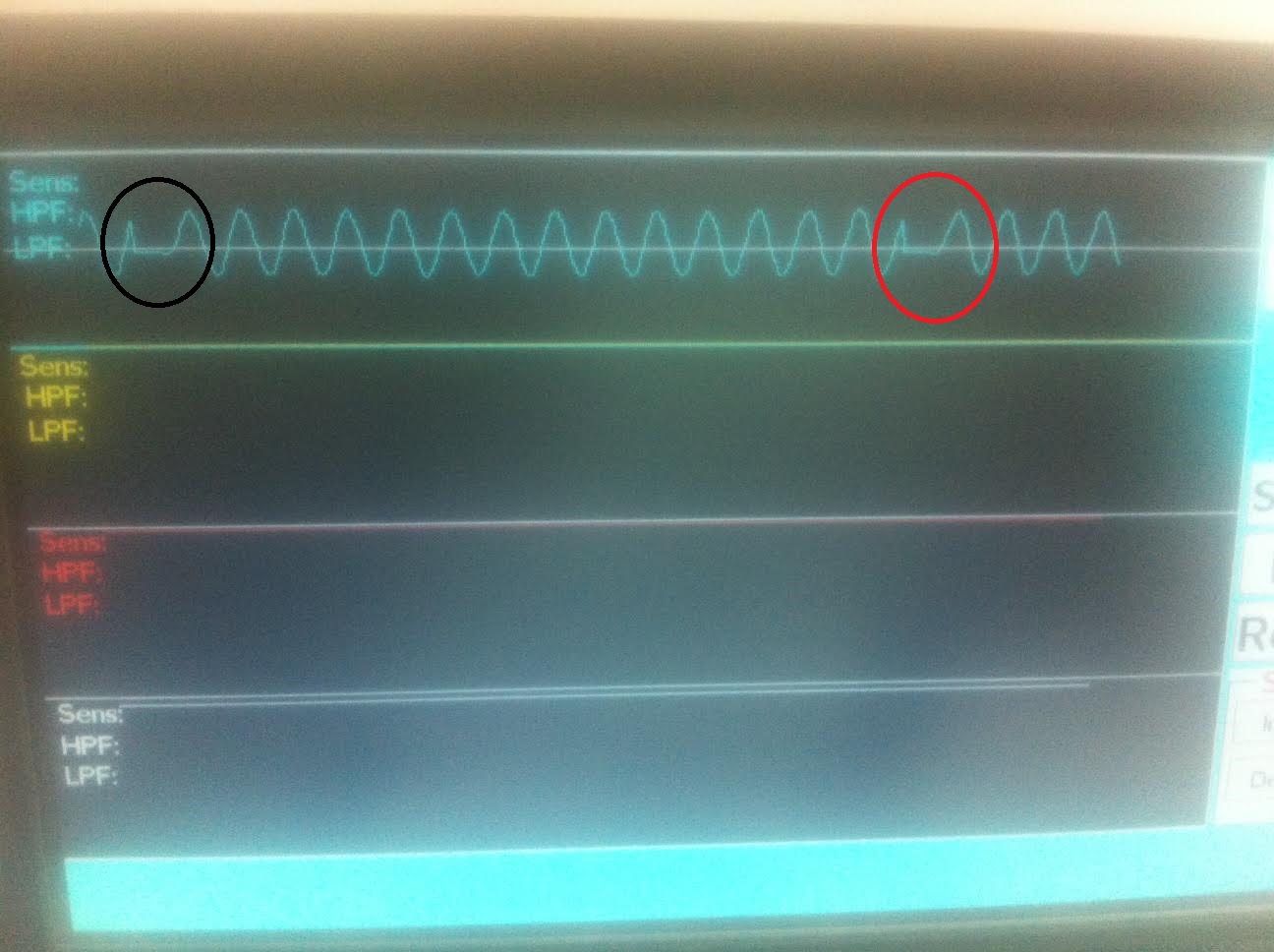
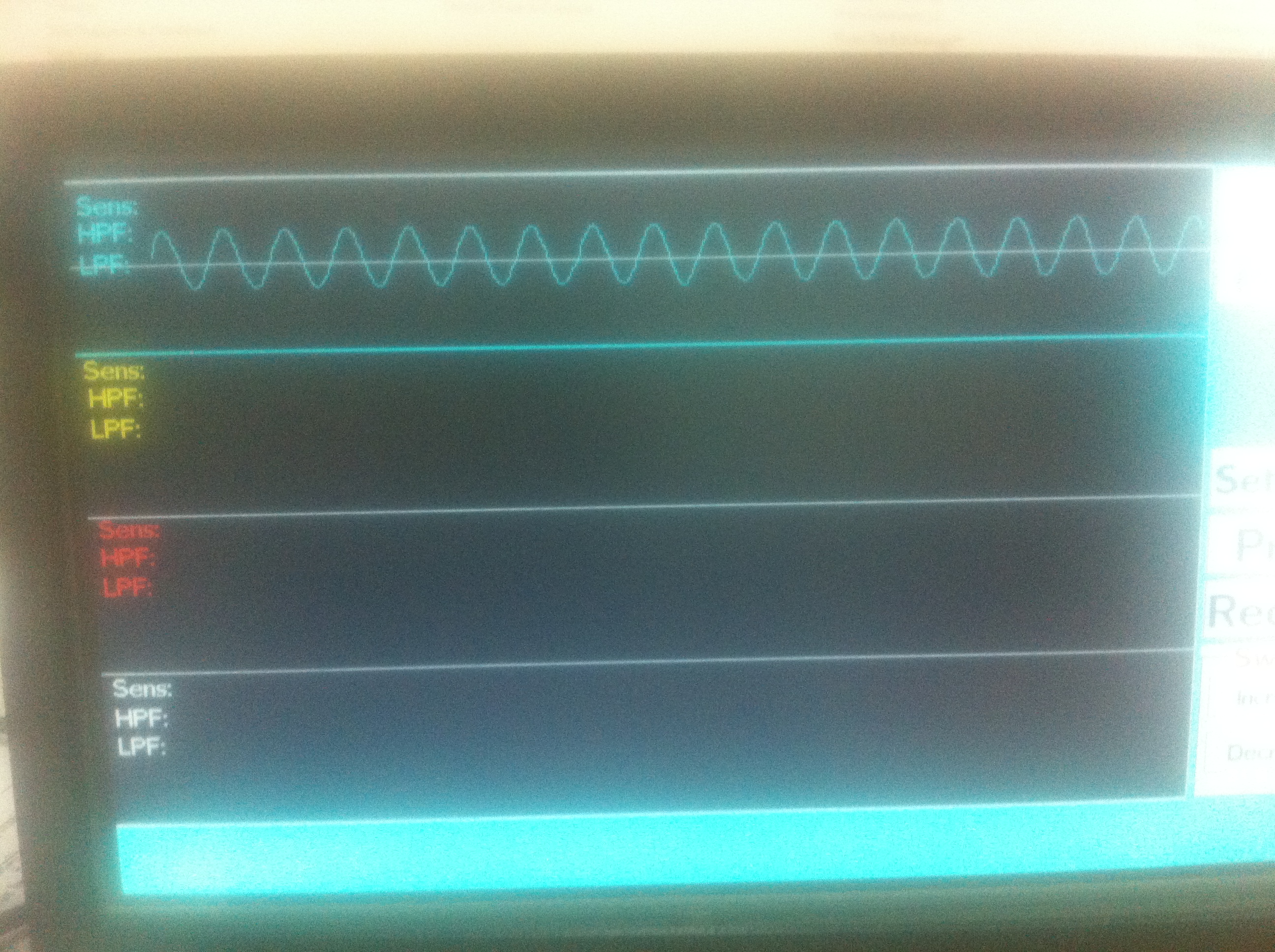
Input signal is sine wave with varying frequency between10-50Hz and the cutoff frequency is 30Hz.


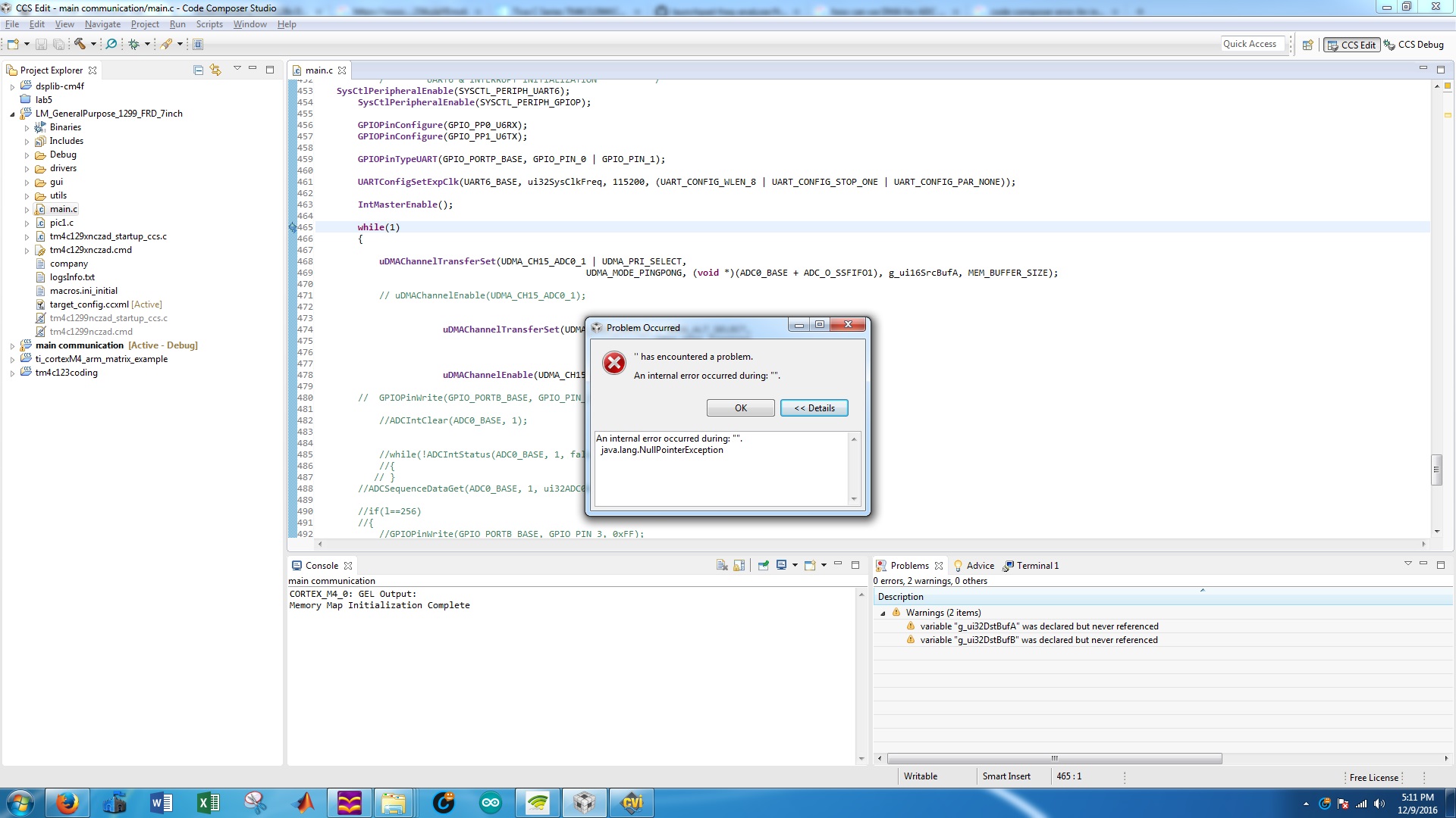
Below is the while(1) loop of my code for reading ADC & sending filter data.I've also attached the screen shot of the data plotting on TFT using Graphics library. It can be seen that the sine wave is not continuous.

Kindly help me to sort this issue

float32_t p[256];

#define TEST_LENGTH_SAMPLES  256

#define BLOCK_SIZE           128

#define NUM_TAPS              29

static float32_t firStateF32[BLOCK_SIZE + NUM_TAPS - 1];

float32_t testOutput[TEST_LENGTH_SAMPLES];

float32_t inputsamples[TEST_LENGTH_SAMPLES];


 arm_fir_instance_f32 S;


 float32_t  *inputF32, *outputF32;

uint32_t blockSize = BLOCK_SIZE;
uint32_t numBlocks = TEST_LENGTH_SAMPLES/BLOCK_SIZE;

void Timer0IntHandler(void)
{

    TimerIntClear(TIMER0_BASE, TIMER_TIMA_TIMEOUT);
 
    ADCSequenceConfigure(ADC0_BASE, 1, ADC_TRIGGER_TIMER, 0);
 
}

int main(void)
{


    FPULazyStackingEnable();

    FPUEnable();

    uint32_t ui32Period;


    uint32_t  l=0;


     int32_t CH1DATA ;

    inputF32 = &inputsamples[0];

    outputF32 = &testOutput[0];


    ui32SysClkFreq= SysCtlClockFreqSet((SYSCTL_XTAL_25MHZ | SYSCTL_OSC_MAIN | SYSCTL_USE_PLL | SYSCTL_CFG_VCO_480), 120000000);


 ********************ALL INITIALIZATION CODE OMITTED TO BE SPECIFIC TO THE ISSUE*********

        while(1)
        {
      
            ADCIntClear(ADC0_BASE, 1);


            while(!ADCIntStatus(ADC0_BASE, 1, false))
            {
            }
        ADCSequenceDataGet(ADC0_BASE, 1, ui32ADC0Value);

        if(l==256)
        {
            
            l=0;

            arm_fir_init_f32(&S, NUM_TAPS, (float32_t *)&firCoeffs32[0], &firStateF32[0], blockSize);

            for(i=0; i < numBlocks; i++)
            {
                arm_fir_f32(&S, inputF32 + (i * blockSize), outputF32 + (i * blockSize), blockSize);

            }


        }


        p[l] = (float32_t)ui32ADC0Value[0];
        p[l] = p[l] - (float32_t)0x0810;

        inputsamples[l]= p[l];


                                                                                UARTCharPutNonBlocking(UART6_BASE,'a'); //  To tell the other MCU to start plotting the incoming data.

                                                                                CH1DATA= (int32_t)testOutput[l]+ (int32_t)0x0810;


                                                                                al = CH1DATA & 0xF00;
                                                                                al = al>>8;
                                                                                ah = CH1DATA & 0xFF;


                                                                                UARTCharPutNonBlocking(UART6_BASE,ah);
                                                                                UARTCharPutNonBlocking(UART6_BASE,al);

                                                                            l=l+1;

        }

}


  • Hello Sumit

    Have you verified the duration of the processing and transfer is not the same as the missing signal time on the main MCU?
  • Hi Amit,

    Thank you for looking into my query.

    I dont know exaclty How to verify the duration of processing??

    How to manage the processing and transfer time simultaneously??

  • Hello Sumit,

    A simple method is to toggle GPIO's at the start and end of a function, that can be measured on a scope or a logic analyzer.

    In your code you are performing ADC capture using CPU. Off load it to the DMA with a ping pong mechanism. An example of this is shown in the TIDM-TM4C129POEAUDIO example where audio captured over ADC triggered by the timer is done using DMA. Once the DMA transfer of one buffer is done, the audio compression (in your case FFT) is done and data is handed off to the EMAC (in your case serial port).
  • Hi Amit,

    Is it Necessary to use DMA?? cannot be it implemented simply with arrays??
    I will have to study DMA though its not an issue because I really want to solve this issue no matter whatever I need to study.
  • Hello Sumit,

    The CPU can either process the FFT or it can be in a blocking while loop for ADC conversion or it can be in a blocking while loop for the UART transfer. Each of these will consume valuable CPU time to perform the continuous ADC conversion as expected. I would suggest using the GPIO toggle to first setup the experiment on processing time of each activity to match it up with the waveform discrepancy you are seeing.
  • Hi Amit,

    So i should try the below code

     if(l==256)

           {

               l=0;

    GPIO pin ON

               arm_fir_init_f32(&S, NUM_TAPS, (float32_t *)&firCoeffs32[0], &firStateF32[0], blockSize);

               for(i=0; i < numBlocks; i++)

               {

                   arm_fir_f32(&S, inputF32 + (i * blockSize), outputF32 + (i * blockSize), blockSize);

               }

    GPIO pin Off

    }

    and check the GPIO freq on Oscilliscope?

  • Hello Sumit

    Yes, somewhat like this around all the function except those where the ADC data is getting captured.
  • Hi Amit,

    As per your suggestion I tried using DMA for ADC data capture triggered by timer. I found one of your codes on the Forum dated 28th Oct,2016

    I read somewhere in the forum where you have told that we need to first configure the DMA, then ADC & in the end the TIMER.

    I've copied this code for my own sampling rate of 256Hz  but there are few issues in it.

    1). During complitaion it is giving me error - ../main.c", line 258: error: identifier "ADC_O_SSFIFO0" is undefined

    Iam not able to correct this error.


    2). How to copy the data from DMA  buffer to my input samples for CMSIS DSP Low pass filter. Also i need to typecast them to float32_t to be able to used by the filter.

    Below is My code, Kindly help

    #include <stdint.h>
    #include <stdbool.h>
    #include "inc/hw_memmap.h"
    #include "inc/hw_types.h"
    #include "inc/hw_udma.h"
    #include "driverlib/sysctl.h"
    #include "driverlib/gpio.h"
    #include "driverlib/pin_map.h"
    #include "driverlib/uart.h"
    #include "inc/hw_ints.h"
    #include "driverlib/interrupt.h"
    #include "driverlib/debug.h"
    #include "driverlib/adc.h"
    #include "driverlib/timer.h"
    #include "arm_math.h"
    #include <math.h>
    #include "driverlib/fpu.h"
    #include "driverlib/udma.h"
    //#include "math_helper.h"
    
    #pragma DATA_ALIGN(pui8DMAControlTable, 1024)
    uint8_t pui8DMAControlTable[1024];
    
    #define MEM_BUFFER_SIZE 1024
    static uint16_t g_ui16SrcBufA[MEM_BUFFER_SIZE];
    static uint16_t g_ui16SrcBufB[MEM_BUFFER_SIZE];
    static uint32_t g_ui32DstBufA[MEM_BUFFER_SIZE];
    static uint32_t g_ui32DstBufB[MEM_BUFFER_SIZE];
    
    
    void uDMAErrorHandler(void)
    {
        uint32_t ui32Status;
    
        ui32Status = uDMAErrorStatusGet();	// Check for uDMA error bit
        if(ui32Status)						// If there is a uDMA error
        {
            uDMAErrorStatusClear();			//Clear the error status
        }
    
    }


     //uint32_t CH1DATA=0;
    volatile uint32_t CH2DATA=0;
    volatile uint32_t CH3DATA=0;
    volatile uint32_t CH4DATA=0;
    
    volatile uint32_t CH1ADC=0;
    volatile uint32_t CH2ADC=0;
    volatile uint32_t CH3ADC=0;
    volatile uint32_t CH4ADC=0;
    
    volatile int32_t al=0;
    volatile int32_t ah=0;
    volatile uint32_t bl=0;
    volatile uint32_t bh=0;
    volatile uint32_t cl=0;
    volatile uint32_t ch=0;
    volatile uint32_t dl=0;
    volatile uint32_t dh=0;
    int flag = 0;
    bool flag1 = false;
    bool flaglp = false;
    uint32_t i=0 ,j=0, k=0,l=0, m=0;
    uint32_t ui32ADC0Value[4];
    float32_t p[256];
    float32_t q[256];
    uint32_t r[128];
    volatile uint32_t s[1000];
    q31_t t[128];
    volatile uint32_t u[128];
    volatile uint32_t v[128];
    volatile uint32_t w[128];


    uint32_t ui32SysClkFreq;
    
    #define TEST_LENGTH_SAMPLES  256
    
    #define BLOCK_SIZE           128
    
    #define NUM_TAPS              29
    
    static float32_t firStateF32[BLOCK_SIZE + NUM_TAPS - 1];
    
    float32_t testOutput[TEST_LENGTH_SAMPLES];
    
    float32_t inputsamples[TEST_LENGTH_SAMPLES];
     arm_fir_instance_f32 S;
     float32_t  *inputF32, *outputF32;
    
    
     /****** coeffecients for 256hz sampling rate******/

    /*const float32_t firCoeffs32[NUM_TAPS] = {
            -0.0014,   -0.0003,    0.0019,    0.0051,    0.0071,    0.0041,   -0.0067,   -0.0222,   -0.0326,   -0.0242,    0.0128,    0.0767,    0.1512,

            0.2114,    0.2345,    0.2114,    0.1512,    0.0767,    0.0128,   -0.0242,   -0.0326,   -0.0222,   -0.0067,    0.0041,    0.0071,    0.0051,

             0.0019,   -0.0003,   -0.0014

    };*/ uint32_t blockSize = BLOCK_SIZE; uint32_t numBlocks = TEST_LENGTH_SAMPLES/BLOCK_SIZE; void ADCseq1Handler(void) { uint16_t ui16Index; TimerDisable(TIMER0_BASE, TIMER_A); uint32_t ui32Status = ADCIntStatus(ADC0_BASE, 1 , false); uint32_t ui32Mode; ADCIntClear(ADC0_BASE, 1); ADCIntClearEx(ADC0_BASE, ADC_INT_DMA_SS1); ui32Mode = uDMAChannelModeGet(UDMA_CHANNEL_ADC0 | UDMA_PRI_SELECT); if(ui32Mode == UDMA_MODE_STOP) { uDMAChannelTransferSet(UDMA_CHANNEL_ADC0 | UDMA_PRI_SELECT, UDMA_MODE_PINGPONG, (void *)(ADC0_BASE + ADC_O_SSFIFO0), g_ui16SrcBufA, MEM_BUFFER_SIZE); for(ui16Index=0;ui16Index<MEM_BUFFER_SIZE;ui16Index++) { if((g_ui16SrcBufA[ui16Index] < 2000) && (ui16Index%2 == 0)) { flag++; } if((g_ui16SrcBufA[ui16Index] > 2000) && (ui16Index%2 == 1)) { flag++; } } } ui32Mode = uDMAChannelModeGet(UDMA_CHANNEL_ADC0 | UDMA_ALT_SELECT); if(ui32Mode == UDMA_MODE_STOP) { uDMAChannelTransferSet(UDMA_CHANNEL_ADC0 | UDMA_ALT_SELECT, UDMA_MODE_PINGPONG, (void *)(ADC0_BASE + ADC_O_SSFIFO0), g_ui16SrcBufB, MEM_BUFFER_SIZE); for(ui16Index=0;ui16Index<MEM_BUFFER_SIZE;ui16Index++) { if((g_ui16SrcBufA[ui16Index] < 2000) && (ui16Index%2 == 0)) { flag++; } if((g_ui16SrcBufA[ui16Index] > 2000) && (ui16Index%2 == 1)) { flag++; } } } uDMAChannelEnable(UDMA_CHANNEL_ADC0); TimerEnable(TIMER0_BASE, TIMER_A); } int main(void) { FPULazyStackingEnable(); FPUEnable(); uint32_t ui32Period; int32_t CH1DATA ; inputF32 = &inputsamples[0]; outputF32 = &testOutput[0]; ui32SysClkFreq= SysCtlClockFreqSet((SYSCTL_XTAL_25MHZ | SYSCTL_OSC_MAIN | SYSCTL_USE_PLL | SYSCTL_CFG_VCO_480), 120000000); /******* DMA INITIALIZATION***********/ SysCtlPeripheralDisable(SYSCTL_PERIPH_UDMA); SysCtlPeripheralReset(SYSCTL_PERIPH_UDMA); SysCtlPeripheralEnable(SYSCTL_PERIPH_UDMA); while(!(SysCtlPeripheralReady(SYSCTL_PERIPH_UDMA))); IntEnable(INT_UDMAERR); uDMAEnable(); uDMAControlBaseSet(pui8DMAControlTable); //uDMAChannelAssign(UDMA_CHANNEL_ADC0); /******* ADC INITIALIZATION***********/ SysCtlPeripheralDisable(SYSCTL_PERIPH_ADC0); SysCtlPeripheralReset(SYSCTL_PERIPH_ADC0); SysCtlPeripheralEnable(SYSCTL_PERIPH_ADC0); while(!(SysCtlPeripheralReady(SYSCTL_PERIPH_ADC0))); ADCClockConfigSet(ADC0_BASE, ADC_CLOCK_SRC_PLL | ADC_CLOCK_RATE_FULL, 24); ADCReferenceSet(ADC0_BASE,ADC_REF_INT); // ui32Config = ADCClockConfigGet(ADC0_BASE, &ui32ClockDiv); SysCtlPeripheralEnable(SYSCTL_PERIPH_GPIOE); while(!(SysCtlPeripheralReady(SYSCTL_PERIPH_GPIOE))); GPIOPinTypeADC(GPIO_PORTE_BASE,GPIO_PIN_3|GPIO_PIN_2|GPIO_PIN_1|GPIO_PIN_0); SysCtlPeripheralEnable(SYSCTL_PERIPH_GPIOB); while(!(SysCtlPeripheralReady(SYSCTL_PERIPH_GPIOB))); GPIOPinTypeGPIOOutput(GPIO_PORTB_BASE, GPIO_PIN_3); ADCSequenceDisable(ADC0_BASE, 1); ADCSequenceConfigure(ADC0_BASE, 1, ADC_TRIGGER_TIMER, 0); ADCSequenceStepConfigure(ADC0_BASE,1,0,ADC_CTL_CH0); ADCSequenceStepConfigure(ADC0_BASE,1,1,ADC_CTL_CH1); ADCSequenceStepConfigure(ADC0_BASE,1,2,ADC_CTL_CH2); ADCSequenceStepConfigure(ADC0_BASE,1,3,ADC_CTL_CH3|ADC_CTL_IE|ADC_CTL_END); ADCSequenceEnable(ADC0_BASE, 1); ADCSequenceDMAEnable(ADC0_BASE, 1); uDMAChannelAttributeDisable(UDMA_CHANNEL_ADC0, UDMA_ATTR_ALTSELECT | UDMA_ATTR_USEBURST | UDMA_ATTR_HIGH_PRIORITY | UDMA_ATTR_REQMASK); uDMAChannelControlSet(UDMA_CHANNEL_ADC0 | UDMA_PRI_SELECT, UDMA_SIZE_16 | UDMA_SRC_INC_NONE | UDMA_DST_INC_16 | UDMA_ARB_8); uDMAChannelControlSet(UDMA_CHANNEL_ADC0 | UDMA_ALT_SELECT, UDMA_SIZE_16 | UDMA_SRC_INC_NONE | UDMA_DST_INC_16 | UDMA_ARB_8); uDMAChannelTransferSet(UDMA_CHANNEL_ADC0 | UDMA_PRI_SELECT, UDMA_MODE_PINGPONG, (void *)(ADC0_BASE + ADC_O_SSFIFO0), g_ui16SrcBufA[0], MEM_BUFFER_SIZE); uDMAChannelTransferSet(UDMA_CHANNEL_ADC0 | UDMA_ALT_SELECT, UDMA_MODE_PINGPONG, (void *)(ADC0_BASE + ADC_O_SSFIFO0), g_ui16SrcBufB[0], MEM_BUFFER_SIZE); // uDMAChannelAttributeEnable(UDMA_CH0_ADC0_1, UDMA_ATTR_ALTSELECT); uDMAChannelEnable(UDMA_CHANNEL_ADC0); ADCIntEnableEx(ADC0_BASE, ADC_INT_DMA_SS1); IntEnable(INT_ADC0SS1); SysCtlPeripheralEnable(SYSCTL_PERIPH_TIMER0); TimerConfigure(TIMER0_BASE, TIMER_CFG_PERIODIC); ui32Period = 120000000/256; TimerLoadSet(TIMER0_BASE, TIMER_A, ui32Period-1); TimerControlTrigger(TIMER0_BASE, TIMER_A, true); TimerEnable(TIMER0_BASE, TIMER_A); /*********************************************************************/ /******* UART6 & INTERRUPT INITIALIZATION***********/ SysCtlPeripheralEnable(SYSCTL_PERIPH_UART6); SysCtlPeripheralEnable(SYSCTL_PERIPH_GPIOP); GPIOPinConfigure(GPIO_PP0_U6RX); GPIOPinConfigure(GPIO_PP1_U6TX); IntMasterEnable(); GPIOPinTypeUART(GPIO_PORTP_BASE, GPIO_PIN_0 | GPIO_PIN_1); UARTConfigSetExpClk(UART6_BASE, ui32SysClkFreq, 115200, (UART_CONFIG_WLEN_8 | UART_CONFIG_STOP_ONE | UART_CONFIG_PAR_NONE)); IntMasterEnable(); while(1) { if(l==256) { GPIOPinWrite(GPIO_PORTB_BASE, GPIO_PIN_3, 0xFF); l=0; arm_fir_init_f32(&S, NUM_TAPS, (float32_t *)&firCoeffs32[0], &firStateF32[0], blockSize); for(i=0; i < numBlocks; i++) { arm_fir_f32(&S, inputF32 + (i * blockSize), outputF32 + (i * blockSize), blockSize); } GPIOPinWrite(GPIO_PORTB_BASE, GPIO_PIN_3, 0x00); } p[l] = (float32_t)ui32ADC0Value[0]; p[l] = p[l] - (float32_t)0x0810; inputsamples[l]= p[l]; //k=l%2; UARTCharPutNonBlocking(UART6_BASE,'a'); CH1DATA= (int32_t)testOutput[l]+ (int32_t)0x0810; al = CH1DATA & 0xF00; al = al>>8; ah = CH1DATA & 0xFF; UARTCharPutNonBlocking(UART6_BASE,ah); UARTCharPutNonBlocking(UART6_BASE,al); l=l+1; } }


  • Hello Sumit

    First of all have you found out the issue of the gap in the output waveform?

    To resolve the compilation error include the file "inc/hw_adc.h"

    When it comes to the DMA, there is no need to perform a second copy. The buffer where DMA copies the data is the input buffer for FFT..
  • Hello Amit,

    Yes, I think I'am able to find out the reason for the gap in the output waveform. It's because of the CPU is getting busy in capturing the ADC samples. I realized this because when I increase the sampling rate( suppose to 1khz) the gap decreases!!! But still the wave form is getting plotted distortedly. Lesser the value of "l" , more is the distortion!!! Similarly more the value of "l" (Suppose I write l= 512) , it shows less distortion.

    Secondly , I was able to resolve the error by including the file "inc/hw_adc.h"

    Third, Can I get a one line code of storing the DMA Data into an array which is 32 bit floating point as the input for the filter in my code.
  • Hello Sumit

    The ADC and DMA don't know what floating point is. So in that case you would need to copy the data with floating point notation.
  • Hi Amit,

    1).So, Am I right in my reason for the gap in output waveform?

    2).for capturing DMA buffer data Is the below code correct?

    if(ui32Mode == UDMA_MODE_STOP)
    {
    uDMAChannelTransferSet(UDMA_CHANNEL_ADC0 | UDMA_PRI_SELECT,
    UDMA_MODE_PINGPONG,
    (void *)(ADC0_BASE + ADC_O_SSFIFO0),
    g_ui16SrcBufA, MEM_BUFFER_SIZE);

    for(l=0;l<256;l++)
    {
    inputsamples[l] = (float32_t)g_ui16SrcBufA[l]
    }
    }

    if(ui32Mode == UDMA_MODE_STOP)

    {
    uDMAChannelTransferSet(UDMA_CHANNEL_ADC0 | UDMA_ALT_SELECT,
    UDMA_MODE_PINGPONG,
    (void *)(ADC0_BASE + ADC_O_SSFIFO0),
    g_ui16SrcBufB, MEM_BUFFER_SIZE);


    for(l=0;l<256;l++)
    {
    inputsamples[l] = (float32_t)g_ui16SrcBufB[l]
    }
    }
  • Hello Sumit,

    I cannot tell if you are right about the gap or not, as I have not seen any data from you on time and profiling of the function execution.

    As for the code copy, yes it seems fine, but do note that you are spending too much time in the interrupt handler by using such a code. Rather process it outside of the interrupt handler so that the CPU can be available for interrupt processing.
  • Thanks for the Help Amit, I really appreciate it as You have solved lot of my problems in the past!!
    I'am not on my workstation at the moment. I will try Your suggestions and will post my response according to the result!!
  • Hi Amit,

    I tried the below written code

    void ADCseq1Handler(void)

    {


    //GPIOPinWrite(GPIO_PORTB_BASE, GPIO_PIN_3, 0x00);

    TimerDisable(TIMER0_BASE, TIMER_A);

    uint32_t ui32Status = ADCIntStatus(ADC0_BASE, 1 , false);

    uint32_t ui32Mode;

    ADCIntClear(ADC0_BASE, 1);

    ADCIntClearEx(ADC0_BASE, ADC_INT_DMA_SS1);

    ui32Mode = uDMAChannelModeGet(UDMA_CH15_ADC0_1 | UDMA_PRI_SELECT);

    if(ui32Mode == UDMA_MODE_STOP )

       {

    //g_bRdPingBufferAvailable = false;

    for(l=0;l<256;l++)

        {

        inputsamples[l] = (float32_t)g_ui16SrcBufA[l];

        }

    //GPIOPinWrite(GPIO_PORTB_BASE, GPIO_PIN_3, 0x00);

           uDMAChannelTransferSet(UDMA_CH15_ADC0_1 | UDMA_PRI_SELECT,

                                      UDMA_MODE_PINGPONG, (void *)(ADC0_BASE + ADC_O_SSFIFO1), g_ui16SrcBufA, MEM_BUFFER_SIZE);

           //GPIOPinWrite(GPIO_PORTB_BASE, GPIO_PIN_3, 0xFF);

       }

    //g_bRdPingBufferAvailable = true;

    ui32Mode = uDMAChannelModeGet(UDMA_CH15_ADC0_1 | UDMA_ALT_SELECT);

       if(ui32Mode == UDMA_MODE_STOP  )

       {

        //g_bRdPongBufferAvailable = false;

        //GPIOPinWrite(GPIO_PORTB_BASE, GPIO_PIN_3, 0x00);

        for(l=0;l<256;l++)

        {

        inputsamples[l] = (float32_t)g_ui16SrcBufB[l];

        }

           uDMAChannelTransferSet(UDMA_CH15_ADC0_1 | UDMA_ALT_SELECT,

                                       UDMA_MODE_PINGPONG,

                                       (void *)(ADC0_BASE + ADC_O_SSFIFO1),

    g_ui16SrcBufB, MEM_BUFFER_SIZE);

           //GPIOPinWrite(GPIO_PORTB_BASE, GPIO_PIN_3, 0xFF);

       }

      // g_bRdPongBufferAvailable = true;

       uDMAChannelEnable(UDMA_CH15_ADC0_1);

       TimerEnable(TIMER0_BASE, TIMER_A);

      // GPIOPinWrite(GPIO_PORTB_BASE, GPIO_PIN_3, 0xFF);

    }

    The result of this code is that the ADCSSFIFO1 register changes its values continously, however the values of the ADC are written in  g_ui16SrcBufA & g_ui16SrcBufB buffers only Once & they do not change after that w.r.t FIFO values.

    Also the values are not copied inside Inputsamples array.

    I also checked the time  of execution of ADC ISR which came out to be approx 600ns.

  • Hello Sumit,

    Did you check the TIDM-TM4C129POEAUDIO software example to see how the Ping-Pong channels are being enabled on completion?
  • Hi Amit,

    Yes, I referred to the example of  TIDM-TM4C129POEAUDIO. I went through the audiocontrol.c file in which i read the function where reinitialize of the UDMA structure is being done.

    I tried the same in my program in the while(1) loop and started getting updated values. and the inputsamples array is also getting updated now  for the FFT.

    However , when i stop the program this error is shown up on the screen. This is the first time I've seen such error in CCS after I stop the debugger.

    Also the UART is not functioning properly now. It is not sending data continously.

    Something wrong in the IDE???


    while(1)

    {

    uDMAChannelTransferSet(UDMA_CH15_ADC0_1 | UDMA_PRI_SELECT,

                                      UDMA_MODE_PINGPONG, (void *)(ADC0_BASE + ADC_O_SSFIFO1), g_ui16SrcBufA, MEM_BUFFER_SIZE);

    // uDMAChannelEnable(UDMA_CH15_ADC0_1);

           uDMAChannelTransferSet(UDMA_CH15_ADC0_1 | UDMA_ALT_SELECT,

                                               UDMA_MODE_PINGPONG,

                                               (void *)(ADC0_BASE + ADC_O_SSFIFO1),

            g_ui16SrcBufB, MEM_BUFFER_SIZE);

           uDMAChannelEnable(UDMA_CH15_ADC0_1);


    arm_fir_init_f32(&S, NUM_TAPS, (float32_t *)&firCoeffs32[0], &firStateF32[0], blockSize);

                for(i=0; i < numBlocks; i++)
                {
                    arm_fir_f32(&S, inputF32 + (i * blockSize), outputF32 + (i * blockSize), blockSize);

                }


                                                                                         for(l=0;l<256;l++)
                                                                                     {

                                                                                    UARTCharPutNonBlocking(UART6_BASE,'a');

                                                                                    CH1DATA= (int32_t)testOutput[l]+ (int32_t)0x0810;
                                                                                    al = CH1DATA & 0xF00;
                                                                                    al = al>>8;
                                                                                    ah = CH1DATA & 0xFF;
                                                                                    UARTCharPutNonBlocking(UART6_BASE,ah);
                                                                                    UARTCharPutNonBlocking(UART6_BASE,al);
                                                                                     }

     }

  • Hello Sumit

    I have not seen that error and I would suggest checking in Code Composer Studio Forum.

    The data sending via UART has a problem too. You are putting data in a non-blocking statement. If the previous data is not sent before sending the next data and the FIFO is full, you would be losing the data. Instead use the UARTCharPut which is a blocking statement.
  • Hi Amit,

    I changed the UART non blocking statement to UARTCharPut but still UART is not sending data continously.

    ADC triggered by timer for 256 Hz Sampling rate.

    Don't I have to do the re initialzation of the UDMA in the ADCInt handler?? I should not be repeating the TransferSet()API in while(1) loop.

    if My ADCInt handler is written like the below code, then where am I getting it wrong?

    void ADCseq1Handler(void)

    {

    TimerDisable(TIMER0_BASE, TIMER_A);

    uint32_t ui32Status = ADCIntStatus(ADC0_BASE, 1 , false);

    uint32_t ui32Mode;

    ADCIntClear(ADC0_BASE, 1);

    ADCIntClearEx(ADC0_BASE, ADC_INT_DMA_SS1);

    ui32Mode = uDMAChannelModeGet(UDMA_CH15_ADC0_1 | UDMA_PRI_SELECT);

    if(ui32Mode == UDMA_MODE_STOP )

    {

    for(l=0;l<256;l++)

    {

    inputsamples[l] = (float32_t)g_ui16SrcBufA[l];

    }

    uDMAChannelTransferSet(UDMA_CH15_ADC0_1 | UDMA_PRI_SELECT,

    UDMA_MODE_PINGPONG, (void *)(ADC0_BASE + ADC_O_SSFIFO1), g_ui16SrcBufA, MEM_BUFFER_SIZE);


    }

    ui32Mode = uDMAChannelModeGet(UDMA_CH15_ADC0_1 | UDMA_ALT_SELECT);

    if(ui32Mode == UDMA_MODE_STOP )

    {

    for(l=0;l<256;l++)

    {

    inputsamples[l] = (float32_t)g_ui16SrcBufB[l];

    }

    uDMAChannelTransferSet(UDMA_CH15_ADC0_1 | UDMA_ALT_SELECT,

    UDMA_MODE_PINGPONG,

    (void *)(ADC0_BASE + ADC_O_SSFIFO1),

    g_ui16SrcBufB, MEM_BUFFER_SIZE);

    }

    uDMAChannelEnable(UDMA_CH15_ADC0_1);

    TimerEnable(TIMER0_BASE, TIMER_A);

    }

    kindly help me to sort this issue.
  • Hello Sumit

    At 256Hz, you do not need to stop the Timer. The use if TransferSet function and channel enable is sufficient. As for the UART still not working as expected, I would suggest checking what it is transmitting v/s what it is expected to transmit.
  • Hi Amit,

    Firstly , I do not need to disable & Enable timer in the ADCInt Handler for sampling rate of 256HZ?
    The DMASrc Buffer are not updating if i only do TransferSet API in ADCInt handler!!!Where should i need to reinitalize the DMA transfre if not in ADCInt handler?? Is it so complex to use DMA for ADC??

    Iam really not able to get into the core of the issue!!! I'am using such a low sampling rate because i need to capture biomedical signals like EEG, ECG , EMG etc.
  • Hello Sumit,

    Yes, you do not need to disable and enable the timer if the continuous capture is expected.

    Secondly uDMAChannelTransferSet and uDMAChannelEnable both are needed to re-initialize the Ping or Pong control structures (also shown in TIDM-TM4C129POEAUDIO reference design software file audiocontro.c)

    It is not complex but without having the correct software structure it can be complicated.

    Now if the buffers show the data then they are being captured. The idea that you have floating point computation and requirement to send them in specific notation is complicating. If you look at the example of TIDM-TM4C129POEAUDIO I am doing the same with 48KHz sampling, audio compression and decompression while handling Ethernet traffic and LCD display, without having any issues.

    First things first, get the software working with ADC and DMA. Do not add the UART or floating point processing yet. Add a GPIO toggle every time the interrupt handler is invoked for ADC due to DMA stop and see the periodicity of the same. Once you can correct the same, then we get on with non-blocking transmission.
  • OK, let me do it step by step since I really need to accomplish this task

    I'll follow your guidance. First I'll need to get the ADC to work with DMA with the below code

    I need to capture 4 different type of signals , so Iam using sample sequencer 1 for ADC0.

    With the below code i should get continuous transfer in ping & pong buffer?

    #pragma DATA_ALIGN(pui8DMAControlTable, 1024)

    uint8_t pui8DMAControlTable[1024];

    #define MEM_BUFFER_SIZE 1024

    static uint16_t g_ui16SrcBufA[MEM_BUFFER_SIZE];

    static uint16_t g_ui16SrcBufB[MEM_BUFFER_SIZE];

    void uDMAErrorHandler(void)

    {

       uint32_t ui32Status;

       ui32Status = uDMAErrorStatusGet(); // Check for uDMA error bit

       if(ui32Status) // If there is a uDMA error

       {

           uDMAErrorStatusClear(); //Clear the error status

       }

    }

    void ADCseq1Handler(void)

    {

    uint32_t ui32Status = ADCIntStatus(ADC0_BASE, 1 , false);

    uint32_t ui32Mode;

    ADCIntClear(ADC0_BASE, 1);

    ADCIntClearEx(ADC0_BASE, ADC_INT_DMA_SS1);

    ui32Mode = uDMAChannelModeGet(UDMA_CH15_ADC0_1 | UDMA_PRI_SELECT);

    if(ui32Mode == UDMA_MODE_STOP )

      {

          uDMAChannelTransferSet(UDMA_CH15_ADC0_1 | UDMA_PRI_SELECT,

                                     UDMA_MODE_PINGPONG, (void *)(ADC0_BASE + ADC_O_SSFIFO1), g_ui16SrcBufA, MEM_BUFFER_SIZE);

      }

    ui32Mode = uDMAChannelModeGet(UDMA_CH15_ADC0_1 | UDMA_ALT_SELECT);

      if(ui32Mode == UDMA_MODE_STOP  )

      {

          uDMAChannelTransferSet(UDMA_CH15_ADC0_1 | UDMA_ALT_SELECT,

                                      UDMA_MODE_PINGPONG,

                                      (void *)(ADC0_BASE + ADC_O_SSFIFO1),

    g_ui16SrcBufB, MEM_BUFFER_SIZE);

      }

      uDMAChannelEnable(UDMA_CH15_ADC0_1);

    }

    void Timer0IntHandler(void)

    {

       TimerIntClear(TIMER0_BASE, TIMER_TIMA_TIMEOUT);

       ADCSequenceConfigure(ADC0_BASE, 1, ADC_TRIGGER_TIMER, 0);

    }

    int main(void)

    {

       FPULazyStackingEnable();

       FPUEnable();

       uint32_t ui32Period;

       uint32_t  l=0;

        int32_t CH1DATA ;

       inputF32 = &inputsamples[0];

       outputF32 = &testOutput[0];

       ui32SysClkFreq= SysCtlClockFreqSet((SYSCTL_XTAL_25MHZ | SYSCTL_OSC_MAIN | SYSCTL_USE_PLL | SYSCTL_CFG_VCO_480), 120000000);

    /******* DMA INITIALIZATION***********/

    SysCtlPeripheralDisable(SYSCTL_PERIPH_UDMA);

    SysCtlPeripheralReset(SYSCTL_PERIPH_UDMA);

    SysCtlPeripheralEnable(SYSCTL_PERIPH_UDMA);

    while(!(SysCtlPeripheralReady(SYSCTL_PERIPH_UDMA)));

    IntEnable(INT_UDMAERR);

    uDMAEnable();

    uDMAControlBaseSet(pui8DMAControlTable);

    /******* ADC INITIALIZATION***********/

    SysCtlPeripheralDisable(SYSCTL_PERIPH_ADC0);

    SysCtlPeripheralReset(SYSCTL_PERIPH_ADC0);

    SysCtlPeripheralEnable(SYSCTL_PERIPH_ADC0);

    while(!(SysCtlPeripheralReady(SYSCTL_PERIPH_ADC0)));

    ADCClockConfigSet(ADC0_BASE, ADC_CLOCK_SRC_PLL | ADC_CLOCK_RATE_FULL, 24);

    ADCReferenceSet(ADC0_BASE,ADC_REF_INT);

    // ui32Config = ADCClockConfigGet(ADC0_BASE, &ui32ClockDiv);

    SysCtlPeripheralEnable(SYSCTL_PERIPH_GPIOE);

    while(!(SysCtlPeripheralReady(SYSCTL_PERIPH_GPIOE)));

    GPIOPinTypeADC(GPIO_PORTE_BASE,GPIO_PIN_3|GPIO_PIN_2|GPIO_PIN_1|GPIO_PIN_0);

    SysCtlPeripheralEnable(SYSCTL_PERIPH_GPIOB);

    while(!(SysCtlPeripheralReady(SYSCTL_PERIPH_GPIOB)));

    GPIOPinTypeGPIOOutput(GPIO_PORTB_BASE, GPIO_PIN_3);

    ADCSequenceDisable(ADC0_BASE, 1);

    ADCSequenceStepConfigure(ADC0_BASE,1,0,ADC_CTL_CH0);

    ADCSequenceStepConfigure(ADC0_BASE,1,1,ADC_CTL_CH1);

    ADCSequenceStepConfigure(ADC0_BASE,1,2,ADC_CTL_CH2);

    ADCSequenceStepConfigure(ADC0_BASE,1,3,ADC_CTL_CH3|ADC_CTL_IE|ADC_CTL_END);

    ADCSequenceEnable(ADC0_BASE, 1);

    ADCSequenceDMAEnable(ADC0_BASE, 1);

       uDMAChannelAttributeDisable(UDMA_CHANNEL_ADC0,

                                       UDMA_ATTR_ALTSELECT | UDMA_ATTR_USEBURST | UDMA_ATTR_HIGH_PRIORITY | UDMA_ATTR_REQMASK);

       uDMAChannelControlSet(UDMA_CHANNEL_ADC0 | UDMA_PRI_SELECT,

                                UDMA_SIZE_16 | UDMA_SRC_INC_NONE | UDMA_DST_INC_16 |

                                  UDMA_ARB_4);

       uDMAChannelControlSet(UDMA_CHANNEL_ADC0 | UDMA_ALT_SELECT,

                               UDMA_SIZE_16 | UDMA_SRC_INC_NONE | UDMA_DST_INC_16 |

                               UDMA_ARB_4);

       uDMAChannelTransferSet(UDMA_CHANNEL_ADC0 | UDMA_PRI_SELECT,

                                     UDMA_MODE_PINGPONG,

                                     (void *)(ADC0_BASE + ADC_O_SSFIFO0),

     g_ui16SrcBufA, MEM_BUFFER_SIZE);

       uDMAChannelTransferSet(UDMA_CHANNEL_ADC0 | UDMA_ALT_SELECT,

                                   UDMA_MODE_PINGPONG,

                                   (void *)(ADC0_BASE + ADC_O_SSFIFO0),

    g_ui16SrcBufB, MEM_BUFFER_SIZE);

       uDMAChannelEnable(UDMA_CHANNEL_ADC0);

       ADCIntEnableEx(ADC0_BASE, ADC_INT_DMA_SS1);

       IntEnable(INT_ADC0SS1);

       SysCtlPeripheralEnable(SYSCTL_PERIPH_TIMER0);

        TimerConfigure(TIMER0_BASE, TIMER_CFG_PERIODIC);

        ui32Period = 120000000/256;

        TimerLoadSet(TIMER0_BASE, TIMER_A, ui32Period-1);

        TimerControlTrigger(TIMER0_BASE, TIMER_A, true);

        TimerEnable(TIMER0_BASE, TIMER_A);

           while(1)

           {

           }

    }

  • Sorry My mistake,

    It should be (ADC0_BASE + ADC_O_SSFIFO1) instead of SSFIFO0 in the main function. was a copy paste error
  • Hello Sumit,

    Yes. That is correct. Do make sure to toggle a GPIO every time the interrupt handler is invoked. This will tell you if the periodicity is being maintained.
  • Hello Amit,

    Ok, I toggled the GPIO in the interrupt handler and got the below timings

    Time between each toggle is 3.920ms with the 255Hz freq(this must be because my sampling rate is 256Hz).

    The PIng & Pong buffers are getting also getting updated !!! Things seem to start working :) .

    what should be my next step?
  • Hello Sumit,

    Now the next step would be to set a flags when Ping or Pong buffers are completed. Use this flag to perform the floating point conversion. BTW, do you need to convert the data for transmission?
  • Hello Amit,

    So I should use two flags, suppose I name them PingBufferAvailable & PongBufferAvailable.

    When I check the ping buffer completion , I'll set the PingBufferAvailable flag to true. Similarly inside the If condition of Pong buffer completion I'll set the PongBufferAvailable.

    Then in while(1) loop I should check for true conditions of both the flags and convert & copy the data.Since My DMA memory buffer size is 1024 ( because i need to capture 4 different channel data)

    While(1)
    {

    if (PingBufferAvailable == true)
    {
    k=0;
    for(l=0;l<=255;l++)
    {
    CH1ADC[l] = (float32_t)g_ui16SrcBufA[k] - float32_t(0x0810);// first channel data
    CH2ADC[l] = (float32_t)g_ui16SrcBufA[k+1] - float32_t(0x0810); // second channel data
    CH3ADC[l] = (float32_t)g_ui16SrcBufA[k+2] - float32_t(0x0810);// third channel data
    CH4ADC[l] = (float32_t)g_ui16SrcBufA[k+3] - float32_t(0x0810);// fourth channel data
    k=k+4;

    }

    if (PongBufferAvailable == true)
    {
    k=0;
    for(l=0;l<=255;l++)
    {
    CH1ADC[l] = (float32_t)g_ui16SrcBufA[k] - float32_t(0x0810);// first channel data
    CH2ADC[l] = (float32_t)g_ui16SrcBufA[k+1] - float32_t(0x0810); // second channel data
    CH3ADC[l] = (float32_t)g_ui16SrcBufA[k+2] - float32_t(0x0810);// third channel data
    CH4ADC[l] = (float32_t)g_ui16SrcBufA[k+3] - float32_t(0x0810);// fourth channel data

    k=k+4;
    }

    ********************PERFORM THE FILTER**********

    }

    Am i correct for the above code??

    Secondly, Yes i need to break the data into 8 bits so that it can be transferred via UART. I can do that using the below code

    testOutput[l] is the filter output . originally it is 32 bit floating point, I've converted into 32 bit signed integer and then broke it into two 8 bit variables ah & al.

    I'am adding and subtracting a constant value of 0x0810 because the ADC is unipolar, so instead of adding an additional clipping circuit in my hardware, I've added and subtracted a constant value.


    CH1DATA= (int32_t)testOutput[l]+ (int32_t)0x0810;


    al = CH1DATA & 0xF00;
    al = al>>8;
    ah = CH1DATA & 0xFF;


    UARTCharPut(UART6_BASE,ah);
    UARTCharPut(UART6_BASE,al);
  • Oops........ in Pongbuffer flag check i'll copy g_ui16SrcBufB AND not g_ui16SrcBufA.
    copy paste error

    if (PongBufferAvailable == true)
    {
    k=0;
    for(l=0;l<=255;l++)
    {
    CH1ADC[l] = (float32_t)g_ui16SrcBufB[k] - float32_t(0x0810);// first channel data
    CH2ADC[l] = (float32_t)g_ui16SrcBufB[k+1] - float32_t(0x0810); // second channel data
    CH3ADC[l] = (float32_t)g_ui16SrcBufB[k+2] - float32_t(0x0810);// third channel data
    CH4ADC[l] = (float32_t)g_ui16SrcBufB[k+3] - float32_t(0x0810);// fourth channel data

    k=k+4;
    }
  • Hello Sumit,

    So after the FFT conversion you a single sample or how many samples?
  • Hello Amit,


    After the filter data I'am capturing  256 samples of the filter and sending them one by one.

    However, I've been able to transmit the signal via UART after applying the filter but, I'am getting the same breaking waveform as before even after using DMA.

    I think i've figured the reason for the gap. The FIR filter is giving a group delay of 14 samples for all frequencies.

    Group delay is ((N-1)/2) where N is No. of taps in the filter. I'am using 29 taps in the filter so my group delay comes out to be of 14 samples out of every 256 filter output samples.

    How to remove this delay in my output waveform?

  • Hello Sumit,

    I don't think that is the issue for the gap yet. The UART waveform is breaking. Can you show what the waveform is and what it is expected to be?
  • Hello Amit,

    I wish i could show you the waveform at the moment but I didn't take a picture of it. But it is exactly the same what i posted in my issue.

    When I plot the input signal(sine wave without filter) , Its a complete(excellent) sine wave absolutely with out any gaps.
    But when i plot the filter output sine wave, it breaks in between as posted in my first post!!

    My expectation is that the filter output sinewave should also be continous without any breakage. My filter is working absolutely fine. It cuts off frequency above 30Hz. At 35-40Hz input signal the output waveform is reduced in amplitude almost upto 80-90% .

    I'am almost sure that it is due to group delay of filter!!

    What do you suggest?? Kindly help me in resolving this issue.
  • Hello Amit,

    Also i would like to request you to suggest me more than one suggestions at a time because since we both are living at a day-night difference time zones, I will be able to implement more of your suggestions during my working hours and tell you the results at my end of the day so that you can look at them and guide me more on a single day.
  • Hello Sumit

    Since the issue is primarily originating because of the filter, I would suggest checking ARM documentation on CMSIS DSP functions, online or at stackoverflow or directly check it with ARM support.
  • Hello Amit,

    I will surely check the links suggested by you, However, I just want an idea about any C code or algorithm to cancel the group delay of the filter ?(There are many in MATLAB, But could not find in C) Maybe, you would have ever encountered the same issue some time in past?

    I think that if the filter output initial samples are getting delayed(or ignore) then, we should also delay(or ignore) the equal amount of samples at the end of the input signal!
  • Hello Sumit

    I have mostly taken the FFT output for frequency analysis and never done a reverse FFT to convert the signal back to time domain.
  • Hello Amit,

    I think I agree with you that at this stage i should not conclude the reason of the gap as group delay(though it is going to give me tough times later)..

    Though I've posted that issue as an another post ( I read your response in that and yes I've posted it in ARM community :) ), lets see if someone else has ever experienced that issue.

    Coming to this thread , I realized today that when i was not using DMA and at that time when i was plotting the input sine wave , then also the waveform was continuous even when the CPU was busy capturing ADC data, and sending it via UART.

    So, coming back to the code after using the DMA , here it goes

    While(1)
    {

    if (PingBufferAvailable == true) // this flag set to true in the ADC Int handler when ping buffer is full
    {
    k=0;
    for(l=0;l<=255;l++)
    {
    CH1inputsamples[l] = (float32_t)g_ui16SrcBufA[k] - float32_t(0x0810);// first channel data typecast to floating point for input to FIR
    CH2ADC[l] = (float32_t)g_ui16SrcBufA[k+1] - float32_t(0x0810); // second channel data
    CH3ADC[l] = (float32_t)g_ui16SrcBufA[k+2] - float32_t(0x0810);// third channel data
    CH4ADC[l] = (float32_t)g_ui16SrcBufA[k+3] - float32_t(0x0810);// fourth channel data
    k=k+4;

    }

    if (PongBufferAvailable == true) // this flag set to true in the ADC Int handler when pong buffer is full
    {
    k=0;
    for(l=0;l<=255;l++)
    {
    CH1inputsamples[l] = (float32_t)g_ui16SrcBufB[k] - float32_t(0x0810);// first channel data typecast to floating point for input to FIR
    CH2ADC[l] = (float32_t)g_ui16SrcBufB[k+1] - float32_t(0x0810); // second channel data
    CH3ADC[l] = (float32_t)g_ui16SrcBufB[k+2] - float32_t(0x0810);// third channel data
    CH4ADC[l] = (float32_t)g_ui16SrcBufB[k+3] - float32_t(0x0810);// fourth channel data

    k=k+4;
    }


    }

    should i apply filter now??
  • Hello Sumit,

    Can you please describe the entire setup that you have from the ADC data capture all the way to display and how UART plays a part in the same?
  • Hello amit,

    My setup is that I"ve my vendor TFT which is run by Tm4c129xnczad MCU ( just like kentec display) and at other end iam using EK-tm4c129xl launchpad. On the launcpad iam capturing adc data through DMA , processing it via CMSIS DSP and sending the filter data via UART to TFT MCU to display signal using graphics library. Both the MCU are running @ 120mhz clock
  • Hello Sumit

    Do you have access to the source code on the vendor TFT. Could it be an issue on the TFT panel side of the setup where a delay is being introduced?
  • Hello Amit,

    Yes I have the access to the source code on the vendor TFT. ( If you want i can send you on personal id). I've check the TFT code , and there is no delay in the code
    If there would have been an issue on the TFT side then the Input sine wave should not be continuous signal.

    Can You do the same setup at your end and check the FIR filter output on a continuous real time input signal?
  • Hello Sumit

    I do not have a setup as yours (TFT panel from a 3rd party vendor and Analog Front End). Can you check the delay on the screen w.r.t to the UART transmission using a LA probe connected to the LCD control pins to see when the UART transaction happens and when the data is displayed?
  • Hello Amit,


    Some good news!! I've been able to remove the delay(after 15 days of brain grinding) almost upto 95% by shifting the output samples equal to group delay!! I just experimented by shifting the signal and I was surprised by the result!! Still it is not 100% exact sinewave but I'am able to achieve 95% actual sinewave . In my actual required signal that error is not even visible!!

    I've tried checking the delay w.r.t number of pixels on the screen and it comes out to 2-4 pixels!! I'am sure no real time application is 100% accurate so I'am OK with the desired result!! My conclusion in DSP processing is that if we want to apply real time filter wherein we expect a real time filtered signal , we need to have a zero phase FIR filter !! But CMSIS DSP library has linear phase filter which will definitely produce a delay in the output signal.
  •  This is my final result