This thread has been locked.

If you have a related question, please click the "Ask a related question" button in the top right corner. The newly created question will be automatically linked to this question.

sysTick not enabled.

Other Parts Discussed in Thread: TM4C129ENCPDT, EK-TM4C129EXL

Hi,

I got a very weird case that I cannot figure out. Please bear with me explaining this.

My project uses TM4C129ENCPDT.

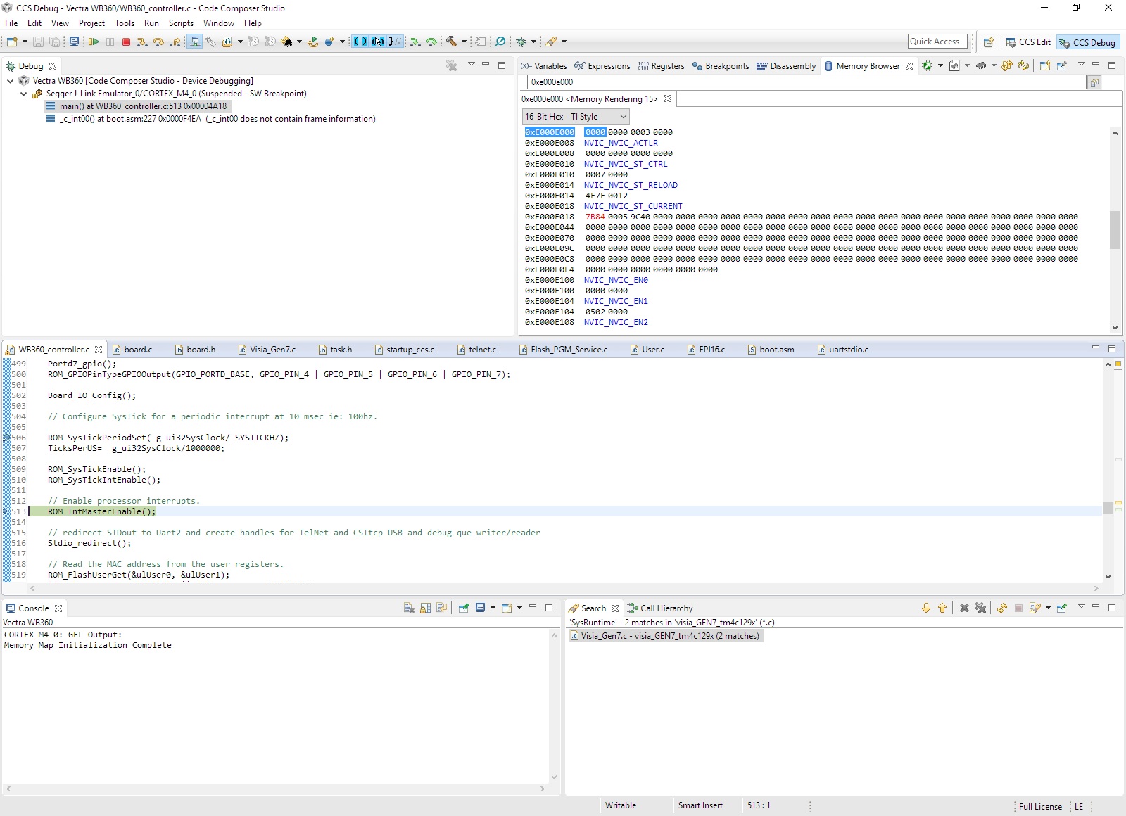
I need to useLwIP. I built my project on a co-worker's exciting project. However, it did not work. The project cannot get IP address, and cannot be found using locator service.  I found another working project. With the same code, the project worked. I discovered that the sysTick was not enabled in the not working project. Stepping through code, I found that the ST_CTRL was cleared after executing ROM_SysTickEnable, and ROM_SYSTickIntEnable. While the same code on the working project does not have this issue. Following is the screen capture of the not working project. Why the ST_CTRL was cleared?

I also tried to change the register in the memory window to enable the timer and the interrupt, however it did not work neither.

thanks

Peng


  • Hello Peng,

    Which exact function stepping causes the SysTick Enable bit to get cleared?
  • BTW, here the ISR table. and the systickhandler. The systickhandler never got executed.

    void (* const g_pfnVectors[])(void) =
    {
    (void (*)(void))((uint32_t)&__STACK_TOP),
    // The initial stack pointer
    ResetISR, // The reset handler
    NmiSR, // The NMI handler
    FaultISR, // The hard fault handler
    IntDefaultHandler, // The MPU fault handler
    IntDefaultHandler, // The bus fault handler
    IntDefaultHandler, // The usage fault handler
    0, // Reserved
    0, // Reserved
    0, // Reserved
    0, // Reserved
    IntDefaultHandler, // SVCall handler
    IntDefaultHandler, // Debug monitor handler
    0, // Reserved
    IntDefaultHandler, // The PendSV handler
    SysTickIntHandler, // The SysTick handler
    IntDefaultHandler, // GPIO Port A
    IntDefaultHandler, // GPIO Port B
    IntDefaultHandler, // GPIO Port C
    IntDefaultHandler, // GPIO Port D
    IntDefaultHandler, // GPIO Port E
    IntDefaultHandler, // UART0 Rx and Tx
    IntDefaultHandler, // UART1 Rx and Tx
    IntDefaultHandler, // SSI0 Rx and Tx
    IntDefaultHandler, // I2C0 Master and Slave
    IntDefaultHandler, // PWM Fault
    IntDefaultHandler, // PWM Generator 0
    IntDefaultHandler, // PWM Generator 1
    IntDefaultHandler, // PWM Generator 2
    IntDefaultHandler, // Quadrature Encoder 0
    IntDefaultHandler, // ADC Sequence 0
    IntDefaultHandler, // ADC Sequence 1
    IntDefaultHandler, // ADC Sequence 2
    IntDefaultHandler, // ADC Sequence 3
    IntDefaultHandler, // Watchdog timer
    IntDefaultHandler, // Timer 0 subtimer A
    IntDefaultHandler, // Timer 0 subtimer B
    IntDefaultHandler, // Timer 1 subtimer A
    IntDefaultHandler, // Timer 1 subtimer B
    IntDefaultHandler, // Timer 2 subtimer A
    IntDefaultHandler, // Timer 2 subtimer B
    IntDefaultHandler, // Analog Comparator 0
    IntDefaultHandler, // Analog Comparator 1
    IntDefaultHandler, // Analog Comparator 2
    IntDefaultHandler, // System Control (PLL, OSC, BO)
    IntDefaultHandler, // FLASH Control
    IntDefaultHandler, // GPIO Port F
    IntDefaultHandler, // GPIO Port G
    IntDefaultHandler, // GPIO Port H
    IntDefaultHandler, // UART2 Rx and Tx
    IntDefaultHandler, // SSI1 Rx and Tx
    IntDefaultHandler, // Timer 3 subtimer A
    IntDefaultHandler, // Timer 3 subtimer B
    IntDefaultHandler, // I2C1 Master and Slave
    IntDefaultHandler, // CAN0
    IntDefaultHandler, // CAN1
    lwIPEthernetIntHandler, // Ethernet
    IntDefaultHandler, // Hibernate
    USB0DeviceIntHandler, // USB0
    IntDefaultHandler, // PWM Generator 3
    IntDefaultHandler, // uDMA Software Transfer
    IntDefaultHandler, // uDMA Error
    IntDefaultHandler, // ADC1 Sequence 0
    IntDefaultHandler, // ADC1 Sequence 1
    IntDefaultHandler, // ADC1 Sequence 2
    IntDefaultHandler, // ADC1 Sequence 3
    IntDefaultHandler, // External Bus Interface 0
    FPGAIntHandler, // GPIO Port J
    IntDefaultHandler, // GPIO Port K
    IntDefaultHandler, // GPIO Port L
    IntDefaultHandler, // SSI2 Rx and Tx
    IntDefaultHandler, // SSI3 Rx and Tx
    IntDefaultHandler, // UART3 Rx and Tx
    IntDefaultHandler, // UART4 Rx and Tx
    IntDefaultHandler, // UART5 Rx and Tx
    IntDefaultHandler, // UART6 Rx and Tx
    IntDefaultHandler, // UART7 Rx and Tx
    IntDefaultHandler, // I2C2 Master and Slave
    IntDefaultHandler, // I2C3 Master and Slave
    IntDefaultHandler, // Timer 4 subtimer A
    IntDefaultHandler, // Timer 4 subtimer B
    IntDefaultHandler, // Timer 5 subtimer A
    IntDefaultHandler, // Timer 5 subtimer B
    IntDefaultHandler, // FPU
    0, // Reserved
    0, // Reserved
    IntDefaultHandler, // I2C4 Master and Slave
    IntDefaultHandler, // I2C5 Master and Slave
    IntDefaultHandler, // GPIO Port M
    IntDefaultHandler, // GPIO Port N
    0, // Reserved
    IntDefaultHandler, // Tamper
    IntDefaultHandler, // GPIO Port P (Summary or P0)
    IntDefaultHandler, // GPIO Port P1
    IntDefaultHandler, // GPIO Port P2
    IntDefaultHandler, // GPIO Port P3
    IntDefaultHandler, // GPIO Port P4
    IntDefaultHandler, // GPIO Port P5
    IntDefaultHandler, // GPIO Port P6
    IntDefaultHandler, // GPIO Port P7
    IntDefaultHandler, // GPIO Port Q (Summary or Q0)
    IntDefaultHandler, // GPIO Port Q1
    IntDefaultHandler, // GPIO Port Q2
    IntDefaultHandler, // GPIO Port Q3
    IntDefaultHandler, // GPIO Port Q4
    IntDefaultHandler, // GPIO Port Q5
    IntDefaultHandler, // GPIO Port Q6
    IntDefaultHandler, // GPIO Port Q7
    IntDefaultHandler, // GPIO Port R
    IntDefaultHandler, // GPIO Port S
    IntDefaultHandler, // SHA/MD5 0
    IntDefaultHandler, // AES 0
    IntDefaultHandler, // DES3DES 0
    IntDefaultHandler, // LCD Controller 0
    IntDefaultHandler, // Timer 6 subtimer A
    IntDefaultHandler, // Timer 6 subtimer B
    IntDefaultHandler, // Timer 7 subtimer A
    IntDefaultHandler, // Timer 7 subtimer B
    IntDefaultHandler, // I2C6 Master and Slave
    IntDefaultHandler, // I2C7 Master and Slave
    IntDefaultHandler, // HIM Scan Matrix Keyboard 0
    IntDefaultHandler, // One Wire 0
    IntDefaultHandler, // HIM PS/2 0
    IntDefaultHandler, // HIM LED Sequencer 0
    IntDefaultHandler, // HIM Consumer IR 0
    IntDefaultHandler, // I2C8 Master and Slave
    IntDefaultHandler, // I2C9 Master and Slave
    IntDefaultHandler // GPIO Port T
    };


    void SysTickIntHandler(void)
    {
    if (!timer_updated)
    ticksSinceUpdate=1;
    else
    ticksSinceUpdate++;
    timer_updated=1; // timer updated by isr

    // Timer for network timing protocol
    SNTP_timerupdate();

    // power on sequence??
    if (SeqTimer){
    --SeqTimer;
    if (!SeqTimer)
    do_seq=1;
    }

    // Call the lwIP timer handler.
    // lwip need a timer to handle 1588
    lwIPTimer(SYSTICKMS);

    //telnet need a timer to handle timeout and TelnetPCB
    telnetTick(SYSTICKMS);

    //User timer. User can add a timer to handle some function. Not needed for scheduler. keep it for now
    UserTimerHandler(SYSTICKMS);
    }
  • Amit,

    It was still in the main function.

    Peng


    On Tuesday, December 6, 2016 10:47 AM, Amit Ashara <bounce-310847@mail.e2e.ti.com> wrote:


    A Message from the TI E2E™ Community
    Texas Instruments
     
    Hello Peng,

    Which exact function stepping causes the SysTick Enable bit to get cleared?
     
     
    You received this notification because you subscribed to the forum.  To unsubscribe from only this thread, go here.
    Flag this post as spam/abuse.


  • Hello Peng

    If the SysTick is not counting then of course it will not go to the interrupt handler. I would suggest that you step through the SysTick functions to see what is causing the SysTick to get disabled in the first place.
  • Amit,

    ROM_SysTickEnable and ROM_SysTickIntEnable are functions in the ROM. Do you know how to step through it? I could not do it.

    I know the counter is counting because the STCURRENT register changes everything when I pause the program

    thanks
    Peng


    On Tuesday, December 6, 2016 11:01 AM, Amit Ashara <bounce-310847@mail.e2e.ti.com> wrote:


    A Message from the TI E2E™ Community
    Texas Instruments
     
    Hello Peng

    If the SysTick is not counting then of course it will not go to the interrupt handler. I would suggest that you step through the SysTick functions to see what is causing the SysTick to get disabled in the first place.
     
     
    You received this notification because you subscribed to the forum.  To unsubscribe from only this thread, go here.
    Flag this post as spam/abuse.


  • I'm not familiar with the CCS yet. But I think it may be something that is project setup related. The same exact code works on the other project. 


    On Tuesday, December 6, 2016 11:05 AM, Peng Peng <ppeng1@yahoo.com> wrote:


    Amit,

    ROM_SysTickEnable and ROM_SysTickIntEnable are functions in the ROM. Do you know how to step through it? I could not do it.

    I know the counter is counting because the STCURRENT register changes everything when I pause the program

    thanks
    Peng


    On Tuesday, December 6, 2016 11:01 AM, Amit Ashara <bounce-310847@mail.e2e.ti.com> wrote:


    A Message from the TI E2E™ Community
    Texas Instruments
     
    Hello Peng

    If the SysTick is not counting then of course it will not go to the interrupt handler. I would suggest that you step through the SysTick functions to see what is causing the SysTick to get disabled in the first place.
     
     
    You received this notification because you subscribed to the forum.  To unsubscribe from only this thread, go here.
    Flag this post as spam/abuse.


  • Amit,

    I found that it is related to the project setup. The processor was not set to the 129ENCPDT. Once I fix this, it register settings are correct now. 

    But it still does not work correctly, the systick isr was not called. So I think it may related to startup_ccs.c. It looks like that the startup_ccs.c was not linked to the project. 

    Can you point me to how to setup the startup_ccs?

    thanks
    Peng


    On Tuesday, December 6, 2016 11:11 AM, Peng Peng <bounce-4540280@mail.e2e.ti.com> wrote:


    A Message from the TI E2E™ Community
    Texas Instruments
     
    Amit,

    ROM_SysTickEnable and ROM_SysTickIntEnable are functions in the ROM. Do you know how to step through it? I could not do it.

    I know the counter is counting because the STCURRENT register changes everything when I pause the program

    thanks
    Peng


    On Tuesday, December 6, 2016 11:01 AM, Amit Ashara <bounce-310847@mail.e2e.ti.com> wrote:


    A Message from the TI E2E™ Community
    Texas Instruments
     
    Hello Peng

    If the SysTick is not counting then of course it will not go to the interrupt handler. I would suggest that you step through the SysTick functions to see what is causing the SysTick to get disabled in the first place.
     
     
    You received this notification because you subscribed to the forum.  To unsubscribe from only this thread, go here.
    Flag this post as spam/abuse.


    You received this notification because you subscribed to the forum.  To unsubscribe from only this thread, go here.
    Flag this post as spam/abuse.


  • Hello Peng,

    I would suggest that you start with project0 in the TivaWare for developing the project files.
  • Thank you Amit. Where can I download the tutorial project?

    Peng


    On Tuesday, December 6, 2016 12:09 PM, Amit Ashara <bounce-310847@mail.e2e.ti.com> wrote:


    A Message from the TI E2E™ Community
    Texas Instruments
     
    Hello Peng,

    I would suggest that you start with project0 in the TivaWare for developing the project files.
     
     
    You received this notification because you subscribed to the forum.  To unsubscribe from only this thread, go here.
    Flag this post as spam/abuse.


  • Hello Peng,

    The examples come as part of the TivaWare 2.1.3 software solution that can be downloaded from TI web page.

    http://www.ti.com/tool/sw-tm4c
  • Hello Peng,

    Did you check if the workspace that you have is corrupted or not?

    A simple method is to create a new workspace, then import the project into the new workspace, compile, load and run the same.

    If renaming a project causes it to stop working, most probable it is a CCS corruption issue (something that has been shown to happen in CCS forum).
  • Amit,

    I tried that many times, it did not work. I started a conversation with TI local support. Here's an email I sent to them, which has more info about this issue. I found a workaround for this. But I don't understand the root cause. Please help us to figure out the root cause.

    thanks
    Peng


    On Thursday, December 8, 2016 9:49 PM, Amit Ashara <bounce-310847@mail.e2e.ti.com> wrote:


    A Message from the TI E2E™ Community
    Texas Instruments
     
    Hello Peng,

    Did you check if the workspace that you have is corrupted or not?

    A simple method is to create a new workspace, then import the project into the new workspace, compile, load and run the same.

    If renaming a project causes it to stop working, most probable it is a CCS corruption issue (something that has been shown to happen in CCS forum).
     
     
    You received this notification because you subscribed to the forum.  To unsubscribe from only this thread, go here.
    Flag this post as spam/abuse.


  • Hello Peng,

    Instead of updating the E2E forum post via your email, please use the response box for replying. I do not see any email/message on the workaround that you have found.
  • Amit,

    Here's the email that I send to local support.

    ___________________________________________________

    Anyway, while I dug into this. I found that the processor went to some wild address 0x0100cdba. Please see attached screen capture.

    I searched the map file. Did not find an address that could be in that location. I kept trying this, later I found that if I enable the internal EEPROM0 using SysCtlPeripheralEnable(SYSCTL_PERIPH_EEPROM0), the project worked fine, no crash at all. I did not find the root cause for this. Since the project is on a tight schedule. I moved forward with this workaround. However, I know that if I don’t understand the root cause, it could come back again.  I need help from Ti to help me find the root cause.

    Attached is the schematics and the CCS project that works. If I comment out line 636 in the WB360.c. The processer crashes.

    ______________________________________________

    uC.pdf

    Thanks

    Peng

  • Hello Peng

    0x0100cdba is the ROM Map region of the uC and is not mapped as the debug symbols in this region are not provided.

    Without enabling the EEPROM, any access to the EEPROM register address space will create a bus fault.

    I also checked the schematics that you have sent
    1. The VDDC pins have 2.2uF while the recommended cap on these pins is 2.5-4.0 uF and we strongly suggest in the system design guidelines application note for 2.2uF+1.0uF+0.1uF cap.
  • Amit,

    thank you for the schematics review. I will updated that. 

    Do you know which ROM function is in that address range? It will be easier to find out the crashing reason with the function address information. I understand that any access to EEPROM register will create a bus fault when the EEPROM is not enabled. That's why I commented out those EEPROM access code. I'll look into if there's any other place access the EEPROM register. 

    Could it be possible that the crash was related to some interrupts? 

    thanks
    Peng


    On Friday, December 9, 2016 1:37 PM, Amit Ashara <bounce-310847@mail.e2e.ti.com> wrote:


    A Message from the TI E2E™ Community
    Texas Instruments
     
    Hello Peng

    0x0100cdba is the ROM Map region of the uC and is not mapped as the debug symbols in this region are not provided.

    Without enabling the EEPROM, any access to the EEPROM register address space will create a bus fault.

    I also checked the schematics that you have sent
    1. The VDDC pins have 2.2uF while the recommended cap on these pins is 2.5-4.0 uF and we strongly suggest in the system design guidelines application note for 2.2uF+1.0uF+0.1uF cap.
     
     
    You received this notification because you subscribed to the forum.  To unsubscribe from only this thread, go here.
    Flag this post as spam/abuse.


  • Hello Peng,

    What is the revision of the TM4C silicon you are using? To be able to get the same information, check the value of the SYSCTL.DID0 register at the address 0x400FE000 and please provide the same.
  • Amit,

    The SYSCTL_DID0 is 0x100A0002.

    Looks like the email system was broken. Here's my reply to your last post.

    thank you

    Peng

    ----------------------------------------------------------------------------

    Amit,
    thank you for the schematics review. I will updated that. 
    Do you know which ROM function is in that address range? It will be easier to find out the crashing reason with the function address information. I understand that any access to EEPROM register will create a bus fault when the EEPROM is not enabled. That's why I commented out those EEPROM access code. I'll look into if there's any other place access the EEPROM register. 
    Could it be possible that the crash was related to some interrupts? 
    thanks
    Peng
  • Hello Peng,

    Thanks for the version info. That helps rule out any errata. As for the interrupts, I cannot say for sure as to how the application code of yours is structured.
  • Amit,

    Are you saying that the 0x0100cdba is for an ISR? Which ISR(0-96) it is?

    thank you
    Peng
  • Hello Peng,

    No, I never said that. In you last post you mentioned that

    Peng Peng said:
    Could it be possible that the crash was related to some interrupts?

    I was referring to the same sentence. To be better able to debug the issue, I would suggest

    1. Please use an EK-TM4C129EXL Crypto connected launchpad to run your application code. See if your code is working?

    2. Please use an existing TivaWare example for Ethernet to see if that works on your board?

    If experiment #1 does works, then please check the layout of your board as your code is OK but something to do with your board

    If experiment #1 does not work, then please send the application code over to us so that we can see if we can reproduce the failure.

    Experiment #2: is to establish the converse of #1.

  • OK. I was following the the previous question of "Do you know which ROM function is in that address range?(0x0100cbda) " .

    Is it possible to find out what function is located at 0x0100cbda. This way, I can figure who called that function, or what caused the function to be called.

    regads
    Peng
  • Hello Peng,

    ROM data is TI proprietary information and cannot be shared. However to isolate the root cause can you please run the experiments listed out in my previous post?