This thread has been locked.

If you have a related question, please click the "Ask a related question" button in the top right corner. The newly created question will be automatically linked to this question.

TM4C1294NCPDT: Setting the PWM Period - Unexpected Results

Other Parts Discussed in Thread: TM4C1294NCPDT, EK-TM4C1294XL

Target

Tiva TM4C1294NCPDT Launchpad (EK-TM4C1294XL)

Note - XTAL (Y1) is 25MHz

Problem

The code below is designed to generate a 25 kHz PWM signal (T=40us) but is observed with a period of 31.1us.

Code & Scope Capture

int main(void) {

	//Clock Init
	SysCtlClockFreqSet((SYSCTL_XTAL_25MHZ | SYSCTL_OSC_MAIN | SYSCTL_USE_OSC), 25000000);	/* 25MHz external XTAL (Y1)				*/


	//******************************************************************************************************************************//
	//	 											    GPIO MODULE INIT															//
	//******************************************************************************************************************************//
	SysCtlPeripheralEnable(SYSCTL_PERIPH_GPIOF);							/* enable GPIO Port F									*/

	GPIOPinConfigure(GPIO_PF2_M0PWM2);										/* set pin-muxes										*/
    GPIOPinConfigure(GPIO_PF3_M0PWM3);

    GPIOPinTypePWM(GPIO_PORTF_BASE, GPIO_PIN_2);							/* set gpio-modules to push-pull output					*/
    GPIOPinTypePWM(GPIO_PORTF_BASE, GPIO_PIN_3);


    //******************************************************************************************************************************//
    //	 											    PWM MODULE INIT																//
    //******************************************************************************************************************************//
	//Init PWM Module
    SysCtlPeripheralEnable(SYSCTL_PERIPH_PWM0);								/* Enable the PWM0 peripheral							*/

    while(!SysCtlPeripheralReady(SYSCTL_PERIPH_PWM0));						/* Wait for the PWM0 module to be ready					*/

    PWMGenConfigure(PWM0_BASE, PWM_GEN_1, 									/* Configure the PWM generator for count down with 		*/
    				PWM_GEN_MODE_DOWN | PWM_GEN_MODE_NO_SYNC);				/* with immediate updates to the parameters 			*/

	//Init PWM0 Gen1
    PWMGenPeriodSet(PWM0_BASE,  PWM_GEN_1, 500);							/* 100% (40us) Tpwm_clk=80ns, 80n*500 = 40us (25kHz)	*/
    PWMPulseWidthSet(PWM0_BASE, PWM_OUT_2, 250);							/* 50%  (20us)											*/
    PWMPulseWidthSet(PWM0_BASE, PWM_OUT_3, 125);							/* 25%  (10us)											*/

	//Start PWM Module
    PWMGenEnable(PWM0_BASE, PWM_GEN_1);										/* Start the timers in Generator Module 1				*/

    PWMOutputState(PWM0_BASE, (PWM_OUT_2_BIT | PWM_OUT_3_BIT), true);		/* Enable the outputs									*/


    //spin
	for(;;) {
		_nop();
	}
}

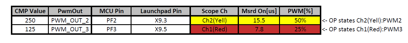
See below for measured results, Ch1(Red): PWM3, Ch2(Yellow): PWM2 -


Question

Why do I see a period of 31us, not 40us?


Calculations Used


Fclk = 25MHz, Fclk_pwm = 12.5 MHz

Tclk_pwm = 80ns

N_per_pwm = 500

T_per_pwm = 40us (but 31.1us observed?)

  • Have you noted not only frequency error - but if your scope cap is to be believed - PWM2 (red) is half the duty cycle of PWM3(yel).   (You've likely transposed - code shows the opposite!)

    I can't spot any code error - and you've done a nice job in detailing your calculations. (Bravo that)

    Might your System Clock be off? You can cause a low impedance and accurate replica of the System Clock to be output upon a Timer pin. I'd be suspicious of your xtal, xtal caps, xtal routing. (assumes homebuilt pcb - untrue for vendor board)

  • Probably could have displayed this with more clarity :) -

    Original:  "Ch1(Red): PWM3, Ch2(Yellow): PWM2"

    Cleaner:

    • Ch1 (Red) = PWM3
    • Ch2 (Yellow) = PWM2

    Correction:  "PWM2 (red) is half the duty cycle of PWM3(yel)."

    • PWM2 is yellow, you misread. My apologies!

    Here is a cleaner table:


    Also importantly to note, I am using the 1294's Launchpad (EK-TM4C1294XL), so this is observed on a factory board! :)


    Assumptions:

    • The HW is all correct and functional (it is a TI Launchpad)
    • My measurements are correct (PWM2_ON= 50%, PWM3_ON=25%)

    Question:

    • What is wrong then?

  • Do you know your 'scope is correct?

    Robert
  • Hello Justin

    First monitor the System Clock output on the SYSCLKOUT pin with a known divider to check if the system clock is as expected.
  • Oh Robert - a (scope) NOT being correct!
    Do note that (always) dreaded "void" has NOT been reported.

    And Amit - while firm/I don't know/use x129 - we suggested similar output mechanism to reveal Sys. Clk. We (prefer) "our" method as it avoids the (special, thus LIMITED) method present in x129 - but NOT in far more popular x123! (power to the people (or basic MCUs))
  • Your latest presentation IS substantially improved. (yet I (stand) by my initial comment - PWM scope outputs are "flipped" from your 1st code listing)

    Note that vendor's x129 REQUIRES an entirely changed function call - to set up System Clock. (that's always lovely - further confuse an (already) confused user base!)

    Might you have "missed" that - and employed code for the x123? (same as for our LX4F) Such would explain your "frequency" plight.

    You're clearly smart/detailed enough to solve - presentation of your "System Clock" set-up commands and any/all intrusions of Sys Clk into "PWM frequency set" will enable this "crack crue" of outsiders (and of course the "boss" Amit) to quickly/fully resolve...

    Again note that this reporter was very FIRST to suggest outputting Sys Clk (or divided replica) as best means to confirm frequency!    (Green Post Award - just slightly/barely - hereby solicited!    Xmas coming - hungry mouths abound - coal stuffed in stockings (rather than burned) less than desirable thanks to failed, illegal server hosting, (past) candidate...)

  • cb1_mobile said:
    Oh Robert - a (scope) NOT being correct!
    Do note that (always) dreaded "void" has NOT been reported.

    True enough, and it's rare that an oscilloscope would be off, rarer still that much. Still if the SW must be correct then the measurement technique should be verified.verifying the operating frequency as pointed out is an obvious step.

    Robert