This thread has been locked.

If you have a related question, please click the "Ask a related question" button in the top right corner. The newly created question will be automatically linked to this question.

EK-TM4C123GXL: How many pins are available?

Part Number: EK-TM4C123GXL

Hello!

I will be handling multi-pin input. Apparently – packs of 8-20 bits pushed together at each clock. I attach the possible formats of input:

http://imgur.com/a/6yeYx

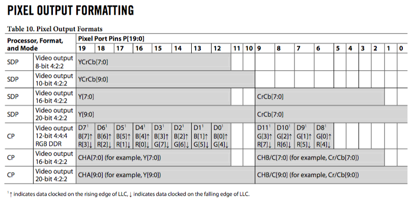
I'll bee needing 8 pins to drive a LED matrix. Which pixel-data input formats will I be able to support? 8-bit? 12, 16 or 20 bit? I think I can hit pin number limit with 20-pins.

Best regards,

Sebastian

  • Hello Sebastian

    What is the application that you are looking for?
  • I just wanted to ask about pins from practical point of view. Because there can be e.g. 30 pins, but only 15 of them to be used as digital inputs. Things like that – input-only pins, output-only pins, analog-only pins, etc. Here I state that I will be needing 8 output pins (rather digital but unsure yet) and 8-20 digital input pins – and politely ask if Tiva C will be able to handle this? 8-output + max 20-digital-input pins.

    The application is: video decoder chip to decode analog PAL/NTSC signal – into digital 8 to 20 bit pixel data – to be read by Tivia, scaled and written to RGB LED matrix.

    BTW, could I use Tiva C to read double data rate DDR input? The "CP" processor in the attached table.

    Best regards,
    Sebastian
  • Hello Sebastian,

    On TM4C devices, every IO can be configured as Input Only or In output only mode. So with the total IO's available on the header you should be able to get the 28 pins. However, now when you mention it is to decode PAL/NTSC analog signal to digital 8-20 bit pixel data, we are entering the domain of video processing which is way specialized. Also DDR at what rate?
  • The chip is ADV7181C :

    www.digchip.com/.../ADV7181C-pdf.php

    I searched for "MHz" in the document but didn't find any data. I only found that there is 28.63636 MHz crystal. I hope for help. Yeah this can be perceived as video processing, with question stated: will Tiva C handle YCbCr video input?

    Best regards,
    Sebastian Gniazdowski
  • Hello Sebastian

    The video output output is 110MHz as per the document I could see and that would not be possible by TM4C devices.
  • Thank you! A devastating news though. Do you maybe refer only to DDR mode? Will plain 8-bit YCbCr 4:2:2 mode be possible? Maybe lowering something is possible, like frames per second? I really like Tiva C and MSP430, chosen the ARM Cortex MCU being sure I will have enough processing power.. All I need is e.g. 10 FPS, scaled down to 16x32, outputted to RGB LED matrix.

    Best regards,
    Sebastian
  • There are Arduino cameras, like OV7670: www.arducam.com/.../

    They also output YCbCr 4:2:2, in resolution similar to PAL/NTSC (all data in the link). Arduino can read that – why ARM Cortex MCU (Tiva C) wouldn't read similar data from video decoder?

    Best regards,
    Sebastian Gniazdowski
  • Hello Sebastian,

    Since I cannot wrap my head around the application, will something like the following reference design be a better match for what you are trying to do?

    www.ti.com/.../TIDM-TM4C129CAMERA
  • Thanks for the reference design. 123GXL is easily available in Poland in Farnell, not that luck with TM4C129CAMERA. I need to scale PAL/NTSC input to 32x16 for output to 16x32 LED matrix, so LCD driver isn't needed. I researched that by 110MHz you mean LLC pin. Each clock tick on that pin is 1 pixel on P0-P19. The LLC has range from 12.825MHz to 110MHz. For lower resolution like PAL and NTSC, I could count on luck that the frequency will be lower than 80 MHz of the ARM Cortex. Meaning Tiva C could handle the input? Say 60 MHz LLC.

    I would do online scaling to 32x16. Read 18 pixels, decimate to 1. Read 45 lines, decimate to 1. This will fit into 32 kB of memory of Tiva C (max memory usage: 45 x 32 = 1.44 kB, when 45 decimated lines await for decimation), and I could then drive the LED matrix.

    Best regards,
    Sebastian
  • Hello Sebastian

    As I mentioned earlier, I would go for the worst case scenario on the datasheet of the co-processor. In this case after scaling, it would be a tough match for the TM4C123x device. Bit banging and low level control could help but in the absence of a wide bus like EPI, it is going to be a no-show for the TM4C123x device unless the scaling is way too low. Again, it is your decision based on what is acceptable.
  • Thanks! Discussing helped me much, I now see why this is impossible – except for one tip of a person who thinks that uDMA could read one byte-by-byte on GPIO pin trigger – but too poor data to engage in this.
  • Hello Sebastian,

    Yes. It would be more limiting your application to getting some data, rather than getting a better feature set.