This thread has been locked.

If you have a related question, please click the "Ask a related question" button in the top right corner. The newly created question will be automatically linked to this question.

TMS470MF06607: HET pwm line not getting LOW when duty cycle is changed from 100 to 0

Part Number: TMS470MF06607
Other Parts Discussed in Thread: HALCOGEN

Hello TI,

Development boardTMDX470MF066HDK Hercules Development Kit


I am using HET to generate a PWM signal. The driver level code of HET is generated from HALCoGen.
My application demands the PWM pin to be LOW when needed. I am just changing duty cycle to 0 % for the same.
When i change duty cycle from 100 % to 0 %, the HET pin still persists to be HIGH. However any changes from 1-99 % duty cycle to 0% is working absolutely fine, the HET pin becomes LOW.

The issue gets resolved with the following work-arounds, but I still don't understand what's going wrong!


Workaround 1:  When I put a delay after PwmSetDuty(0), the pin becomes LOW(0 % duty cycle) from HIGH(100 % duty cycle)

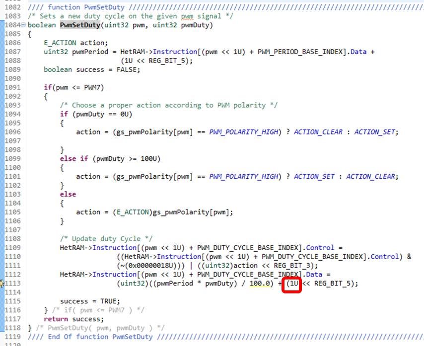
Workaround 2:  This is how my PwmSetDuty Function looks like:-

When I increment the count of DATA field in PWCNT instruction by 1, that is replacing 1U (marked red in image) with 2U.
However this will intoduce inaccuracy in the generated pulses, which is undesirable.

The HET pin becomes LOW(0 % duty cycle) from HIGH(100 % duty cycle) after this work-around.

Please help me in finding the cause of issue and resolving the same.


If I have created any confusion please get back to me.

Thanks in advace!

  • Hello Sanjeev,

    Thanks for using the E2E. Unfortunately, the issue that you have mentioned is a weakness in the HET program that is generated by Halcogen. The issue gets back to the use of the PWCNT instruction and the inability of the instruction to handle two condition changes at once. If you have a look at the psuedo code in the TRM for this instruction you will see there is a relatively complex set of conditional statements that are considered and if one is satisfied the remainder don't get checked. In this case, the end of the pulse is detected but not the change in duty cycle. The only way to solve this issue is to use different instructions and re-design the HET program from the ground up. From my understanding, trying to eliminate corner cases such as this limitation, can be very challenging and increase the complexity of the program dramatically.

    Can you provide further details on your workaround #1? Is this simply putting a delay after each call to the PwmSetDuty call? Are there any negative affects that this has on your application? I'm not certain of the reason that this works. Perhaps because it allows one more LRP after the end of the pulse? I would need to review your solution with one of our HET experts to determine the explanation why this might help.

    Also, I would agree that workaround #2 is not realistic if it adds inaccuracy into your PWM pulse widths that are significant enough to impact your application. The reason this is effective, however, is due to the fact that it prevents the duty cycle from ever truly reaching 0.

    As an FYI, we do have an Application Note on the PWM from Halcogen that might be useful to you in understanding the Halcogen HET program. The app note is located at this link: www.ti.com/.../spna225.pdf. Although it doesn't explicitly discuss this specific issue, it does also list several other limitations that might be of interest. Also, there is a listing of the HET program included in the appendix of the document.
  • Thanks Chuck for your quick n elaborate reply!

    Here are further details :-

    Is this simply putting a delay after each call to the PwmSetDuty call?

    * For workaround#1, I am not putting delay after each call to PwmSetDuty(), there is a delay required only after setting 0% duty cycle, that too specifically when we need to change duty cycle from 100% to 0%

    Are there any negative affects that this has on your application?

    For now there is no significant effect, but as the application evolves, the workaround#1 may be a problem to be dealt with. And yes the delay I am providing is more than 1 loop resolution period.
    I am still not satisfied with the justification on the cause of workaround#1 resolving the issue.

    Also I din't got the following point you made for workaround#2

    "The reason this is effective, however, is due to the fact that it prevents the duty cycle from ever truly reaching 0"

    Thanks for the HET app note link. I will go through it. :)

  • Sanjeev,

    So the limitation that you see as the 100%->0% duty cycle boundary condition is simply a result of the instructions with which the PWM is implemented.

    It's four instructions that implement a double-buffered period & duty cycle :

    DPWM_1 PWCNT { next=PPWM_1, hr_lr=LOW, cond_addr=PPWM_1, pin=PIN_PWM1, action=POL_PWM1,reg=NONE, irq=OFF, data=DUTY_CNT1, hr_data=0};
    PPWM_1 DJZ { next=DPWM_2, cond_addr=DLOAD_1, reg=NONE, irq=OFF, data=PERD_CNT1};
    ...
    ...
    DLOAD_1 MOV64 { next=PLOAD_1, remote=DPWM_1,en_pin_action=ENABLE_PWM1,cond_addr=PPWM_1, pin=PIN_PWM1, comp_mode=ECMP, action=POL_PWM1, reg=NONE, irq=EOD_IRQ1, data=DUTY_LOAD1};
    PLOAD_1 MOV64 { next=DPWM_2, remote=PPWM_1, cond_addr=DLOAD_1, comp_mode=ECMP, reg=NONE, irq=EOP_IRQ1, data=PERD_LOAD1};
    
    Now look at the psuedo-code for PWCNT (In the TRM section 12.7.3.16 PWCNT (Pulse Width Count))

     If (Data field value == 0)
    {
    Selected register = 0;
    Jump to Next Program Address;
    }
    If (Data field value > 1)
    {
    Selected register = Data field value - 1;
    Data field value = Counter value - 1;
    If (Enable Pin action == 1)
    Selected Pin = Pin Action AT next loop resolution clock;
    Jump to Next Program Address;
    }
    If (Data field value == 1)
    {
    Selected register = 00000h;
    Data field value = 00000h;
    If (Opposite action == 1)
    {
    If (hr_lr bit == 0)
    {
    If (Enable Pin action == 1)
    Selected Pin = Opposite level of Pin Action AT next loop 
    resolution clock + HR delay;
    }
    else
    {
    If (Enable Pin action == 1)
    Selected Pin = Opposite level of Pin Action AT next loop 
    resolution clock;
    }
    }
    If (Interrupt Enable == 1)
    SW interrupt flag = 1;
    Jump to Conditional Address
    }

    I will paraphrase the above as:

     Data Field == 0

          ... do nothing

     Data Field == 1

         ...  schedule pin to flip to 'opposite' state at next LRP,  decrement count.

     Data Field > 1

         ...  schedule pin to be in active state at next LRP, decrement count

    The problem is this:

      - to get a 100% duty cycle, especially over multiple periods,  we need to program the PWCNT data field in DPWM_1 with a value larger than what is in PPWM_1 so that the PWCNT in DPWM_1 never executes with a '1' in the data field.   If it were to execute with a '1' in the data field,  then the pin would go to the opposite pin state for at least 1 loop resolution period, and you would never get a 100% duty cycle with the pin 'on' 100% it would always have a small off time of one loop.

      - if the PWCNT is setup for 100%,  and the next period is 0% what happens is:

          - PWCNT executes with a data field of '2' .. this keeps the pin set 'on' but then leaves the value '1' in the PWCNT data field.

           left alone, the next iteration of PWCNT would return the pin to the OFF state.

          - In the same loop that the PWCNT goes from 2->1,  the DJZ is zero and this causes the program to jump to address DLOAD_1 where DLOAD_1

            and PLOAD_1 are executed.    DLOAD_1 writes a value of '0' into PWCNT before PWCNT has a chance to execute with a value of '1'.


    So now during the 0% duty cycle the PWCNT immediately has a value of 0 and always 'does nothing' to the pin.

    But because the prior period left the pin "ON" the pin stays on and therefore it appears stuck or hung.


    To correct the problem you have to rewrite the code.   I tried one experiment with ADCNST replacing MOV64 and was able to get the PWCNT to transition from 100% to 0% to 100% without issue but don't know for certain that the values in between are good.    Usually with HET a simple change like this might introduce another boundary condition somewhere else.    


    So just to explain, instead of doing a "MOV64" which writes over the '1' with a '0',  adding a '0' to whatever is left in the PWCNT is a better strategy to get 0% because:

        a) if there is already a '0' in PWCNT, this means the pin is already turned off  (previous duty cycle was not 100%).

        b) if there is a value of '1' in PWCNT, this means that the last duty cycle was 100% but adding 0 to it leaves the PWCNT with a value of 1.

           so it will execute with a value of 1 -> 0 and turn the pin OFF in the next loop resolution period.

       c) the way that ADCNST works, it either adds the immediate value to the remote value (if the remote is not zero) or it adds an offset to the immediate value

           and writes this to the remote (if the remote is 0).  

           So you can set immediate = duty - 1 and then have an offset = 1.

           If the remote value is '1' from a prior run with 100% duty,  ADCNST will add   duty -1  to 1 and leave you with 'duty' in the PWCNT field.

           If there remote value is '0' from a prior < 100% duty,  ADCNST will add duty -1 +  1 (Const offset field of ADCNST) and you still get 'duty' in the PWCNT.

    There are some problems with using ADCNST though.   First, it doesn't do a Control field update like MOV64 does.   So you cannot 'buffer' the polarity or the enable or any of the other fields and synchronously update them at the end of a period with just ADCNST like you can with MOV64.   So some of the APIs that depend on these fields being updated in the 'buffer' location of the MOV64 (PLOAD_1, DLOAD_1) will break.

    Then, by having an "ADD" instead of a 'MOV" you will have the chance that some error accumulates in the remote PWCNT register; especially if the period in the DJZ instruction is changed at the same time duty cycles are changed.  
    If you ever leave PWCNT with a value of '2' for example, instead of '1' .. then the ADCNST with an offset of '1' is wrong and will break,  and if this then turns into a case next where a '3' is left in PWCNT this error can snowball.    Whereas MOV64 writes a defined value to the PWCNT without 'adding' so errors cannot snowball.


    I don't know if the second issue is real or not but I would want to thoroughly simulate this before changing the HET code.  My own experience and that of colleagues has been that these boundary conditions like 100% -> 0% are easier to 'move' than to actually get rid of.   What I mean is that it's more likely that fixing a 100% -> 0% boundary condition will just move the problem to the 0% -> 100% case, or that it will introduce a slight error in PWM duty under certain cases, rather than making the PWM 'perfect'.   To make it 'perfect' usually means adding instructions to handle the corner cases.