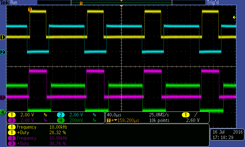
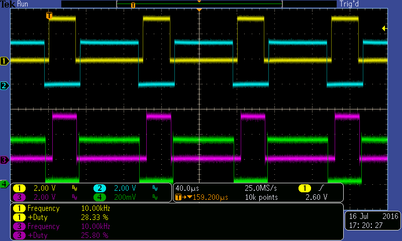
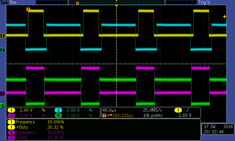
I have an issue where a PWM pulse of varying duration appears before the proper PWM starts. PWMs are on pins PD0 and PD1. I use the eval board buttons to start and stop the PWM. The first time I boot I roughly get the duration of the green pulse. If I stop then start the PWM again the PWM at the start is of different shape and could be the yellow or green trace. I think this is due to the PWM counter being non zero at the start but not sure.
The start of the PWM should be the yellow trace but the green trace appears prior. Code is:
//To make complimentary PWMs using deadband


//Includes
#include "inc/tm4c123gh6pm.h"
#include <stdint.h>
#include <stdbool.h>
#include <stdlib.h>
#include <string.h>
#include <ctype.h>
#include "inc/hw_memmap.h"
#include "inc/hw_types.h"
//#include "inc/hw_ints.h"
#include "driverlib/sysctl.h"
#include "driverlib/adc.h"
#include "driverlib/gpio.h"
#include "driverlib/debug.h"
#include "driverlib/interrupt.h"
#include "driverlib/pwm.h"
#include "driverlib/timer.h" //just added in v3
#include "driverlib/pin_map.h"
#include "driverlib/uart.h"
#include "inc/hw_gpio.h"
#include "utils/ustdlib.h"
//#include "C:/ti/TivaWare_C_Series-2.1.0.12573/utils/ustdlib.h"
//#include "utils/uartstdio.h"
//#include "utils/cmdline.h"
#include "driverlib/rom.h"

void InitPWMs(void);


//Frequency stuff
unsigned int ui32PWMFreq = 126000;//Default boot frquency

void InitPWMs(void)
{
	uint32_t ui32LoadIn;
	uint32_t ui32PWMDeadband;

	//Setup for bridge drive with 2 PWMs on M1PWM0 PD0, M1PWM1 PD1
	ROM_SysCtlPeripheralEnable(SYSCTL_PERIPH_PWM1);//changed from PWM1
	ROM_SysCtlPeripheralEnable(SYSCTL_PERIPH_GPIOD);//for M1PWM0 M1PWM1 and UART2

	//Configure PWM0 on module 1 which is pin PD0 and PWM1 on mondule 1 on pin PD1
	ROM_GPIOPinTypePWM(GPIO_PORTD_BASE, GPIO_PIN_0);//Sets PD0 to PWM
	ROM_GPIOPinTypePWM(GPIO_PORTD_BASE, GPIO_PIN_1);//Sets PD1 to PWM
	ROM_GPIOPinConfigure(GPIO_PD0_M1PWM0);//Module 1 PWM0
	ROM_GPIOPinConfigure(GPIO_PD1_M1PWM1);//Module 1 PWM1


	//Setup clock and frequency
	ui32LoadIn = (ROM_SysCtlClockGet() / ui32PWMFreq);//Determine count to put in timer reg (already has -1 in PWMGenPeriodSet
	ui32PWMDeadband = ui32LoadIn*5/100;//deadband count

	//Setup PWM1
	ROM_PWMGenConfigure(PWM1_BASE, PWM_GEN_0, PWM_GEN_MODE_DOWN | PWM_GEN_MODE_DBG_RUN |PWM_GEN_MODE_GEN_SYNC_LOCAL | PWM_GEN_MODE_DB_SYNC_LOCAL);


	//Set PWM period and Duty Cycle
	ROM_PWMGenPeriodSet(PWM1_BASE, PWM_GEN_0, ui32LoadIn);//Load value into PWM should be 16 bit and already has -1 in funciton
	ROM_PWMPulseWidthSet(PWM1_BASE, PWM_OUT_0, ui32LoadIn/2);//Sets PWM Pulse Width (DutyCycle)

	//setup out output enable config for local update
	//HWREG(0x40029000+0x028)=0b1010;

	//Setup deadband
	ROM_PWMDeadBandEnable(PWM1_BASE,PWM_GEN_0,ui32PWMDeadband>>1,ui32PWMDeadband>>1);//Configure deadband on PWM1 PMW0


}//End of InitPWM1


//Start of main----------------------------------------------------------------------
int main(void)
{


	//40MHz clock, use ROM command to save space!
	ROM_SysCtlClockSet(SYSCTL_SYSDIV_5|SYSCTL_USE_PLL|SYSCTL_OSC_MAIN|SYSCTL_XTAL_16MHZ);
	ROM_SysCtlPWMClockSet(SYSCTL_PWMDIV_1);//Sets PWM, set to 40MHz?

	ROM_SysCtlPeripheralEnable(SYSCTL_PERIPH_GPIOF);//Enable clock on peripheral for LEDS
	//wait for GPIOF module to be ready
	while(!SysCtlPeripheralReady(SYSCTL_PERIPH_GPIOF))
	{
	}

	//Config LEDS
	ROM_GPIOPinTypeGPIOOutput(GPIO_PORTF_BASE, GPIO_PIN_1|GPIO_PIN_2|GPIO_PIN_3);//Set PF1,2,3 to output type APB which can toggle every two cycles

	//Turn LED REd on
	GPIOPinWrite(GPIO_PORTF_BASE, GPIO_PIN_1, 2);//Turn Red LED on

	//Sets up buttons SW1 and SW2 I think...
	HWREG(GPIO_PORTF_BASE + GPIO_O_LOCK) = GPIO_LOCK_KEY;
	HWREG(GPIO_PORTF_BASE + GPIO_O_CR) |= 0x01;
	HWREG(GPIO_PORTF_BASE + GPIO_O_LOCK) = 0;
	ROM_GPIODirModeSet(GPIO_PORTF_BASE, GPIO_PIN_4|GPIO_PIN_0, GPIO_DIR_MODE_IN);
	ROM_GPIOPadConfigSet(GPIO_PORTF_BASE, GPIO_PIN_4|GPIO_PIN_0, GPIO_STRENGTH_2MA, GPIO_PIN_TYPE_STD_WPU);

	//Enable PWM Module 1 PWM0,PWM1 here
	InitPWMs();


	while(1)
	{
		//Turns On PWM
		if((ROM_GPIOPinRead(GPIO_PORTF_BASE,GPIO_PIN_4)==0x00))
		{
			//Turn on PWM
			ROM_SysCtlDelay(5000000);//Blocks X seconds?
			//Turn PWM10 ON
			ROM_PWMOutputState(PWM1_BASE, PWM_OUT_0_BIT | PWM_OUT_1_BIT , true);//PWM0 set to output
			//HWREG(0x40029054)=0x0000;
			ROM_PWMGenEnable(PWM1_BASE, PWM_GEN_0);//Runs PWM


		}//End of switch1 Turns on PWM

		//Turns off  PWMs
		if((ROM_GPIOPinRead(GPIO_PORTF_BASE,GPIO_PIN_0)==0x00))
		{
			//Turn off PWM
			ROM_SysCtlDelay(5000000);//Blocks X seconds?
			ROM_PWMOutputState(PWM1_BASE, PWM_OUT_0_BIT | PWM_OUT_1_BIT, false);//PWM0 set to output off
			ROM_PWMGenDisable(PWM1_BASE, PWM_GEN_0);//turns off PWM
			//Sets PD0 low since seems to off can be high...

			//Setoutputs low

		}//End of switch 2 turn off PWM


	}//end of main while loop
}//******************end of main************************


