This thread has been locked.

If you have a related question, please click the "Ask a related question" button in the top right corner. The newly created question will be automatically linked to this question.

RTOS/TM4C1294NCPDT: Firmware upgrade

Part Number: TM4C1294NCPDT

Tool/software: TI-RTOS

Hello :)

I would like to update the Firmware by uploading a bin file on a website as seen on Wifi Routers.

I made lightweight boot loader just providing a webpage,  and receiving the new firmware. This Firmware is flashed then in a Flash region below my bootloader. The bootloader it self will never be touched. 
To flash the tiva I used the Driverlib Librarys and FlashProgram(uint32_t *pui32Data, uint32_t ui32Address,uint32_t ui32Count);

The question now:
I can choose many .hex file formats in code generation for my target firmware image. Is there a format I just can flash with "FlashProgramm" byte by byte without further interpretation?

Thanks for your answers :)
Cheers,

Chris

  • Hi Chris,

    Past experience with flash utility used in boot loader requires a (*.bin) format uploaded as 256Kb pages. Target uses FTP to Get bin file from a local host. So it would seem the targets http web page must have FTP server code to control binary file transfer started with targets broadcast of a BootP request, local network only. Broadcasts from layer 3 network devices stop at the router being layer 2 devices.

    Hope this helps Get some ideas flowing.
  • Hi, thanks for your answer.

    I don't want to use a flash utility, I thought to transmit the .bin file with file upload over HTML. This is much more comfortable for the users.

    It is much done already, I "just" need to know now which .hex format I have to choose (like TI-TXT) of my target firmware (not the bootloader) to directly program the flash by the functions provided in flash.c. Or do I missed something?
  • Seems to me flash.c requires a binary file to write the target. So you must ftp(get \*.bin) file by adding a remote host (print/file share) named in your code for the ftp (get file C drive) with (Webusers/read access). Text files are ASCII or other formats and not binary hex data.
  • Hello Chris

    Irrespective of the method, the data to be sent to the MCU must have a format where there is a start address provided along with the number of bytes. This should be then followed by the data bytes to program. A binary file format effectively achieves the same. If you use a HEX or any other format that is deviant from bin file format, then necessary conversion needs to be performed before the file is sent over the network.
  • Dear Amit, thanks for your answer.

    I don't get this. I already received the data on the tivaC, I am using my own bootloader. There is no point on how the data is formatted on the delivery - the question is on how I have to prepare these data, that they can be executed later on tiva.

    Today I implemented the software as followed:

    1. Receive the hex file from the user via http upload.

    2. store the .hex file, or a part of it, in the SRAM of the TivaC

    3. remove meta data added from the browser

    4. precondition the data <--- Question

    5. use flashprogramm() (Driverlib, flash.c) to program into the tivaC Flash

    6. jump to the flashed image and execute the new program

    I generate my target firmware also in CCS. Therefor I use the .hex generator from CCS. What format the .hex should have (like intel format) that it can be executed after storing in the tiva Flash? 

    Thanks for your answers and sorry for the confusion.

  • Hi,

    See this link for info about .hex file format.

    After downloading to RAM, you need to revert to binary form and that is to be saved to flash. This is because the .hex file format replaces each binary byte by two ASCII characters, corresponding to each nibble of a byte.

  • Thanks for your answer. Thats the question, can you recommend me a .hex format what does not need much post processing? I think the intel format is the most complex of the available. Is there any sequence in the beginning of each firmware so I could test if I decode the thing the right way?
  • Hi,

    You have all you need to test/check the software: the .hex file generated by CCS - open it with a text editor since is all ASCII chars, compare with info in the link provided and find out what TI uses to make .hex file.

    You can generate also .bin file to check with yours. As for yours, write it for yourself, it is not difficult to do it if you have understand the link info. Use the PC to make such program and test the functions you write. Do it with ARM in mind.

    Also the simplest work is to use .bin file, no auxiliary processing needed.

  • Hi, thanks for your reply.

    You are right, I am using the .bin file directly now. There is no need to generate the hex at all.
    There is another problem now, my bootloader is not jumping to the right entry point of the target application.

    My Bootloader is a TI-RTOS application, the target firmware is a simple blinky program out from the Tiva examples.

    The behavior is very special:

    The blinky application is loaded into the flash from 0x30000 succesfully.
    The blinky firmware is not running when I jump with the following code from the bootloader:

        //
        // Set the vector table to the beginning of the app in flash.
        //
        HWREG(NVIC_VTABLE) = ui32StartAddr; //0x30000
    
        //
        // Load the stack pointer from the application's vector table.
        //
        __asm("    ldr     r1, [r0]\n"
                "    mov     sp, r1\n");
    
        //
        // Load the initial PC from the application's vector table and branch to
        // the application's entry point.
        //
        __asm("    ldr     r0, [r0, #4]\n"
                "    bx      r0\n");

    The blinky it self is running in CCS without problems, and is starting from the flash at 0x30000. So I could figure out the entry point address by debugging the blinky application, it is 0x000304A8.
    The funny thing is, that I can manually trigger the tiva to run my blinky application. Therefore I debug my bootloader application and set the PC register manually to 0x000304A8 before any other code is running.

    It seams to my that the entry point address is not compiled into the blinky binary correctly. Is there anything else I have to change in the blinky app apart of the base address in the linker?

    The blinky applications linker file:

    #define APP_BASE 0x00030000
    #define RAM_BASE 0x20000000
    
    MEMORY
    {
        FLASH (RX) : origin = APP_BASE, length = 0x000E0000
        SRAM (RWX) : origin = 0x20000000, length = 0x00040000
    }
    SECTIONS
    {
        .intvecs:   > APP_BASE
        .text   :   > FLASH
        .const  :   > FLASH
        .cinit  :   > FLASH
        .pinit  :   > FLASH
        .init_array : > FLASH
    
        .vtable :   > RAM_BASE
        .data   :   > SRAM
        .bss    :   > SRAM
        .sysmem :   > SRAM
        .stack  :   > SRAM
    }
    
    __STACK_TOP = __stack + 512;


    Thanks for any help!

  • Hi,

    Suggest to see the file Tiva/boot_loader/bl_startup_ccs.s and from CallApplication function to compare with your code. The snippet provided is a little bit unclear since it is not shown what are the registers content after previous HWREG code line.

    Test first an boot loader application provided by TI. 

  • Chris,
    In case this is of any help:
    - We also use the "plain" .bin format created by CCS.
    - The updated firmware is stored in an area of flash (or external RAM if you prefer). And we mark a few eeprom flags that will be used by the bootloader on the next boot.
    - The bootloader sees the flags which indicate "new firmware available", and swaps the old FW by the new one.
    - There are some additional tricks, i.e. make sure only a firmware "built for this particular board" is accepted - and there is a watchdog that requires to be reset by the new firmware within some time - otherwise, old firmware is automatically restored (so that you don't risk bricking the device).
    Regards
    Bruno
  • Hi, thanks for your replies.

    to clarify, I use the words "boot loader" for my little TI-RTOS application providing a web-server for .bin file upload and for starting a target application somewhere in the flash.
    I use target application for my target application, in this case a simple blinky, later a TI-RTOS application.

    @Bruno: I had similar thoughts. I very like your idea to use the watchdog to determine if the new firmware is running. Thanks for sharing!

    This is how I thought to proceed:
    - My boot loader is testing the checksum of the target application stored somewhere in the flash.
    - If this test is successful it starts this application.
    - else it hangs in the boot loader until the user is uploading a new target firmware.

    So, in worst case the user has to upload a new firmware, he can not brick the device - so far.


    I am using the post of Amit, 2014 as a template. On these files from the link: The startup_css.c from the boot loader as well as the application (Strap Code) seams to me original (apart of the application address).

    Is there a command to directly set the PC to a new address? Because as I said, the firmware is running If I debug my boot loader application in CCS and set the PC to the entry point of my target application.

    How can I debug this Issue? So far I can only guarantee that the target application is in the flash completely.

    Any idea how to proceed, what can I post for clarification?

    Regards

    Chris 

  • Chris,
    In our case, the transfer of the update bin happens within the main application, not within the bootloader.
    We just add a .h file with the necessary functions, and the new bin can arrive "via any physical connection - uart, eth, etc." during product "normal use".
    Our custom bootloader is really small and does not handle transfers - it just manages swapping code blocks when the proper flags are set.
    Again, might be too specific for our case - but it is a suggestion.
    Bruno
  • Hi Bruno

    Thanks for the clarification :).  I am using the main application because I need web server functionality. I do not have to care about swapping code with this method. Furthermore It is very unlikely to brick the device. Off course I need a lot of memory for this startup application.

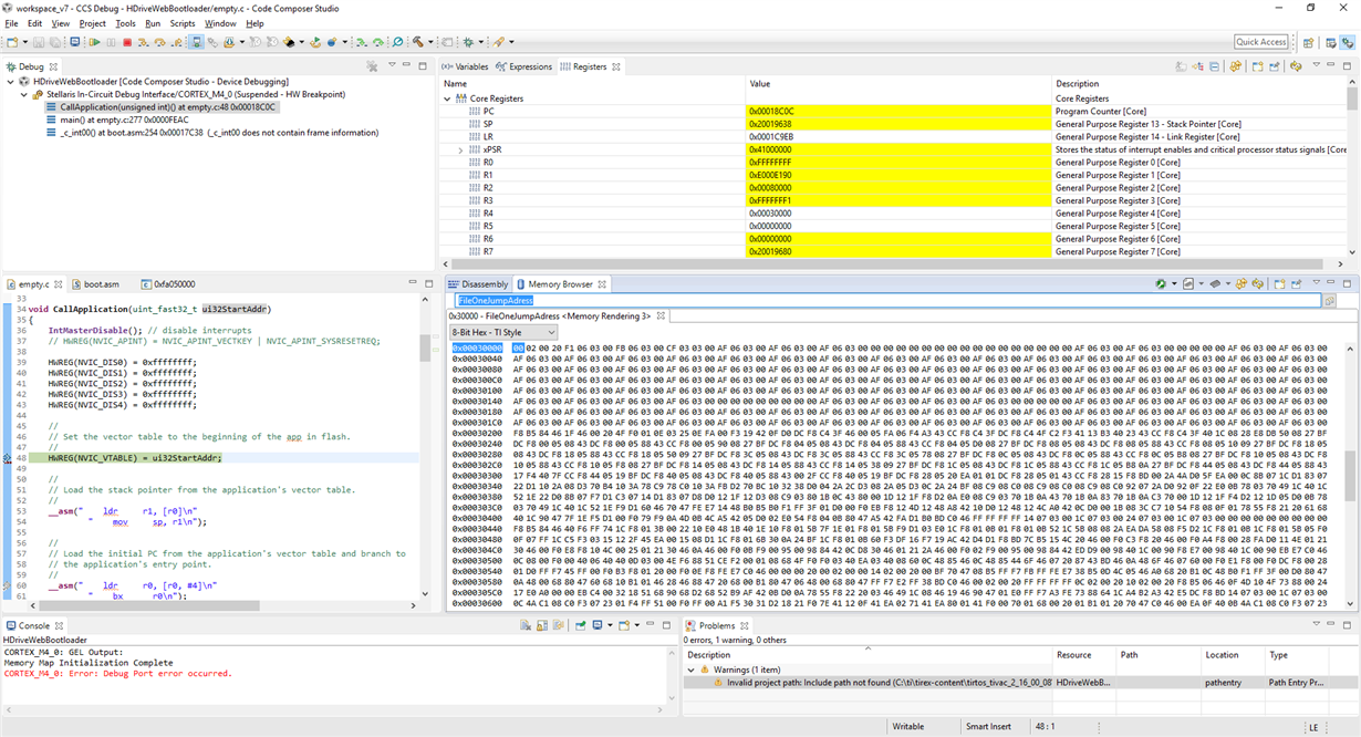
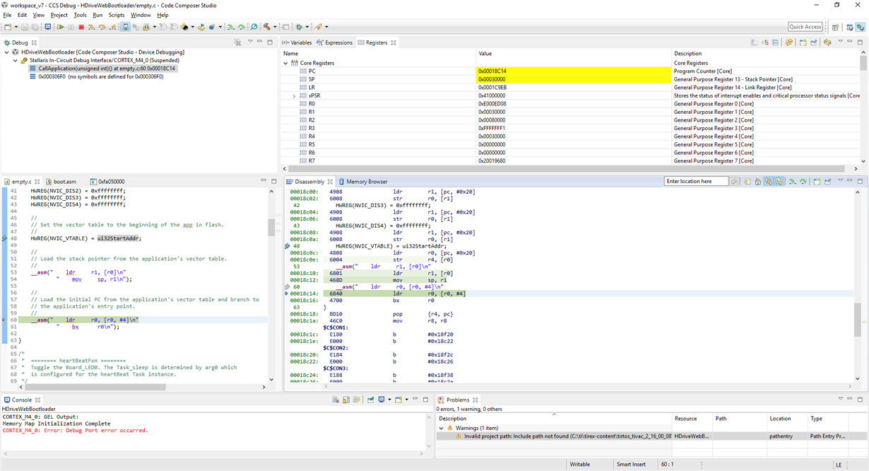
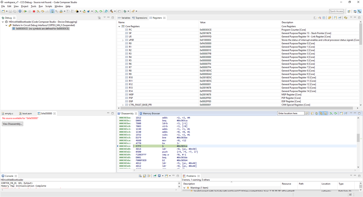
    I put some screenshots of the jumping to target application procedure:

    Before the Jump, static uint32_t FileOneAdress = 0x00030000;

    loading stack pointer:

    Branch to the wrong address? (The target application entry point should be 0x000304A8, as measured with ccs)

    Hang up at target application:

    Any idea?

  • I just figured it out.  I had put some additional code into the callApplication function, what was changing the R0 Register of the CPU.  

    I now put the application loader in the main befor I satrt BIOS, to not have problems with the TI-RTOS.

    void CallApplication(uint_fast32_t ui32StartAddr)
    {
        //
        // Set the vector table to the beginning of the app in flash.
        //
        HWREG(NVIC_VTABLE) = ui32StartAddr;
    
        //
        // Load the stack pointer from the application's vector table.
        //
        __asm("    ldr     r1, [r0]\n"
                "    mov     sp, r1\n");
    
        //
        // Load the initial PC from the application's vector table and branch to
        // the application's entry point.
        //
        __asm("    ldr     r0, [r0, #4]\n"
                "    bx      r0\n");
    }
    
    int main(void)
    {
        if (HWREG(FileOneJumpAdress) != 0xFFFFFFFF)
        {
            CallApplication(FileOneJumpAdress);
        }
    ...

    Cheers,

    Chris