This thread has been locked.

If you have a related question, please click the "Ask a related question" button in the top right corner. The newly created question will be automatically linked to this question.

TM4C1231H6PZ: TM4C1231 analog input on digital line

Part Number: TM4C1231H6PZ

Hello:

I am concerned about an analog signal input on a digital input to my TM4C1231 MCU.  

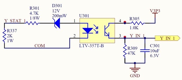
Here is my circuit:

Circuit Description:-

  1. Y_STAT_1 and COM are the 24VAC Input.
  2. Since we have Zener diode in between, circuit operates after 12V AC Peak in positive half cycle.
  3. Y_IN_1 is the digital input to TI Microcontroller P/N: TM4C1231H6PZI7
  4. Since we provide 24VAC @ 60Hz on the Y_STAT_1 and COM line, we see some ripple at the Y_IN_1.
  5. Y_IN_1 is the digital input to the controller.
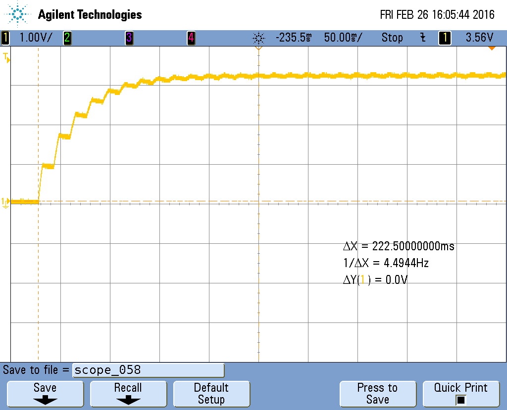
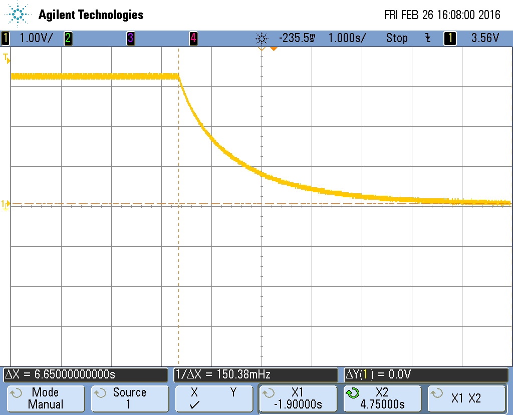
  6. Since we have C301 to get rid of some ripple of input AC cycle, when input goes off it takes some time to discharge, which is also same case when charging of the capacitor.  See Rise Time New and Fall Time New Scope shots below.
  7. Hence we can see that the microcontroller will always see as some charge and discharge time at the input of digital pin.

The question is, will it affect the controller or damage the input because of the analog nature of the signal provided over digital input line?

See the following scope shots: 

Rise time New:


Fall Time New:

We are been using the circuit in several places and concern of risk in design if exist.

Any feedback or input is welcomed and appreciated!

Thanks again!

Paul

  • Hello Paul

    As long as the input is within the device IO operating specification of supply to 0V, there is no risk of device damage. Remember that digital signal level are nothing but analog voltages constrained to logic levels.
  • Paul Schoenke said:
    Since we have C301 to get rid of some ripple of input AC cycle, when input goes off it takes some time to discharge, which is also same case when charging of the capacitor.

    The TM4C1231H6PZ datasheet says pins configured as digital inputs are Schmitt-triggered, and Table 21-6 Recommended GPIO Pad Operating Conditions shows the GPIO input hysteresis is a minimum of  0.2V.

    From the rise and fall scope captures, not sure if the during a rise or fall the schmitt-trigger GPIO input hysteresis will give a clean transition - you might need to zoom in on the scope capture to see how much "ripple" there is on the waveform to decide if some software filtering is required it a clean detection is required.

  • Chester Gillon said:
    From the rise and fall scope captures, not sure if the during a rise or fall the schmitt-trigger GPIO input hysteresis will give a clean transition -

    Not only that - the signal duration will change significantly with temperature, age, and between different PCBs. I hope you are aware of that.

    And taking a closer look at the schematics, I'm not sure about the dimensioning of C301. I would use 10nF rather than 10uF, and the long discharge (2. image) would be gone.

  • Hello Chester

    Excellent point on the hystersis. Indeed an external filter or a software filter is required.
  • f. m. said:
    And taking a closer look at the schematics, I'm not sure about the dimensioning of C301. I would use 10nF rather than 10uF, and the long discharge (2. image) would be gone.

    If C301 was changed to 10nF then the discharge time to the TM4C1231H6PZ low threshold would be approximately 190uS (VIL max) to 480us (VIH min). That would mean the TM4C1231H6PZ  would receive one pulse for every 60Hz AC cycle, meaning the software to detect the presence or absence of the AC would need to check for the presence or absence of pulses rather than checking for a high or low input.

  • Chester Gillon said:
    If C301 was changed to 10nF then the discharge time to the TM4C1231H6PZ low threshold would be approximately 190uS (VIL max) to 480us (VIH min). That would mean the TM4C1231H6PZ  would receive one pulse for every 60Hz AC cycle, meaning the software to detect the presence or absence of the AC would need to check for the presence or absence of pulses rather than checking for a high or low input.

    Actually, I'm not quite sure what the OP want to measure with his circuit, and with what precision.

    I just want to point out that:

    • larger capacities have a greater "static" effect (charge/discharge times, currents) - as the OP relized himself
    • this 10uF cap is most probably electrolytic, suffering from severe temperature and aging effects

    For precision, I would decouple filtering from the last signal forming stage.

  • Amit Ashara said:
    As long as the input is within the device IO operating specification of supply to 0V, there is no risk of device damage. Remember that digital signal level are nothing but analog voltages constrained to logic levels.

    Out of curiosity what is the input structure of the TM4C123x pins?

    There are some application reports such as Implications of Slow or Floating CMOS Inputs which show that an slow transition through the CMOS input threshold can cause an input current of several milliamps and may possibly damage the device.

    [The referenced application report is for CMOS logic devices, and not sure if it applicable to microcontrollers]

  • Hello Chester

    Unlike the MSP432 device which shows a block representation of the GPIO structure, we do not provide the same for TM4C12x devices. However for most practical purpose it is the same as the MSP432 IOs in terms of the input and output buffers & Schmitt Trigger. The Pull control is a different mechanism on the TM4C12x IOs.