This thread has been locked.

If you have a related question, please click the "Ask a related question" button in the top right corner. The newly created question will be automatically linked to this question.

TM4C123GH6PM: Problem with Timer interrupt handler

Part Number: TM4C123GH6PM
Other Parts Discussed in Thread: EK-TM4C123GXL,

I am using IAR workbench. EK-TM4C123GXL launchpad

I wrote code to get square wave 2 msec period, 50% duty cycle.

Below code works fine. My problem is with interrupt handler. How to add interrupt handler function. For my code I have added cstartup_M.c file. Is it correct way to add. If no, please share correct way.

.............................code..................................

#include <stdbool.h>
#include <stdint.h>
#include "inc/tm4c123gh6pm.h"
#include "inc/hw_ints.h"
#include "inc/hw_memmap.h"
#include "driverlib/gpio.h"
#include "driverlib/interrupt.h"
#include "driverlib/pin_map.h"
#include "driverlib/sysctl.h"
#include "driverlib/timer.h"

volatile uint8_t state=0;

uint32_t freq=0;

void TIMER0A_Handler(void)
{
TimerIntClear(TIMER0_BASE, TIMER_TIMA_TIMEOUT);
state^=GPIO_PIN_1;
GPIOPinWrite(GPIO_PORTF_BASE,GPIO_PIN_1, state);
}


int main(void)
{

SysCtlClockSet(SYSCTL_SYSDIV_5 | SYSCTL_USE_PLL | SYSCTL_OSC_MAIN | SYSCTL_XTAL_16MHZ);
SysCtlDelay(3);
freq = SysCtlClockGet();   // 40Mhz
//GPIO Configuration
SysCtlPeripheralEnable(SYSCTL_PERIPH_GPIOF);
SysCtlDelay(3);
GPIOPinTypeGPIOOutput(GPIO_PORTF_BASE, GPIO_PIN_1|GPIO_PIN_2|GPIO_PIN_3);
GPIOPinWrite(GPIO_PORTF_BASE, GPIO_PIN_1|GPIO_PIN_2|GPIO_PIN_3, 0);

SysCtlPeripheralEnable(SYSCTL_PERIPH_TIMER0);
SysCtlDelay(3);
TimerConfigure(TIMER0_BASE, TIMER_CFG_A_PERIODIC);
TimerLoadSet(TIMER0_BASE, TIMER_A, 39999);   // for 1msec
IntMasterEnable();
TimerIntEnable(TIMER0_BASE, TIMER_TIMA_TIMEOUT);
IntEnable(INT_TIMER0A);
TimerEnable(TIMER0_BASE, TIMER_A);

while(1){

}
}

.............................................................................................................................

............................ cstartup_M.c .........................................................................

/**************************************************
*
* This file contains an interrupt vector for Cortex-M written in C.
* The actual interrupt functions must be provided by the application developer.
*
* Copyright 2007 IAR Systems. All rights reserved.
*
* $Revision: 66254 $
*
**************************************************/

#pragma language=extended
#pragma segment="CSTACK"

extern void __iar_program_start( void );

extern void NMI_Handler( void );
extern void HardFault_Handler( void );
extern void MemManage_Handler( void );
extern void BusFault_Handler( void );
extern void UsageFault_Handler( void );
extern void SVC_Handler( void );
extern void DebugMon_Handler( void );
extern void PendSV_Handler( void );
extern void SysTick_Handler( void );

//...........................................................
extern void TIMER0A_Handler( void );      //************
//...........................................................
typedef void( *intfunc )( void );
typedef union { intfunc __fun; void * __ptr; } intvec_elem;

// The vector table is normally located at address 0.
// When debugging in RAM, it can be located in RAM, aligned to at least 2^6.
// If you need to define interrupt service routines,
// make a copy of this file and include it in your project.
// The name "__vector_table" has special meaning for C-SPY, which
// is where to find the SP start value.
// If vector table is not located at address 0, the user has to initialize
// the NVIC vector table register (VTOR) before using interrupts.


#pragma location = ".intvec"
const intvec_elem __vector_table[] =
{
{ .__ptr = __sfe( "CSTACK" ) },
__iar_program_start,

NMI_Handler,
HardFault_Handler,
MemManage_Handler,
BusFault_Handler,
UsageFault_Handler,
0,
0,
0,
0,
SVC_Handler,
DebugMon_Handler,
0,
PendSV_Handler,
SysTick_Handler,
//...........................................................
0,
0,
0,
0,
0,
0,
0,
0,
0,
0,
0,
0,
0,
0,
0,
0,
0,
0,
0,
TIMER0A_Handler                                      //************
//...........................................................
};

#pragma call_graph_root = "interrupt"
__weak void NMI_Handler( void ) { while (1) {} }
#pragma call_graph_root = "interrupt"
__weak void HardFault_Handler( void ) { while (1) {} }
#pragma call_graph_root = "interrupt"
__weak void MemManage_Handler( void ) { while (1) {} }
#pragma call_graph_root = "interrupt"
__weak void BusFault_Handler( void ) { while (1) {} }
#pragma call_graph_root = "interrupt"
__weak void UsageFault_Handler( void ) { while (1) {} }
#pragma call_graph_root = "interrupt"
__weak void SVC_Handler( void ) { while (1) {} }
#pragma call_graph_root = "interrupt"
__weak void DebugMon_Handler( void ) { while (1) {} }
#pragma call_graph_root = "interrupt"
__weak void PendSV_Handler( void ) { while (1) {} }
#pragma call_graph_root = "interrupt"
__weak void SysTick_Handler( void ) { while (1) {} }

//...........................................................
#pragma call_graph_root = "interrupt"
__weak void TIMER0A_Handler( void ) { while (1) {} }    //************
//...........................................................

void __cmain( void );
__weak void __iar_init_core( void );
__weak void __iar_init_vfp( void );

#pragma required=__vector_table
void __iar_program_start( void )
{
__iar_init_core();
__iar_init_vfp();
__cmain();
}

.............................................................................................................................
  • Hello Krishnat

    Yes. You need to add the Interrupt Handler at the vector location corresponding to the Interrupt Number of the timer,
  • Krishnat,
    It is ok to use timers to create a square wave - at least it is good for learning timers!
    But take a look at the PWM peripheral. If you use that, you will have your square wave working without ever again having to bother your CPU about it. It is just "initialize, start and forget about it", zero CPU consumption.
    Regards
    Bruno
  • Hi Amit, ,

    This code works fine. no error showing.

    I want to know, Is it correct way of config, ADC in always mode.

    One more question, If I use previous Timer and this ADC , will it work fine..If I am missing any please tell

     thanx & regards 

    Krishnat

    ................................  ADC Code...............................................................

    SysCtlClockSet(SYSCTL_SYSDIV_5 | SYSCTL_USE_PLL | SYSCTL_OSC_MAIN | SYSCTL_XTAL_16MHZ);
    SysCtlDelay(3);
    freq = SysCtlClockGet();


    //GPIO Configuration
    SysCtlPeripheralEnable(SYSCTL_PERIPH_GPIOF);
    SysCtlDelay(3);
    GPIOPinTypeGPIOOutput(GPIO_PORTF_BASE, GPIO_PIN_1|GPIO_PIN_2|GPIO_PIN_3);
    GPIOPinWrite(GPIO_PORTF_BASE, GPIO_PIN_1|GPIO_PIN_2|GPIO_PIN_3, 0);


    //ADC Configuration
    SysCtlPeripheralEnable(SYSCTL_PERIPH_ADC0);
    SysCtlDelay(3);
    SysCtlPeripheralEnable(SYSCTL_PERIPH_GPIOE);
    SysCtlDelay(3);
    GPIOPinTypeADC(GPIO_PORTE_BASE, GPIO_PIN_2);
    ADCSequenceConfigure(ADC0_BASE, 3, ADC_TRIGGER_ALWAYS, 0);
    ADCSequenceStepConfigure(ADC0_BASE, 3, 0, ADC_CTL_CH1 | ADC_CTL_IE | ADC_CTL_END);
    ADCSequenceEnable(ADC0_BASE, 3);
    ADCIntClear(ADC0_BASE, 3);


    while(1)
    {
      while(!ADCIntStatus(ADC0_BASE, 3, false)) {

      }
      ADCIntClear(ADC0_BASE, 3);
      ADCSequenceDataGet(ADC0_BASE, 3, &a[i]);
    }

  • HI,

    I hope you will send me correction in above ADC code.
    I more thing I want is, DRM style code of particular part of code

    ......... Want DRM style code of belo part......................................

    while(!ADCIntStatus(ADC0_BASE, 3, false)) {

    }
    ADCIntClear(ADC0_BASE, 3);
    ADCSequenceDataGet(ADC0_BASE, 3, &a[i]);
    .......................................................................................................

    This is because,
    ADCSequenceDataGet(ADC0_BASE, 3, &a[i]); // Takes 1047 nano sec to execute
    a[i] = ADC0->SSFIFO3 & 0XFFF; // Takes 477 nano sec to execute

    difference of 570 nano sec makes big impact on my code.
    I have pulse below 100 u sec width to scan.
    If one line of code make difference 570 ns.
    then while(!ADCIntStatus... will make more difference..
    so I want to make DRM style code for this part of code.

    Regards,

    Krishnat

  • Hello Krishnat

    When operating the ADC controller for maximum sampling rate, the CPU may have an overhead moving the data. Did you check if DMA can be used instead? If DMA cannot be used for your application, it would require either DRM. Also you can evaluate the ROM version of the API as it would be a single cycle path.
  • Hi ,

    Other part of code will execute once, there no problem with using API.

    I just want to know which registers being addressed in below 2 line code so I can write DRM style code for that 2 line of code.

    while(!ADCIntStatus(ADC0_BASE, 3, false)) {};    ---> Don't know
    ADCIntClear(ADC0_BASE, 3);                                 ---> Don't know
    ADCSequenceDataGet(ADC0_BASE, 3, &a[i]);    ---> a[i] = ADC0->SSFIFO3 & 0XFFF;  <--- for this line I know

    Regards,

    Krishnat

  • Hello Krishnat,

    First the good part:

    HOW TO VIEW THE SOURCE CODE FOR THE TIVAWARE API'S

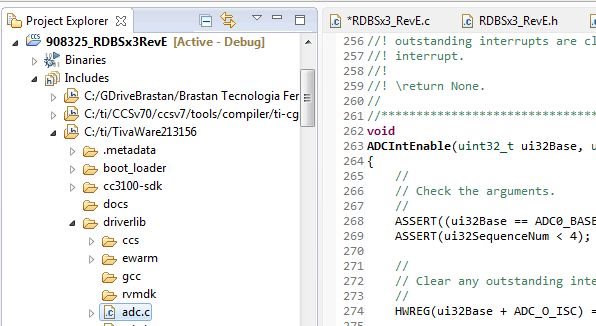
    It is very easy for you to find what happens inside any TivaWare function! Just "follow the code":

    - Click on the function while holding control, and CCS will probably open the header file where such function is declared.
    - Let's say you want to view ADCIntEnable() - click on it and see that it is declared as an extern on adc.h.
    - Well, there is a .c file with the same name, that can be found on the included folders of your project. Open that file (adc.c)
    - Find the function inside such file, and the full code is right there for you!

    Now, the "bad part":

    Most most most of the times, you will gain NOTHING by changing your application code from TivaWare into DRM.

    - Tivaware has a copy of the API on the ROM of your MCU. It takes LESS FLASH MEMORY and it is FASTER
    - You don't have to repeat code a gazzillion times
    - If you port your program to another TM4C MCU, you won't even have to bother what are the new register addresses

    Are these convincing enough?

    Cheers

    Bruno

  • hi,

    I dont find correct code for adc in always mode.

    I want adc with interrupt handler.

    Regards

    Krishnat

  • Hello Krishnat,

    The Interrupt handler will take more CPU cycles to load and execute the same code that you are doing outside of the interrupt handler. Considering that it is ADC in always trigger mode, that would bog down the CPU execution. I would strongly suggest using DMA instead.
  • This thread is called "Problem with Timer interrupt handler"

    If we continue replying here, it will be a private consulting, and nobody will ever use this in the future to seek answers for specific questions. I'd like to ask the poster, if he has new questions, to search for previous posts in the forum, or to create a new thread with a specific title - making it useful for others later.
  • HI amit,

    I think I earlier talk with u about DMA. I will definitely do ADC DMA code.
    Prior to that I wanted to do ADC in always trigger mode with interrupt handler and/or polling method.
    I got some clues from datasheet, i will do it tomorrow n come with solution.

    Regards,
    Krishnat.
  • HI bruno,
    I dont think this will lead to private consulting.
    Because..
    First I asked about interrupt handler of timer
    Secondly I am asking about adc in always mode with interrupt
    finally when I combine both module there is "HARDFAULT ERROR"..which I think related to again interrupt handler and related to interrupt priority.

    these all connected.

    When I m done, I will post working codes here, so newbie like me will get definite help.

    Regards,
    Krishnat
  • Krishnat,

    It is already difficult to find answers on the forum, given the multitude of search terms, and the complexity of the subject.

    Imagine that some months into the future, someone has a problem regarding "asking about adc in always mode with interrupt". And let's say that someone gives you a PERFECT answer right here on THIS thread today.

    Do you think that anyone will open a thread called "Problem with Timer interrupt handler" and hope to find his problem solved?

    Anyway, that's just how my "logical brain" likes to function. A new post is "free", and will likely makes things easier: its content, as much as possible, should be related to the title. Particularly, when the solution for the first problem is given, OP shall mark it as solved and move on - to the next post!!!

    Cheers
  • HI
    in that case.. I will simply paste my working code in other post named adc in always mode with interrupt.. there are lot of similar post on forum with no particular answer.
    you are right too. but in every step newbie like me gets problem and making new post for same feeling annoying.

    Regards,
    krishnat