Other Parts Discussed in Thread: TM4C123GH6PM,
Tool/software: Code Composer Studio
Hello All,
I have been trying to get the SSI ports of the TM4C123GH6PM (Stellaris Launchpad) configured, but there are three problems I have been facing now. The details are as below:
I have two E-Paper displays (http://cdn-reichelt.de/documents/datenblatt/A400/EA_EPA20-A.pdf) (Controller:http://www.lcd-module.de/eng/pdf/zubehoer/ssd1606_1_1.pdf) connected to the 2nd and the 3rd SSI ports of the uC. The connections are one to one with no series or pull-up/down resistors etc. But there is something very strange, that is happening and I can't seem to use both the SSI ports at the same time.
Connection Details:
LCD 1:
PB7 -> MOSI(2) -> LCD1_MOSI
PB5 -> CS(2) -> LCD1_CS
PB4 -> SCK(2) -> LCD1_SCK
LCD 2:
PD3 -> MOSI(3) -> LCD2_MOSI
PD1 -> CS(3) -> LCD2_CS
PD0 -> SCK(3) -> LCD2_SCK
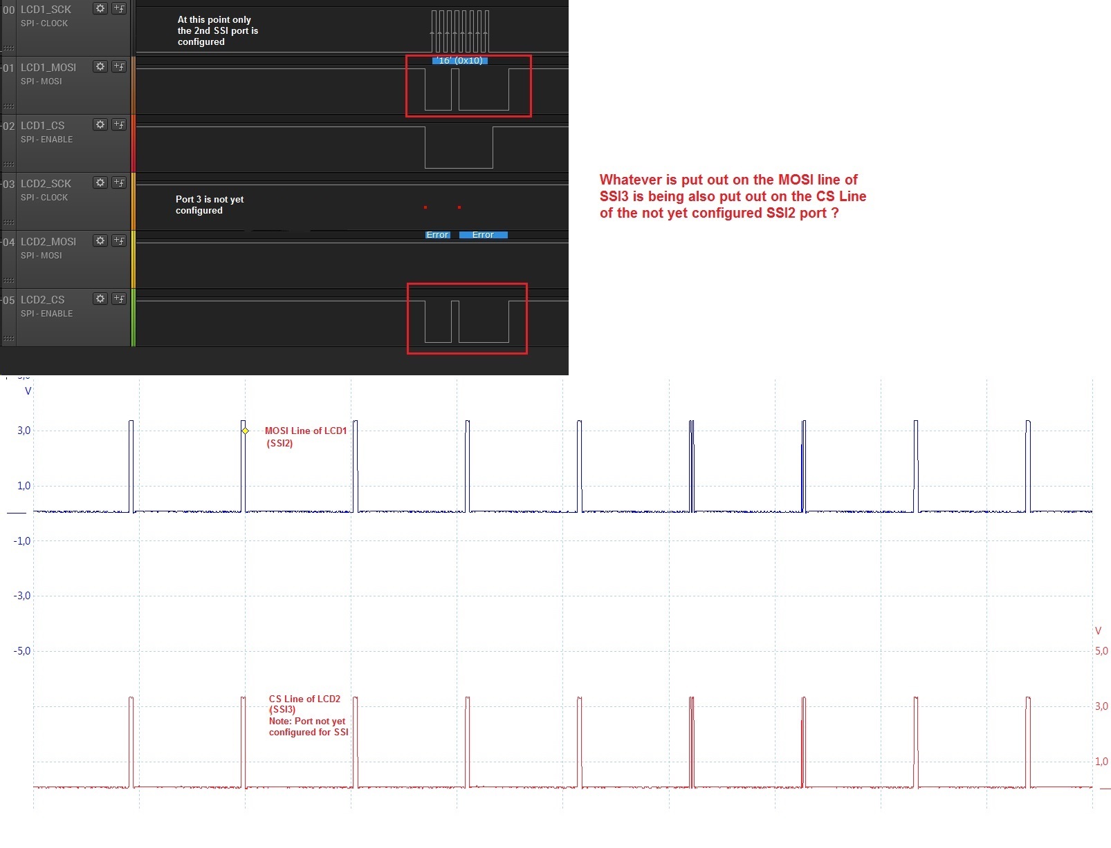
Test 1: SSI2 is configured and enabled (SSI3 is not yet configured). Then send the data to the first LCD and it works without any issues. However, I see the CS line of SSI3 switching, when the MOSI line of the SSI2 switches ? Any idea, why this is happening ? (See Screenshot_One below)
Screenshot_One:
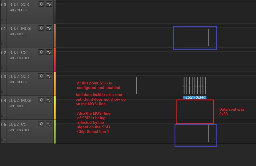
Test 2: Now I configure the SSI3 port and enable it (SSI2 is configured and enabled already). I also send out data 0x80 out on SSI3, but it does not appear on the MOSI line although I see the clock pulses. Again, what am I doing wrong ? Also the when the CS line of SSI3 switches, the MOSI line of the SSI2 port also switches ? (See Screenshot_two below)
Screenshot_Two:
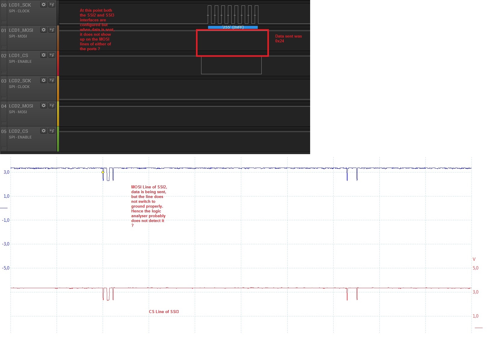
Test 3: Now both SSI3 and SSI2 are configured and enabled. I now again try to send data (0x24) on the SSI2 port, but again I see the clock pulses, but nothing on the MOSI on the logic analyser. After looking at the signals on the scope, it seems that the data is being transmitted but the line is not switching properly. Why is this happening now after both the SSI ports were enabled and not when only one port was enabled ?
Initially, I tried with the displays connected to the launchpad, but then even tried this with only the launchpad without any components connected to it, the results was the same.
(See Screenshot_Three below)
Screenshot_Three:
Some help/pointers would be nice. I am not exactly sure, why this is happening ? I am using the following code (No interrupts, only polling, CCS compiler: 5.1.14, Tivaware: 2.1.3.156)
-
Inder.
//Code Snippet for the enabling and configuring SSI2 and 3

void LCD1_SPI_Init(void)
{
	//SSI2 Configuration
	SysCtlPeripheralEnable(SYSCTL_PERIPH_GPIOB);
	GPIOPinConfigure(GPIO_PB4_SSI2CLK);
	GPIOPinConfigure(GPIO_PB5_SSI2FSS);
	GPIOPinConfigure(GPIO_PB7_SSI2TX);

	GPIOPinTypeSSI(GPIO_PORTB_BASE, GPIO_PIN_4 | GPIO_PIN_5 | GPIO_PIN_7);

	SysCtlPeripheralEnable(SYSCTL_PERIPH_SSI2);

	SSIIntDisable(SSI2_BASE, SSI_TXFF | SSI_RXFF | SSI_RXTO | SSI_RXOR);
	SSIConfigSetExpClk(SSI2_BASE, 80000000, SSI_FRF_MOTO_MODE_0, SSI_MODE_MASTER, 2000000, 8);

	SSIEnable(SSI2_BASE);
}

void LCD2_SPI_Init(void)
{
	//SSI3 Configuration
	SysCtlPeripheralEnable(SYSCTL_PERIPH_GPIOD);
	GPIOPinConfigure(GPIO_PD0_SSI3CLK);
	GPIOPinConfigure(GPIO_PD1_SSI3FSS);
	GPIOPinConfigure(GPIO_PD3_SSI3TX);

	GPIOPinTypeSSI(GPIO_PORTD_BASE, GPIO_PIN_0 | GPIO_PIN_1 | GPIO_PIN_3);

	SysCtlPeripheralEnable(SYSCTL_PERIPH_SSI3);

	SSIIntDisable(SSI3_BASE, SSI_TXFF | SSI_RXFF | SSI_RXTO | SSI_RXOR);
	SSIConfigSetExpClk(SSI3_BASE, 80000000, SSI_FRF_MOTO_MODE_0, SSI_MODE_MASTER, 2000000, 8);

	SSIEnable(SSI3_BASE);
}

//Delay

void delay(unsigned long usecs){ //delay in 100us units
  unsigned long count;
  while(usecs > 0 )
  {
    count = 666; //Set this to 6666 for 1ms (for 80Mhz clk)
    while (count > 0)
    {
      count--;
    } // This while loop takes approximately 3 cycles
    usecs--;
  }
}


//Code for sending commands and data to the displays

void writecmd_LCD1(char data)
{
	//GPIOPinWrite(GPIO_PORTE_BASE, GPIO_PIN_1, 0); //Pull to Low since this is a command
	SSIDataPut(SSI2_BASE, data);
	while(SSIBusy(SSI2_BASE));
	delay(1);
}

void writedata_LCD1(char data)
{
	//GPIOPinWrite(GPIO_PORTE_BASE, GPIO_PIN_1, GPIO_PIN_1); //Pull to high since this is data
	SSIDataPut(SSI2_BASE, data);
	while(SSIBusy(SSI2_BASE));
	delay(1);
}

void writecmd_LCD2(char data)
{
	//GPIOPinWrite(GPIO_PORTE_BASE, GPIO_PIN_5, 0); //Pull to Low since this is a command
	SSIDataPut(SSI3_BASE, data);
	while(SSIBusy(SSI3_BASE));
	delay(1);
}

void writedata_LCD2(char data)
{
	//GPIOPinWrite(GPIO_PORTE_BASE, GPIO_PIN_5, GPIO_PIN_5); //Pull to high since this is data
	SSIDataPut(SSI3_BASE, data);
	while(SSIBusy(SSI3_BASE));
	delay(1);
}

//Main Section

int main(void) {

	uint32_t temp;

	SysCtlClockSet(SYSCTL_SYSDIV_2_5 | SYSCTL_USE_PLL | SYSCTL_XTAL_16MHZ | SYSCTL_OSC_MAIN);

	LCD1_SPI_Init();

        writecmd_LCD1(0x10);
        delay(20000);

        LCD2_SPI_Init();
        delay(20000);

	while(1)
	{

        writecmd_LCD2(0x80);
        delay(20000);

        writecmd_LCD1(0x24);
        delay(20000);
	}

	return 0;
}


