This thread has been locked.

If you have a related question, please click the "Ask a related question" button in the top right corner. The newly created question will be automatically linked to this question.

Can we unlock TM4C129x flash by API

Other Parts Discussed in Thread: UNIFLASH

Hi

We want to protect 16 KB bootloader code as read only by call FlashProtectSet(ui32Address, FlashReadOnly). It's customized bootloader saved in Flash.

But it make sure it can be updated by external MCU instead of unlock by LM Flash programmer or Uniflash with ICDI. So can we unlock it by API function in application code in condition of receiver some specific command from external controller? 

It seems there is a small amount of time during reset where the flash will not be protected until the HW load the values that have been committed for the Flash Memory Protection Registers.

Can we make use of this momentary time to unlock it by API and erase flash? If yes, could you share us some code example how to do that? Thanks a lot.


  • Hi Daniel,
    Once committed, a locked block is permanently locked and this is non-reversible by power cycle. There is no API to unlock. If there is one then it would have defeated the purpose of protecting it in the first place.
  • Thanks Charles,

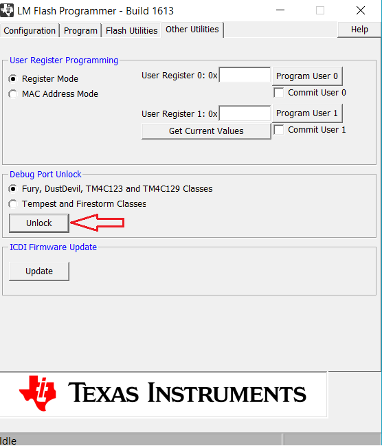
    If it's  is permanently locked.  why it can be unlock by LM flash programmer?

  • Hi Daniel,

    The debug port unlock will unlock the JTAG debug pins by performing a mass erase of the internal flash. Your device become fresh again. Your bootloader will be erased in the process.
  • Hi Charles,

    Can we use external MCU control debug port to do a mass erase firstly? then write a complete new firmware to flash including new protected bootloader.

  • Hi Daniel,

     Please refer to Recovering a "Lock" Microcontroller section in the JTAG chapter in the datasheet on the sequence to unlock if you are developing a custom JTAG programmer using an external MCU. I copy the excerpt from the datasheet.

    1. Assert and hold the RST signal.
    2. Apply power to the device.

    3. Perform steps 1 and 2 of the JTAG-to-SWD switch sequence on the section called “JTAG-to-SWD
    Switching” on page 214.
    4. Perform steps 1 and 2 of the SWD-to-JTAG switch sequence on the section called “SWD-to-JTAG
    Switching” on page 215.
    5. Perform steps 1 and 2 of the JTAG-to-SWD switch sequence.
    6. Perform steps 1 and 2 of the SWD-to-JTAG switch sequence.
    7. Perform steps 1 and 2 of the JTAG-to-SWD switch sequence.
    8. Perform steps 1 and 2 of the SWD-to-JTAG switch sequence.
    9. Perform steps 1 and 2 of the JTAG-to-SWD switch sequence.
    10. Perform steps 1 and 2 of the SWD-to-JTAG switch sequence.
    11. Perform steps 1 and 2 of the JTAG-to-SWD switch sequence.
    12. Perform steps 1 and 2 of the SWD-to-JTAG switch sequence.
    13. Release the RST signal.
    14. Wait 400 ms.
    15. Power-cycle the microcontroller.

  • It's great, Thanks.