This thread has been locked.

If you have a related question, please click the "Ask a related question" button in the top right corner. The newly created question will be automatically linked to this question.

TM4C123GH6PM: CPU gets hot - PCB layout issue

Part Number: TM4C123GH6PM

I have a board with 4 small dc motors connected to H-Bridges and 1 hobby-style servo connected. I was running a script for a few hours to stress test the board. I heard my PC complaining about the USB dropping out, so I checked on it and the CPU was hot to the touch. After turning off the equipment and coming back later, the CPU does heat up quickly once power is applied.

The board draws between 7 and 10mA more than it did previously during idle, however everything appears to function correctly - albiet at a high temperature. I believe this indicates transistor level damage to the chip itself, however I do not know where I need to add protection or rework the board.

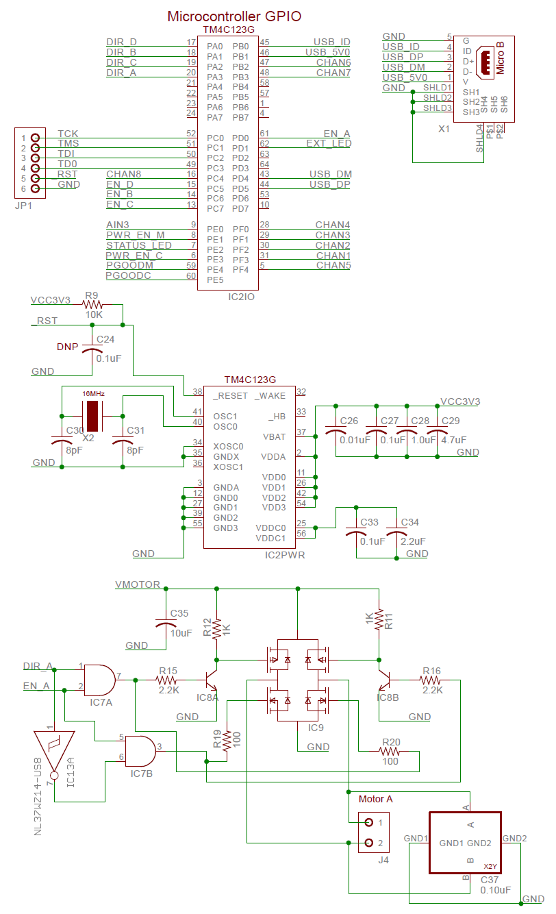
Also, I was wondering if it might be due to my neglecting the addition of resistors between GPIO pins and the h-bridge components. However, it is my understanding that there are current limiting components in the GPIO peripheral pins which would make this concern a non-issue.

Please help out with advice - this board is for a robotics platform used for getting kids interested in writing software and developing hardware.

  • Mark Taylor said:
    it is my understanding that there are current limiting components in the GPIO peripheral pins

    "Ouch" (said the MCU) which includes "voltage-limiting/ESD diodes" (internally) upon GPIO pins - which are NOT known for limiting current!

    Safest & best "noise limiting" would result from your use of separate power supplies for "V_Motor" and the derivation of 3V3 for the MCU.   In addition - a small (external) R-C filter would aid those GPIO pins tasked w/motor drive connection.   (the R in that case may serve as (both) input filter & (your earlier sought) GPIO current limiting...   It is possible (even likely) that V_Motor noise/spikes are coupling into your PC (via the USB cable) which caused your "PC to (rightly) complain."     Clearly you do NOT want to destroy the "kidz" PCs - such "interest" is to be avoided!

    While unlikely to have caused damage - it would prove wise to "place" your C24 (reset filter) cap.    Proper & robust MCU Power & Reset circuits are mandatory...

    Note that there are Brushed Motor Drive ICs which would substantially reduce your BOM - making board size & assembly far faster/easier...

  • cb1,

    Thank you for jumping in with your good suggestions. I am really impressed how helpful some of you experienced users are to other members of this forum.


    Mark,

    One thing I might add is that you should take some care of pin PB1 as it is not truly 5V tolerant. (I know that even some TI designs have ignored this requirement so it is often overlooked.) See section 4.1 of the Layout Guidelines for suggestions.

  • Thank you as well Bob - note that we are (equally) impressed w/your: skill, caring, & presentation of clear detail...
  • When I said that I believed the GPIO pins have current limiting components, I was referring to the programmable drive strength for GPIO pins.

    For example, in drivers/gpio/GPIOTiva.h, there are three options relating to 2, 4 and 8mA drive strengths:
    GPIO_CFG_OUT_STR_LOW
    GPIO_CFG_OUT_STR_MED
    GPIO_CFG_OUT_STR_HIGH

    Mine are all set for 8mA...

    V_Motor and VCC3V3 are not directly shared. There is a Vin pin which is tolerant to 16V. From there, V_MOTOR is regulated by a switching supply to 5V. VCC3V3 is based on an LDO.

    If noise was coupling to the USB lines, it would complain immediately. It only did that after several hours when the CPU had started getting hot - indicating that the CPU was beginning to fail.

    This is Rev B of the board. An O-Scope showed that the original version did have a problem with motors injecting noise across the board and browning out the CPU during surges. This version is filtered much better. Digital and motor power busses are isolated through ferrite beads. The motor components are additionally filtered with X2Y caps. Transient noise is likely not the cause of this.

    I have used motor driver ICs for steppers before and they are helpful. They are usually more expensive, but seeing as though I'm hand assembling these prototype boards and baking them myself, I may look into getting ICs - thanks for the suggestion.
  • This is very interesting indeed! So, let's say I have a JTAG on my processor and everything is hooked up and powered - ready to go... According to the doc you cited, I'm actually frying my CPU while the processor is sitting there waiting for me to push the run button in the debugger (i.e., CPU halted in reset - no USB stack running yet). Would you suggest I find an alternate pin to use and modify the SW that TI provides in their TI-RTOS USB examples to use this alternate pin?

    "When configured as USB0VBUS,
    this pin is 5-V tolerant. However, when used as a GPIO input, PB1 is NOT 5-V tolerant. An alternate 5-V
    tolerant Fail-Safe GPIO should be selected to do the VBUS detection if there is a chance 5V could be
    applied to the input prior to PB1 on the TM4C123x device being configured for VBUS, such as during
    power-up, while the device is in reset, and the while the initial boot sequence executes."
  • If you need true OTG mode, yes. If you need Device only mode, a simple 100 Ohm resistor will suffice.
  • You're saying I don't need to choose an alternate pin for USB0VBUS?

    I think that doc says that I MUST choose another pin, simply due to the fact that the device is always plugged in via USB and will transition from reset to running states periodically (JTAG debugging, booting, etc.):
    "An alternate 5-V
    tolerant Fail-Safe GPIO should be selected to do the VBUS detection if there is a chance 5V could be
    applied to the input prior to PB1 on the TM4C123x device being configured for VBUS, such as during
    power-up, while the device is in reset, and the while the initial boot sequence executes."

    However, regardless of it this were true, it does say that I need a series resistor to limit ESD damage:
    "For a USB device-only configuration, a 100Ω resistor should be placed in series between VBUS on the
    USB connector and PB1 (or alternate 5-V tolerant GPIO) on the microcontroller in order to limit damage
    caused by any ESD events."
  • Mark Taylor said:
    I was referring to the programmable drive strength for GPIO pins.

    Having past worked at a similar semi-giant it is my belief that the "programmable drive strength" you note does NOT extend into full/total protection of the entire pin circuit.    (i.e. it is "output current sink/source based" most likely)      More expansive GPIO pin network protection is afforded by the presence of a properly chosen & placed, external, series connected, GPIO resistor(s).

    I don't believe that you've "made the case" yet for your PC "complaining immediately" NOT resulting from (likely) motor/over-challenged power delivery/distribution.    You don't really know when your CPU started getting hot - isn't that true?

    Your report of the CPU "browning out" during surges suggests that your power supply/distribution system may be inadequate.    Minus robust power provisioning & delivery you place the MCU & other critical components (always) at risk...

  • No, I don't know when it started getting hot. It probably had two days of continuous unattended run time on it when it started. The power situation is clean now, but I agree that placing some resistors on GPIOs is always a good idea. However, I am hesitant to think that I can't rely on the reported programmable drive strength reported in the manual for driving some logic gates.
  • cb1 is absolutely correct. The drive strength refers to the programmable output buffers and means that the output buffer can drive or sink a minimum of x(2, 4 or 8)mA and still achieve a valid logic level of high or low. In fact, the output buffer can drive much more than that, particularly if the resistance of the load is too low for the buffer to achieve its output level. For example if you configure a GPIO as a 2mA output and try to set it high, but it is tied on the board to ground, it will drive much more than 2mA and it will get hot. If you configure it as an 8mA output, it will drive more current and get even hotter. That being said, I doubt that driving a shorted output pin is your problem.

    That brings me to the next point cb1 is making. These small CMOS transistors are inherently susceptible to damage by high voltages. High voltages can come from static discharges or fly-back from switching inductive loads among other things. We put ESD protection circuits on the device pins to protect them. These ESD circuits turn on and redirect the energy back into the chip ground. The protection must turn on very quickly to prevent damage so they turn on as a function of not just the absolute voltage, but of the change in voltage over time (dv/dt). When they turn on they necessarily have a very low impedance path to ground. Unfortunately, when the ESD circuits turn on and have too much current, they can turn on a parasitic SCR. Once this unintentional SCR turns on, it will not turn off until the current source is removed. Either the voltage is removed from the pin externally, or it is removed when the bond-wire or internal copper traces melt. This is called "latchup".

    There is one more twist to the story, and this may be the root cause and the story behind PB1. When you attach a low impedance supply pin like USB_5V0 to a pin, you can get a very fast rise time. If it is fast enough, and goes above VDD (3.3V), it may turn on the ESD protection. As soon as the ESD protection turns on, it pulls down the current limited USB_5V0. That turns off the ESD circuit. USB_5V0 rises again quickly, and the ESD circuit turns on again. The cycle repeats ... Things get hot, but may not melt. However it is certainly not what we want. We only need to limit the current a little bit to prevent this ESD turn on oscillation from happening. That is what the 100 Ohm resistor does.

    My disclaimer: I do not know that this is the reason behind PB1 not being labeled as "5V tolerant". I was not part of this team at the time of the chip development and verification. (Maybe Amit will see this and chime in.) However, I was involved with another family on the same process node and became more intimately familiar with the ESD structures than I ever wanted to be. This explanation would explain why the pin can be connected to USB_5V0 through the 100 Ohm resistor in device mode. Unfortunately the voltage drop caused by the resistor when the micro must drive USB_5V0 in OTG mode precludes its use.
  • You and cb1 have given me a lot of information to think about! So I definitely need a resistor on the USB_5V0 pin - check. If the gates of those logic chips (AND/OR) gates driving the H-bridge can draw more than 8mA, I definitely need resistors there too, because the CPU will happily kill itself supplying more. Is this all correct?
  • Thanks (again) to vendor's Bob for his kind support.

    Having worked long/hard in BLDC Motor Drive - I note that the (extent) of your multi-chip drive solution provides substantial pcb area (likely excessive area) which serves to "invite" (unwanted) noise and inductive kickback (i.e. likely serves as an antenna) - and feedback some of that to the (delicate) GPIO pin structure. (as both Bob & I noted - that portion of the GPIO NOT protected by the output drive circuitry) Killing just one portion of the complex GPIO pin structure is likely to impact the entirety of that structure - especially as the effect cascades w/use & time. (somewhere I have photo-micrographs which show this effect growing & propagating...)

    The cost/size penalty imposed by 06-03 smt, GPIO resistors pales in comparison to the cost, time & delays which "lesser protected" GPIO circuits enable...    Note too that you've tested your circuit (most likely) with small, brushed motors.    I can guarantee that the "kidz" will one day arrive w/a more "power-hungry" motor - thus the caution to insure that your power supplies are robust, proper and that all "basic" MCU protections are in place.